EP1445832A2 - Combination d'antennes pour multiples radio services pour vehicules - Google Patents
Combination d'antennes pour multiples radio services pour vehicules Download PDFInfo
- Publication number
- EP1445832A2 EP1445832A2 EP04002306A EP04002306A EP1445832A2 EP 1445832 A2 EP1445832 A2 EP 1445832A2 EP 04002306 A EP04002306 A EP 04002306A EP 04002306 A EP04002306 A EP 04002306A EP 1445832 A2 EP1445832 A2 EP 1445832A2
- Authority
- EP
- European Patent Office
- Prior art keywords
- radio service
- frequency range
- frequency
- antenna
- reactance
- Prior art date
- Legal status (The legal status is an assumption and is not a legal conclusion. Google has not performed a legal analysis and makes no representation as to the accuracy of the status listed.)
- Withdrawn
Links
Images


Classifications
-
- H—ELECTRICITY
- H01—ELECTRIC ELEMENTS
- H01Q—ANTENNAS, i.e. RADIO AERIALS
- H01Q1/00—Details of, or arrangements associated with, antennas
- H01Q1/27—Adaptation for use in or on movable bodies
- H01Q1/32—Adaptation for use in or on road or rail vehicles
-
- H—ELECTRICITY
- H01—ELECTRIC ELEMENTS
- H01Q—ANTENNAS, i.e. RADIO AERIALS
- H01Q21/00—Antenna arrays or systems
- H01Q21/29—Combinations of different interacting antenna units for giving a desired directional characteristic
-
- H—ELECTRICITY
- H01—ELECTRIC ELEMENTS
- H01Q—ANTENNAS, i.e. RADIO AERIALS
- H01Q1/00—Details of, or arrangements associated with, antennas
- H01Q1/52—Means for reducing coupling between antennas; Means for reducing coupling between an antenna and another structure
- H01Q1/521—Means for reducing coupling between antennas; Means for reducing coupling between an antenna and another structure reducing the coupling between adjacent antennas
-
- H—ELECTRICITY
- H01—ELECTRIC ELEMENTS
- H01Q—ANTENNAS, i.e. RADIO AERIALS
- H01Q21/00—Antenna arrays or systems
- H01Q21/28—Combinations of substantially independent non-interacting antenna units or systems
-
- H—ELECTRICITY
- H01—ELECTRIC ELEMENTS
- H01Q—ANTENNAS, i.e. RADIO AERIALS
- H01Q5/00—Arrangements for simultaneous operation of antennas on two or more different wavebands, e.g. dual-band or multi-band arrangements
- H01Q5/20—Arrangements for simultaneous operation of antennas on two or more different wavebands, e.g. dual-band or multi-band arrangements characterised by the operating wavebands
- H01Q5/28—Arrangements for establishing polarisation or beam width over two or more different wavebands
-
- H—ELECTRICITY
- H01—ELECTRIC ELEMENTS
- H01Q—ANTENNAS, i.e. RADIO AERIALS
- H01Q5/00—Arrangements for simultaneous operation of antennas on two or more different wavebands, e.g. dual-band or multi-band arrangements
- H01Q5/30—Arrangements for providing operation on different wavebands
- H01Q5/307—Individual or coupled radiating elements, each element being fed in an unspecified way
- H01Q5/314—Individual or coupled radiating elements, each element being fed in an unspecified way using frequency dependent circuits or components, e.g. trap circuits or capacitors
- H01Q5/321—Individual or coupled radiating elements, each element being fed in an unspecified way using frequency dependent circuits or components, e.g. trap circuits or capacitors within a radiating element or between connected radiating elements
-
- H—ELECTRICITY
- H01—ELECTRIC ELEMENTS
- H01Q—ANTENNAS, i.e. RADIO AERIALS
- H01Q9/00—Electrically-short antennas having dimensions not more than twice the operating wavelength and consisting of conductive active radiating elements
- H01Q9/04—Resonant antennas
- H01Q9/30—Resonant antennas with feed to end of elongated active element, e.g. unipole
- H01Q9/32—Vertical arrangement of element
- H01Q9/36—Vertical arrangement of element with top loading
Definitions
- the invention relates to a combination antenna arrangement for at least two radio services for vehicles, of which for the first radio service in one assigned to it Frequency range at a designated antenna connection point a narrowly tolerated Directional diagram is designed.
- the EP 0 837 521 B1 describes a combined antenna form, for which as an application example the telephone services of the GSM-900 and the GSM-1800 system (mobile radio systems of the D network and E network) as well as the AMPS system used in the USA.
- a satellite radio service should be made possible for these telephone services, e.g. the global Positioning System (GPS) or a planned bidirectional satellite radio service with low-flying satellites (Leos).
- GPS global Positioning System
- Leos planned bidirectional satellite radio service with low-flying satellites
- the combination of satellite antennas is particularly for satellite radio services as the first radio service 1 and antennas for other radio services 2 in a narrow space due to the radiation coupling between the antennas and the associated deformation of the directional diagram problem with the satellite antenna. This is particularly due to the tight dimension Link budget justifies what happens if the directional diagram is deformed drastically can lead to the disconnection of the radio connection.
- the standard of satellite broadcasting SDARS in the elevation angle range e.g. between 25 or 30 degrees and 60 or 90 degrees an antenna gain depending on the operator of constant e.g. 2 dBi or e.g. 3 dBi strictly required for circular polarization.
- This requirement exists for an antenna built on the center of a flat conductive base plate. This The requirement is only to be met if the deviation from the ideal radiation characteristic is not more than approx. 0.5 dB in any solid angle.
- the directional diagram is particularly in view of that on vehicles for antennas known scale tolerated extremely closely.
- DE 101 08 910 e.g. the design of one Antenna specified, which enables compliance with the narrowly tolerated directional diagram.
- antennas of this design the antenna gain required in the area of the zenith angle can be achieved generally realize problem-free.
- this antenna there is reception terrestrially broadcast signals according to the SDARS standard with a monopole antenna combined, resulting in a small design which is advantageous for use on vehicles of the combined antenna for the first radio service 1.
- a tight tolerance requirement is to be largely maintained accordingly for installation on a vehicle.
- the object of the present invention is therefore to provide measures for the design of Near field of a first antenna for a first radio service with a narrowly tolerated antenna pattern attached or combined with this antenna for other radio services, which the disadvantages of the deformation of the antenna pattern of the antenna for avoid the first radio service.
- the great advantage of antenna arrangements according to the invention is that Focus combination antennas for multiple radio services for vehicles in extremely small spaces to be able to do this without having to make particularly tough demands for the first radio service diagram deformations inadmissible with regard to adherence to a target directional diagram To have to buy.
- an antenna arrangement according to the invention in a housing with the dimensions of about 12 by 5 cm (corresponding to only about 1 ⁇ by 0.4 ⁇ ) on the wavelength of the SDARS service) a high-precision antenna for SDARS (first Radio service 1) with 2 combination antennas for AMPS and PCS radio telephone (further radio services 2) to combine, the antennas for these other radio services only one Distance of about 0.3 ⁇ , based on the wavelength of the SDARS service, to the center the SDARS antenna and also have a patch antenna for GPS in the housing is integrated. This distance of only 0.3 ⁇ is possible by changing the height of the phone radiator only 5cm were chosen and these were divided into two, the maximum Distance between two interruption points only 2 cm corresponding to 0.16 ⁇ , based on the Wavelength of the SDARS service.
- the problem is described below and the advantages of Invention are specified.
- the first antenna 14 shown in FIG. 1 in The effect of the radiation coupling is intended to be in the form of a ⁇ / 4 antenna for the first radio service 1 with a further antenna 15 for a further radio service 2 on the directional diagram of the first radio service 1 depending on the subdivision of the further antenna 15 are explained.
- segments 4 are made by introducing breakpoints 10 designed. 2a to d are those due to the presence of the further antenna 15 carried out diagram deformation of the antenna 14 shown in dB.
- Fig. 2a shows the maximum influence of an overall ⁇ -long antenna, which is divided into two ⁇ / 2-long segments 4 is divided.
- For use in the vehicle are in the case of an SDARS antenna Distances of 0.5 ⁇ d / ⁇ ⁇ 3 are of interest.
- FIG. 2e, f and g show the typical effect on directional diagrams of the antenna 14 for the first radio service 1.
- the responding are particularly sensitive Horizontal diagrams for vertical polarization are shown and the antennas are on one infinitely extended conductive surface arranged.
- Fig. 2e gives the circular angle-independent Diagram of the antenna 14 in the absence of conductor parts 3 of the other radio services again. This diagram is therefore the reference diagram for the deviations arise in the presence of conductor parts 3 of the other radio services.
- the Diagram deformation is undoubtedly inadmissible.
- that indicates 2g shows only comparatively small changes compared to FIG. 2e.
- the influences can continue can be reduced if either the division of the conductor parts 3 remains the same Distance d / ⁇ is increased or by dividing the further antenna 15 more often, that is by reducing the maximum dimensions 5 of the segments 4.
- the reactance circuits 8 require that the frequency response of the reactance circuits 8 is designed as in FIG. 1c and a pole in the frequency range 6 of the first radio service 1 and the amount over the frequency bandwidth 13 of the area is sufficiently large and the reactance X in the frequency ranges 9 of the others Radio services 2 is sufficiently small.
- the required values for reactance 8 within of frequency range 6 shows that e.g. for conductor parts divided into ⁇ / 4 long segments 3 further radio service must not fall below an amount of approximately 1 k ⁇ , taking into account the capacitive effects between two neighboring segments Need to become.
- the segments of the further antenna 15 according to the invention are flat and their maximum dimension 5 is also to be chosen to be smaller than 3 ⁇ / 8.
- the widths 11 of the interruption points 10 are to be chosen small in comparison to the maximum dimension 5 and the reactance circuits 8 are to be designed such that the impedances 7 effective between the interruption points 10 in the frequency range 6 of the first radio service essentially have the frequency response of a parallel resonance circuit 16.
- the design of such flat segments can preferably be implemented in a printed circuit using the parallel resonance circuits 16, as shown by the structure in FIG. 3c.
- 3c therefore shows a printed version of a parallel resonance circuit 16 for a combination antenna arrangement according to the invention that is particularly inexpensive, reliable and can be produced with little manufacturing variation.
- 3a shows an electrically equivalent approximation to the total area according to FIG. 3b by linear structures 17.
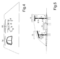
- FIG. 4 shows a further antenna 15 for a further radio service 2 in the near field of a first one Antenna 14 placed for a first radio service 1 with a narrowly tolerated antenna pattern.
- the picture shows a first antenna 14 as an antenna as shown in FIG DE 101 08 910 is specified.
- a further antenna 15 is an antenna as it is Inverted-F is known.
- To comply with the strict tolerance regulations of the Directional diagrams for the first antenna 14 are the flat elements of the further antenna 15 divided according to the rules specified in connection with FIG. 3b.
- FIG. 5 shows the situation of a first antenna 14 in connection with, in the near field, further antennas 15 designed as linear antennas.
- the others Antennas 15 are provided for radio services such as AMPS, GSM 900, PCS, GSM 1800 or UMTS.
- the directional diagram is this Antenna due to the presence of the further antenna 15 without the proposed measures intolerable.
- Parallel resonance circuits 16 separated are also the connections to these by the in the lower part of the spotlights Parallel resonance circuits 16 separated.
- the reactance circuit 8 is designed such that it has a zero at a frequency f 2 in the frequency range 9 of a further radio service 2 and a pole in the frequency range 6 of the first radio service 1, so that over the frequency bandwidth 21 a further radio service 2 has a sufficiently low-impedance 7 and a sufficiently high-impedance is given over the frequency bandwidth 13 of the first radio service 1.
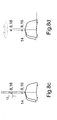
- FIG. 6a shows two possible forms of implementation of reactance circuits for the case that the frequency range 6 of the first radio service 1 is higher in frequency than the frequency range 9 of the further radio service 2. Corresponding forms of implementation are shown in FIG. 6b indicated for the reactance circuits 8 in the event that the frequency range 9 is higher than the frequency range 6.
- FIG. 6c shows implementation forms for reactance circuits 8, if any Radio services 2 are available, the frequency range 6 of the first radio service in its Frequency is between the two frequency ranges of the other radio services 2.
- Fig. 6d finally shows forms of implementation for the reactance circuits 8 when two frequency ranges 9 of the further radio services 2 are given, which are lower in frequency or, As in Fig. 6e, the frequency is higher than the frequency range 6 of the first radio service 1.
- the impedance X1 (f) forms a pole at the lower end of the monopole and is sufficiently high-impedance over the frequency bandwidth 13 of the first radio service 1 to practically not impair the directional diagram of the first antenna 14 , however, is chosen such that it is sufficiently low in the specified frequency ranges of PCS and AMPS.
- the reactance X2 (f) at the interruption points 10 in the upper third of the further antenna 15 is designed in a similar manner and, because of its high impedance, causes the upper part to be switched off in the PCS frequency range with full effectiveness in the AMPS frequency range.
- the impedance curve Z (f) shown in FIG. 7c at the base of the further antenna 15 shows the adaptation achieved in both telephone radio services.
- the combination antenna arrangement is in a further advantageous embodiment of the invention as a first antenna 14 for satellite broadcasting reception after SDARS standard as the first radio service 1 and for further antennas 15 according to the AMPS, and PCS standard designed as further radio services 2a and 2b.
- the first antenna is 14 according to the SDARS standard as an antenna on a substantially horizontal conductive Surface designed rotationally symmetrical with respect to its vertical center line.
- a vertical combined monopoly in its center line introduced the AMPS standard and the PCS standard. This is chosen in a suitable manner Interrupt points 10, as in FIG. 8c or FIG. 8d, with a suitable reactance circuit 8 wired.
- the monopoly has a roof capacity charged to avoid deformation of the directional diagram for the SDARS service with radial break points 10 in Fig. 8a for small diameters of the circular Roof plate is provided and in Fig. 8b circular interruption points 10 with Reactance circuits 8 are introduced.
- the first antenna is in the near field 14 for the first radio service 1, e.g. an SDARS antenna, as in FIG. 9 one on one rod-shaped plastic carrier attached AM / FM antenna designed.
- the length of such Antenna is usually chosen between 0.4m and 0.9m.
- the AM / FM monopole antenna made of a substantially wire-shaped conductor 25 educated.
- the high impedance of the antenna for frequency range 6 of the first radio service To manufacture 1 it will be used in the necessary intervals in an advantageous manner
- Coils 24 provided. These can be made from the same wire by tight winding or by one Meandering structures are designed in such a way that the resulting winding capacity forms a parallel resonant circuit 16 with the coil.
- the wire is a substantially the length of the rod-shaped plastic carrier 26 continuously wound wire coil, which one for the frequency range 6 of the first radio service 1 forms a sufficiently high-impedance structure.
Landscapes
- Variable-Direction Aerials And Aerial Arrays (AREA)
- Details Of Aerials (AREA)
Applications Claiming Priority (2)
| Application Number | Priority Date | Filing Date | Title |
|---|---|---|---|
| DE10304911.8A DE10304911B4 (de) | 2003-02-06 | 2003-02-06 | Kombinationsantennenanordnung für mehrere Funkdienste für Fahrzeuge |
| DE10304911 | 2003-02-06 |
Publications (2)
| Publication Number | Publication Date |
|---|---|
| EP1445832A2 true EP1445832A2 (fr) | 2004-08-11 |
| EP1445832A3 EP1445832A3 (fr) | 2007-05-23 |
Family
ID=32603185
Family Applications (1)
| Application Number | Title | Priority Date | Filing Date |
|---|---|---|---|
| EP04002306A Withdrawn EP1445832A3 (fr) | 2003-02-06 | 2004-02-03 | Combination d'antennes pour multiples radio services pour vehicules |
Country Status (5)
| Country | Link |
|---|---|
| US (1) | US6917340B2 (fr) |
| EP (1) | EP1445832A3 (fr) |
| JP (1) | JP2004242306A (fr) |
| KR (1) | KR20040071639A (fr) |
| DE (1) | DE10304911B4 (fr) |
Cited By (5)
| Publication number | Priority date | Publication date | Assignee | Title |
|---|---|---|---|---|
| WO2006018079A1 (fr) * | 2004-08-13 | 2006-02-23 | Rohde & Schwarz Gmbh & Co. Kg | Systeme d'antennes de reception comprenant plusieurs antennes actives |
| FR2925233A1 (fr) * | 2007-12-18 | 2009-06-19 | Thales Sa | Antenne active tres large bande pour radar passif. |
| EP2034557A3 (fr) * | 2007-09-06 | 2009-10-28 | Delphi Delco Electronics Europe GmbH | Antenne pour la réception de satellites |
| EP2226895A3 (fr) * | 2009-03-03 | 2010-12-15 | Delphi Delco Electronics Europe GmbH | Antenne pour la réception circulaire dans un sens de rotation de la polarisation de signaux radio par satellite rayonnés |
| US7936309B2 (en) | 2007-09-06 | 2011-05-03 | Delphi Delco Electronics Europe Gmbh | Antenna for satellite reception |
Families Citing this family (22)
| Publication number | Priority date | Publication date | Assignee | Title |
|---|---|---|---|---|
| DE10330087B3 (de) * | 2003-07-03 | 2005-01-20 | Kathrein-Werke Kg | Multifunktionsantenne |
| DE102006039357B4 (de) * | 2005-09-12 | 2018-06-28 | Heinz Lindenmeier | Antennendiversityanlage zum Funkempfang für Fahrzeuge |
| KR101292814B1 (ko) * | 2005-09-28 | 2013-08-02 | 한국전자통신연구원 | 공간 필터링된 수신 신호들의 최고 비율 조합 방법 및 이를위한 장치 |
| US7598824B2 (en) * | 2006-03-15 | 2009-10-06 | M/A-Com Technology Solutions Holdings, Inc. | Splitter/combiner circuit |
| US7420521B2 (en) * | 2007-01-08 | 2008-09-02 | Applied Radar Inc. | Wideband segmented dipole antenna |
| KR100848038B1 (ko) | 2007-02-14 | 2008-07-23 | 주식회사 이엠따블유안테나 | 다중대역 안테나 |
| WO2008120757A1 (fr) * | 2007-03-29 | 2008-10-09 | Kyocera Corporation | Dispositif sans fil portable |
| DE102007017478A1 (de) * | 2007-04-13 | 2008-10-16 | Lindenmeier, Heinz, Prof. Dr. Ing. | Empfangsanlage mit einer Schaltungsanordnung zur Unterdrückung von Umschaltstörungen bei Antennendiversity |
| JP2008283609A (ja) * | 2007-05-14 | 2008-11-20 | Kojima Press Co Ltd | 車載用アンテナシステム |
| DE102008031068A1 (de) * | 2007-07-10 | 2009-01-15 | Lindenmeier, Heinz, Prof. Dr. Ing. | Antennendiversityanlage für den relativ breitbandigen Funkempfang in Fahrzeugen |
| DE102007039914A1 (de) * | 2007-08-01 | 2009-02-05 | Lindenmeier, Heinz, Prof. Dr. Ing. | Antennendiversityanlage mit zwei Antennen für den Funkempfang in Fahrzeugen |
| US8816933B2 (en) * | 2008-10-23 | 2014-08-26 | Troll Systems Corporation | Directional diversity receive system |
| EP2209221B8 (fr) * | 2009-01-19 | 2019-01-16 | Fuba Automotive Electronics GmbH | Installation de réception destinée à la sommation de signaux d'antennes phasés |
| US8045592B2 (en) * | 2009-03-04 | 2011-10-25 | Laird Technologies, Inc. | Multiple antenna multiplexers, demultiplexers and antenna assemblies |
| DE102009023514A1 (de) * | 2009-05-30 | 2010-12-02 | Heinz Prof. Dr.-Ing. Lindenmeier | Antenne für zirkulare Polarisation mit einer leitenden Grundfläche |
| KR20110042656A (ko) * | 2009-10-19 | 2011-04-27 | 주식회사 에이스테크놀로지 | Lc 필터를 이용한 다중 대역 안테나 |
| DE102012003460A1 (de) * | 2011-03-15 | 2012-09-20 | Heinz Lindenmeier | Multiband-Empfangsantenne für den kombinierten Empfang von Satellitensignalen und terrestrisch ausgestrahlten Rundfunksignalen |
| DE102012014913A1 (de) | 2012-07-29 | 2014-05-15 | Heinz Lindenmeier | Elektrisch kleiner Strahler für vertikal polarisierte Funksignale |
| EP3221925B1 (fr) | 2014-11-18 | 2021-03-03 | CommScope Technologies LLC | Éléments de bande basse masqués pour réseaux rayonnants multibande |
| EP3091608B1 (fr) | 2015-05-04 | 2021-08-04 | TE Connectivity Germany GmbH | Système d'antenne et module d'antenne avec un élément parasite pour l'amélioration d'un diagramme de rayonnement |
| EP3091610B1 (fr) | 2015-05-08 | 2021-06-23 | TE Connectivity Germany GmbH | Système d'antenne et module d'antenne à réduction d'interférences entre des motifs rayonnants |
| EP3133695B1 (fr) * | 2015-08-18 | 2021-04-07 | TE Connectivity Nederland B.V. | Système d'antenne et module d'antenne à réduction d'interférences entre des motifs rayonnants |
Citations (5)
| Publication number | Priority date | Publication date | Assignee | Title |
|---|---|---|---|---|
| US2282292A (en) * | 1937-07-10 | 1942-05-05 | Ernest V Amy | All wave radio receiving system |
| US5543815A (en) * | 1990-11-30 | 1996-08-06 | Hughes Aircraft Company | Shielding screen for integration of multiple antennas |
| WO1998026471A2 (fr) * | 1996-11-26 | 1998-06-18 | Ball Aerospace & Technologies Corp. | Antenne vitreuse |
| EP0963004A2 (fr) * | 1998-06-04 | 1999-12-08 | Matsushita Electric Industrial Co., Ltd. | Antenne monopole |
| EP1239543A1 (fr) * | 2001-02-23 | 2002-09-11 | FUBA Automotive GmbH & Co. KG | Antenne plate pour communication mobile via satellites |
Family Cites Families (11)
| Publication number | Priority date | Publication date | Assignee | Title |
|---|---|---|---|---|
| JPS5513524A (en) * | 1978-07-13 | 1980-01-30 | Denki Kogyo Kk | Medium wave antenna for multi-wave |
| US4443803A (en) * | 1980-04-23 | 1984-04-17 | The United States Of America As Represented By The Secretary Of The Army | Lossy matching for broad bonding low profile small antennas |
| US5829007A (en) * | 1993-06-24 | 1998-10-27 | Discovision Associates | Technique for implementing a swing buffer in a memory array |
| US5610620A (en) * | 1995-05-19 | 1997-03-11 | Comant Industries, Inc. | Combination antenna |
| DE19740254A1 (de) | 1996-10-16 | 1998-04-23 | Lindenmeier Heinz | Funkantennen-Anordnung und Patchantenne auf der Fensterscheibe eines Kraftfahrzeuges |
| JP2000077923A (ja) * | 1998-09-01 | 2000-03-14 | Nippon Antenna Co Ltd | 車載用アンテナ |
| US6078295A (en) * | 1999-02-24 | 2000-06-20 | Ericsson Inc. | Tri-band antenna |
| US6658056B1 (en) * | 1999-03-30 | 2003-12-02 | Sony Corporation | Digital video decoding, buffering and frame-rate converting method and apparatus |
| US6229495B1 (en) * | 1999-08-06 | 2001-05-08 | Bae Systems Advanced Systems | Dual-point-feed broadband whip antenna |
| US6891894B1 (en) * | 1999-11-18 | 2005-05-10 | Lg Electronics Inc. | Method for decoding and displaying digital broadcasting signals |
| US7292772B2 (en) * | 2000-05-29 | 2007-11-06 | Sony Corporation | Method and apparatus for decoding and recording medium for a coded video stream |
-
2003
- 2003-02-06 DE DE10304911.8A patent/DE10304911B4/de not_active Expired - Fee Related
-
2004
- 2004-02-03 US US10/770,652 patent/US6917340B2/en not_active Expired - Lifetime
- 2004-02-03 JP JP2004026231A patent/JP2004242306A/ja active Pending
- 2004-02-03 EP EP04002306A patent/EP1445832A3/fr not_active Withdrawn
- 2004-02-05 KR KR1020040007471A patent/KR20040071639A/ko not_active Application Discontinuation
Patent Citations (5)
| Publication number | Priority date | Publication date | Assignee | Title |
|---|---|---|---|---|
| US2282292A (en) * | 1937-07-10 | 1942-05-05 | Ernest V Amy | All wave radio receiving system |
| US5543815A (en) * | 1990-11-30 | 1996-08-06 | Hughes Aircraft Company | Shielding screen for integration of multiple antennas |
| WO1998026471A2 (fr) * | 1996-11-26 | 1998-06-18 | Ball Aerospace & Technologies Corp. | Antenne vitreuse |
| EP0963004A2 (fr) * | 1998-06-04 | 1999-12-08 | Matsushita Electric Industrial Co., Ltd. | Antenne monopole |
| EP1239543A1 (fr) * | 2001-02-23 | 2002-09-11 | FUBA Automotive GmbH & Co. KG | Antenne plate pour communication mobile via satellites |
Non-Patent Citations (1)
| Title |
|---|
| ARNAUD J A ET AL: "RESONANT-GRID QUASI-OPTICAL DIPLEXERS" BELL SYSTEM TECHNICAL JOURNAL, AMERICAN TELEPHONE AND TELEGRAPH CO. NEW YORK, US, Bd. 54, Nr. 2, Februar 1975 (1975-02), Seiten 263-283, XP002030965 * |
Cited By (9)
| Publication number | Priority date | Publication date | Assignee | Title |
|---|---|---|---|---|
| WO2006018079A1 (fr) * | 2004-08-13 | 2006-02-23 | Rohde & Schwarz Gmbh & Co. Kg | Systeme d'antennes de reception comprenant plusieurs antennes actives |
| US7456800B2 (en) | 2004-08-13 | 2008-11-25 | Rohde & Schwarz Gmbh & Co. Kg | Receiving antenna system comprising several active antennae |
| EP2034557A3 (fr) * | 2007-09-06 | 2009-10-28 | Delphi Delco Electronics Europe GmbH | Antenne pour la réception de satellites |
| US7936309B2 (en) | 2007-09-06 | 2011-05-03 | Delphi Delco Electronics Europe Gmbh | Antenna for satellite reception |
| FR2925233A1 (fr) * | 2007-12-18 | 2009-06-19 | Thales Sa | Antenne active tres large bande pour radar passif. |
| WO2009077529A2 (fr) * | 2007-12-18 | 2009-06-25 | Thales | Antenne active tres large bande pour radar passif |
| WO2009077529A3 (fr) * | 2007-12-18 | 2010-04-08 | Thales | Antenne active tres large bande pour radar passif |
| EP2226895A3 (fr) * | 2009-03-03 | 2010-12-15 | Delphi Delco Electronics Europe GmbH | Antenne pour la réception circulaire dans un sens de rotation de la polarisation de signaux radio par satellite rayonnés |
| US8537063B2 (en) | 2009-03-03 | 2013-09-17 | Delphi Delco Electronics Europe Gmbh | Antenna for reception of satellite radio signals emitted circularly, in a direction of rotation of the polarization |
Also Published As
| Publication number | Publication date |
|---|---|
| DE10304911B4 (de) | 2014-10-09 |
| US6917340B2 (en) | 2005-07-12 |
| EP1445832A3 (fr) | 2007-05-23 |
| JP3126610U (ja) | 2006-11-02 |
| DE10304911A1 (de) | 2004-08-19 |
| JP2004242306A (ja) | 2004-08-26 |
| US20040183737A1 (en) | 2004-09-23 |
| KR20040071639A (ko) | 2004-08-12 |
Similar Documents
| Publication | Publication Date | Title |
|---|---|---|
| EP1445832A2 (fr) | Combination d'antennes pour multiples radio services pour vehicules | |
| EP1619752B1 (fr) | Module d'antenne | |
| DE102007055323B4 (de) | Finnenförmiges Multiband Antennenmodul für Fahrzeuge | |
| DE60121470T2 (de) | Antennenanordnung | |
| DE3789161T2 (de) | Antenne für Gerät zur drahtlosen Nachrichtenübertragung. | |
| DE69835246T2 (de) | Doppelresonanzantennenstruktur für mehrere Frequenzbereiche | |
| DE69724253T2 (de) | Mäanderförmige antennenanordnung | |
| EP1829158B1 (fr) | Structure d'antenne disque unipolaire | |
| DE69804023T2 (de) | Antenne | |
| EP1493206B1 (fr) | Antenne a double bande | |
| EP2664025B1 (fr) | Antenne de réception multibande pour la réception combinée de signaux satellites et de signaux radiophoniques à émission terrestre | |
| EP0841715B1 (fr) | Antenne plate | |
| DE102008007258A1 (de) | Mehrband-Antenne sowie mobiles Kommunikationsendgerät, welches diese aufweist | |
| EP0952625A2 (fr) | Antenne pour plusieurs services radio | |
| EP1955406B1 (fr) | Antenne omnidirectionnelle multibande | |
| EP1323207B1 (fr) | Telephone mobile a antenne multibande | |
| DE19929689A1 (de) | Integrierbare Dualband-Antenne | |
| EP3382795A1 (fr) | Antenne destinée à recevoir des signaux satellites polarisés circulairement pour la navigation par satellite sur un véhicule | |
| EP3474374B1 (fr) | Dispositif d'antenne pour signaux satellites polarisés circulairement sur un véhicule | |
| EP1297590A1 (fr) | Antenne fendue | |
| DE102017010514A1 (de) | Empfangsantenne für die Satellitennavigation auf einem Fahrzeug | |
| DE10331281A1 (de) | Antenne mit geneigter Strahlerfläche | |
| EP3827478B1 (fr) | Antenne à carte de circuit imprimé | |
| DE19858090A1 (de) | Doppelbandantenne und Verfahren zu deren Herstellung | |
| EP2756550B1 (fr) | Antenne multibande pour véhicule automobile |
Legal Events
| Date | Code | Title | Description |
|---|---|---|---|
| PUAI | Public reference made under article 153(3) epc to a published international application that has entered the european phase |
Free format text: ORIGINAL CODE: 0009012 |
|
| AK | Designated contracting states |
Kind code of ref document: A2 Designated state(s): AT BE BG CH CY CZ DE DK EE ES FI FR GB GR HU IE IT LI LU MC NL PT RO SE SI SK TR |
|
| AX | Request for extension of the european patent |
Extension state: AL LT LV MK |
|
| PUAL | Search report despatched |
Free format text: ORIGINAL CODE: 0009013 |
|
| AK | Designated contracting states |
Kind code of ref document: A3 Designated state(s): AT BE BG CH CY CZ DE DK EE ES FI FR GB GR HU IE IT LI LU MC NL PT RO SE SI SK TR |
|
| AX | Request for extension of the european patent |
Extension state: AL LT LV MK |
|
| 17P | Request for examination filed |
Effective date: 20070531 |
|
| 17Q | First examination report despatched |
Effective date: 20071129 |
|
| AKX | Designation fees paid |
Designated state(s): AT BE BG CH CY CZ DE DK EE ES FI FR GB GR HU IE IT LI LU MC NL PT RO SE SI SK TR |
|
| RAP1 | Party data changed (applicant data changed or rights of an application transferred) |
Owner name: DELPHI DELCO ELECTRONICS EUROPE GMBH |
|
| RAP1 | Party data changed (applicant data changed or rights of an application transferred) |
Owner name: DELPHI DELCO ELECTRONICS EUROPE GMBH |
|
| STAA | Information on the status of an ep patent application or granted ep patent |
Free format text: STATUS: THE APPLICATION IS DEEMED TO BE WITHDRAWN |
|
| 18D | Application deemed to be withdrawn |
Effective date: 20160901 |