EP1445077A1 - Machine à trancher à action double et procédé d'utilisation - Google Patents
Machine à trancher à action double et procédé d'utilisation Download PDFInfo
- Publication number
- EP1445077A1 EP1445077A1 EP03380021A EP03380021A EP1445077A1 EP 1445077 A1 EP1445077 A1 EP 1445077A1 EP 03380021 A EP03380021 A EP 03380021A EP 03380021 A EP03380021 A EP 03380021A EP 1445077 A1 EP1445077 A1 EP 1445077A1
- Authority
- EP
- European Patent Office
- Prior art keywords
- disk
- workpiece
- supporting surface
- cutting
- cutting edge
- Prior art date
- Legal status (The legal status is an assumption and is not a legal conclusion. Google has not performed a legal analysis and makes no representation as to the accuracy of the status listed.)
- Withdrawn
Links
Images


Classifications
-
- B—PERFORMING OPERATIONS; TRANSPORTING
- B26—HAND CUTTING TOOLS; CUTTING; SEVERING
- B26D—CUTTING; DETAILS COMMON TO MACHINES FOR PERFORATING, PUNCHING, CUTTING-OUT, STAMPING-OUT OR SEVERING
- B26D1/00—Cutting through work characterised by the nature or movement of the cutting member or particular materials not otherwise provided for; Apparatus or machines therefor; Cutting members therefor
- B26D1/01—Cutting through work characterised by the nature or movement of the cutting member or particular materials not otherwise provided for; Apparatus or machines therefor; Cutting members therefor involving a cutting member which does not travel with the work
- B26D1/12—Cutting through work characterised by the nature or movement of the cutting member or particular materials not otherwise provided for; Apparatus or machines therefor; Cutting members therefor involving a cutting member which does not travel with the work having a cutting member moving about an axis
- B26D1/14—Cutting through work characterised by the nature or movement of the cutting member or particular materials not otherwise provided for; Apparatus or machines therefor; Cutting members therefor involving a cutting member which does not travel with the work having a cutting member moving about an axis with a circular cutting member, e.g. disc cutter
- B26D1/143—Cutting through work characterised by the nature or movement of the cutting member or particular materials not otherwise provided for; Apparatus or machines therefor; Cutting members therefor involving a cutting member which does not travel with the work having a cutting member moving about an axis with a circular cutting member, e.g. disc cutter rotating about a stationary axis
-
- B—PERFORMING OPERATIONS; TRANSPORTING
- B26—HAND CUTTING TOOLS; CUTTING; SEVERING
- B26D—CUTTING; DETAILS COMMON TO MACHINES FOR PERFORATING, PUNCHING, CUTTING-OUT, STAMPING-OUT OR SEVERING
- B26D1/00—Cutting through work characterised by the nature or movement of the cutting member or particular materials not otherwise provided for; Apparatus or machines therefor; Cutting members therefor
- B26D1/01—Cutting through work characterised by the nature or movement of the cutting member or particular materials not otherwise provided for; Apparatus or machines therefor; Cutting members therefor involving a cutting member which does not travel with the work
- B26D1/12—Cutting through work characterised by the nature or movement of the cutting member or particular materials not otherwise provided for; Apparatus or machines therefor; Cutting members therefor involving a cutting member which does not travel with the work having a cutting member moving about an axis
- B26D1/14—Cutting through work characterised by the nature or movement of the cutting member or particular materials not otherwise provided for; Apparatus or machines therefor; Cutting members therefor involving a cutting member which does not travel with the work having a cutting member moving about an axis with a circular cutting member, e.g. disc cutter
- B26D1/157—Cutting through work characterised by the nature or movement of the cutting member or particular materials not otherwise provided for; Apparatus or machines therefor; Cutting members therefor involving a cutting member which does not travel with the work having a cutting member moving about an axis with a circular cutting member, e.g. disc cutter rotating about a movable axis
- B26D1/18—Cutting through work characterised by the nature or movement of the cutting member or particular materials not otherwise provided for; Apparatus or machines therefor; Cutting members therefor involving a cutting member which does not travel with the work having a cutting member moving about an axis with a circular cutting member, e.g. disc cutter rotating about a movable axis mounted on a movable carriage
-
- B—PERFORMING OPERATIONS; TRANSPORTING
- B26—HAND CUTTING TOOLS; CUTTING; SEVERING
- B26D—CUTTING; DETAILS COMMON TO MACHINES FOR PERFORATING, PUNCHING, CUTTING-OUT, STAMPING-OUT OR SEVERING
- B26D5/00—Arrangements for operating and controlling machines or devices for cutting, cutting-out, stamping-out, punching, perforating, or severing by means other than cutting
-
- B—PERFORMING OPERATIONS; TRANSPORTING
- B26—HAND CUTTING TOOLS; CUTTING; SEVERING
- B26D—CUTTING; DETAILS COMMON TO MACHINES FOR PERFORATING, PUNCHING, CUTTING-OUT, STAMPING-OUT OR SEVERING
- B26D2210/00—Machines or methods used for cutting special materials
- B26D2210/02—Machines or methods used for cutting special materials for cutting food products, e.g. food slicers
-
- B—PERFORMING OPERATIONS; TRANSPORTING
- B26—HAND CUTTING TOOLS; CUTTING; SEVERING
- B26D—CUTTING; DETAILS COMMON TO MACHINES FOR PERFORATING, PUNCHING, CUTTING-OUT, STAMPING-OUT OR SEVERING
- B26D5/00—Arrangements for operating and controlling machines or devices for cutting, cutting-out, stamping-out, punching, perforating, or severing by means other than cutting
- B26D5/08—Means for actuating the cutting member to effect the cut
Definitions
- This invention refers to a dual action slicing device and more concretely slicing device provided with a cutting disk adapted and driven for cutting in both rotation directions.
- This invention also refers to a dual action slicing process using such device.
- the device and process of this invention is specially applicable to slicing relatively soft and/or lightweight products and it is useful for example in cork, foamed polymers, light metallic alloys, etc. industries and in the sector of foods, pork's produces and pastries, among others.
- Slicing devices are known for cutting slices out of different kinds of materials, that is to say, more or less thin, wide and elongated portions obtained by successive parallel cuts of a piece of material, herein called workpiece, from one end to the other.
- workpiece a piece of material
- Such machines comprise a supporting surface, a cutting disk located with relation to such supporting surface and a motor connected to the cutting disk to make it to rotate.
- the workpiece is moving on the supporting surface in a cutting direction parallel to the plane of the disk, and interfering with it, until the disk cutting edge cuts a slice from one end of the piece to the other.
- the workpiece remains stationary and it is the disk which is moving.
- an essential characteristic for obtaining a good cut in this kind of machines is that the disk cutting edge is adapted for at least cutting in a given rotation direction and that, at the side of the disk where the cutting edge impinges against the workpiece, this rotation direction is towards the supporting surface. This is so because the cutting edge impinging against the working surface in such rotation direction towards the supporting surface tends to press the workpiece against the supporting surface and cooperates in pulling in such cutting direction. This effect is improved if the axis of the disk is located above the supporting plane. On the contrary, if the cutting edge impinge against the workpiece in the opposite direction of rotation, it would tend to lift and vibrate the end of the workpiece in contact with the disk and could cause a defective cut and even break the piece.
- the disk is constantly driven in a single rotation direction to which the disk is fit and the cut is carried out by displacing the workpiece in a single suitable cutting direction.
- the workpiece has to come back to its initial position and, after it moves forwards in a direction perpendicular to the plane of the disk to determine the thickness wished for the following slice, repeat the displacement in such single suitable cutting direction to newly slice.
- This backwards displacement means a loss of time and power which increases the cutting operations costs.
- the utility model ES-A-1029673 discloses a machine for cutting cork including above described characteristics.
- the object of this invention is to overcome former and other drawbacks providing a slicing device and process provided with a cutting disk adapted and driven for cutting slices out of a workpiece in the two opposite cutting directions parallel to the disk plane by means of a to and fro displacement of the workpiece.
- a dual action slicing device of the kind which comprises a supporting surface, a rotating disk, provided with at least a cutting edge arranged with relation to such supporting surface and adapted for cutting in at least a first rotation direction towards such supporting surface and a motor connected to such disk for driving such cutting edge at least in such first rotation direction in order to cut a slice out of at least a workpiece by means of a relative displacement with interference between the cutting edge and such workpiece on the supporting surface in a first cutting direction, control means being provided for controlling the disk drive.
- the device is characterized in that the disk cutting edge is adapted for in addition cutting in an opposite second rotation direction towards the supporting surface and such motor is connected to such disk for in addition driving such cutting edge in such second rotation direction in order to cut a slice out of a workpiece which is at least one, by a relative displacement with interference between the cutting edge and such workpiece on the supporting surface in an opposite second cutting direction, such control means being adapted for alternately changing the first and second disk rotation directions.
- the control means alternately change the first and second disk rotation directions in combination with corresponding change in such first and second disk cutting directions in relation with the workpiece to carry out successive cuts in both directions, other relative displacements occurring intermittently between the disk and the workpiece in a forwards direction when the disk and the workpiece are not in contact, to determine the width of the slices obtained.
- the device incorporates a collecting and a sorting systems for such slices obtained by cutting the workpiece.
- the collecting system comprises a conveyor belt having an adjustable speed and a reversible displacement direction which can occur in a direction either parallel to the plane of the disk or perpendicular to it.
- the sorting system comprises shifter elements selectively driven for expelling from the conveyor belt the slices in order to sort them according to the width thereof resulting from the cut.
- the drive of such shifting elements as well as the displacements of the conveyor belt are the response to orders coming from programmable control means.
- the device can have two basic configurations.
- the disk is stationary with respect to the supporting surface and the workpiece carries out such displacements in the first and second cutting directions and in such forwards direction with respect to the supporting surface.
- First and second pulling means associated to the supporting surface and driven by driving means carry out the displacements of the workpiece on the supporting surface in the fist and second cutting directions and in a forwards direction, respectively.
- cutting and forward displacements as well as the changes of the disk rotation direction and driving the conveyor belt and the pushers is carried out under the centralized orders of such control means according to preprogrammed operations.
- the workpiece is stationary with respect to the supporting surface and the disk carries out the said displacements in the fist and the second cutting directions and in such forwards direction with respect to the supporting surface, other configurations being possible resulting from matching the two former ones.
- this invention provides a dual action slicing process which comprises the steps of:
- the dual action slicing device comprises a frame 10 which supports a supporting surface 1.
- a rotating disk 2 is mounted so that it can rotate in both directions.
- Such disk 2 has a cutting edge 2a arranged with relation to such supporting surface 1 and adapted for cutting in both rotating directions S1 and S2.
- a motor 3 is connected to such disk 2 either directly or by means of a drive, such as a belt 12.
- Control means are connected with such motor for alternately changing such rotation directions S1 and S2.
- first pulling means 13 are mounted for displacing a workpiece (designed with reference P in Fig.
- Second pulling means 14 are adapted for displacing such workpiece P sliding on such supporting surface 1 in a forwards direction A perpendicular to the plane of the cutting disk 2.
- the first and second pulling means 13, 14 comprise a first slide 13 mounted so that it can move on tracks arranged on such top part 11 of the frame 10 in the cutting directions D1, D2 and a second slide 14 mounted so that it can move on tracks arranged on such first slide 13 in the forwards direction A. From such second slide 14 a telescopic arm 15 is extending downwards which ends in a catching shaped 16.
- Such first and second slides 13, 15 as well as the telescopic arm 16, are driven by conventional means under the orders of such control means to carry out the displacements of the workpiece P on the supporting surface 1 in the first and second cutting directions D1, D2 and in such forwards direction A, respectively, combined with such alternate changes between the first and second rotation directions S1, S2 of the disk 2 according to a program for implementing the process of this invention which is described below with relation to Fig. 5 to 8.
- the motor 3 is an electric motor or an electric back-geared motor and can be connected to the disk 2 either directly or through a drive.
- the said control means can operate to change the rotation direction of such electric motor 3, which is carried out in a sufficiently quick way through the use of a PLC or, alternatively, when such motor 3 is connected to disk 2 through a drive adapted, such control means can operate on such drive for changing the rotation direction of the disk 2.
- An as lightweight as possible disk 2 cooperates in the quickness of the rotation direction change.
- the disk 2 is adapted for cutting in both rotation directions S1 and S2.
- Fig. 3 shows a disk 2 suitable for relatively soft materials such as cork, pastries, pork's produces and the like, in which the cutting edge 2a is smooth and sharp as a circular blade.
- Fig. 4 shows a disk 2 suitable for hard material, for which the cutting edge 2a comprises a plurality of teeth, each of which is symmetric with respect to a radius of the disk.
- the cutting edge 2a comprises a plurality of teeth, each of which is symmetric with respect to a radius of the disk.
- the cutting edge 2a comprises a plurality of teeth, each of which is symmetric with respect to a radius of the disk.
- the cutting edge 2a comprises a plurality of teeth, each of which is symmetric with respect to a radius of the disk.
- the cutting edge 2a comprises a plurality of teeth, each of which is symmetric with respect to a radius of the disk.
- the cutting edge 2a comprises a plurality of teeth, each of
- the disk 2 is stationary and the workpiece P is the one which moves
- the workpiece P is placed stationary with respect to the supporting surface 1 and the disk 2 carries out such displacements in the first and second cutting directions D1, D2 and in such forwards direction A with respect to the supporting direction 1. It is also possible to have a configuration (not shown which matches the displacements of the workpiece P with the displacements of the disk 2.
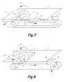
- the device in addition incorporates a collecting system and a sorting system (Fig. 7 and 8) for the slices R obtained by cutting the workpiece P.
- the said collecting system comprises a conveyor belt 4 having an adjustable speed and reversible displacement direction, which, in the example of embodiment of Fig. 1, moves in a direction parallel to the plane of the disk 2.
- the conveyor belt 4, which is shown horizontal, although, depending on the application, it could be slightly inclined, is driven by an electric motor 17 through a drive such as a belt 18.
- the said sorting system comprises shifting elements 5, as blades or gates (of which Fig. 1 and 5 to 8 only shows one for a clearer drawing) mounted hinged and successively arranged close to the conveyor belt 4.
- the shifting elements 5 are selectively driven by means, for example, of respective fluid dynamic cylinders 18 or other equivalent driving members for expelling from the conveyor belt 4 the slices R (see also Fig. 8) and make them drop in different containers depending on their width resulting from the cut in order to sort them.
- the conveyor belt and such shifting elements 5 are driven as a response to orders coming from the programmable control means and coordinated with the device cutting actions.
- the conveyor belt 4 moves in a direction perpendicular to the plane of the disk 2 and is located at a level lower than the supporting surface 1 so that it starts under it.
- the conveyor belt 4 thus arranged has a relatively great width which in some cases can be approximately equal to the width of the supporting surface 1.
- P2 for example, pieces of sausages
- the catching configuration 16 it is possible to group several units of the product to be cut P2 (for example, pieces of sausages) with the catching configuration 16 and to jointly move them by means of the telescopic arm 15 joined to the slides 13, 14 in D1, D2 and A, directions according to the process described below with relation to Fig. 5 to 8, in order to cut at each pass a plurality of slices C2, which directly fall on trays 19 which move on conveyor belts 4.
- the process comprises, first, the step of a) arrange a rotating disk 2 provided with a cutting edge 2a with relation to a supporting surface 1 and then, b) operate such disk 2 for moving such cutting edge 2a in a first rotation direction S1 towards such supporting surface 1 and towards a workpiece P arranged on the supporting surface 1 at one side of the disk 2 (Fig. 5). Then, c) carry out a relative displacement with interference between the disk 2 and a workpiece P on the supporting surface 1 in a first cutting direction D1 in order to cut a slice out of such workpiece P (Fig. 6).
- the workpiece P passes to occupy a position on the supporting surface 1 on the opposite side of the disk 2.
- d) carry out a relative displacement between the disk 2 and the workpiece P in a forwards direction A when the disk 2 and the workpiece P are not contacting to each other after such cut (Fig. 7) and thereafter or simultaneously, e) operate such disk 2 for moving such cutting edge 2a in an opposite second rotation direction S2, towards such supporting direction 1 and towards the workpiece P.
- c) to carry out another relative displacement with interference between the disk 2 and the workpiece P on the supporting surface 1 in an opposite second cutting direction D2 in order to carry out another cut in such workpiece P (Fig.
- first and second cutting directions D1, D2 are substantially parallel to the plane of the disc 2, or which is the same, perpendicular to its spin axis and that the approach and impingement of the workpiece P on the cutting edge 2a is carried out by the side of the disk 2 in which the cutting edge 2a is moving towards the supporting surface 1.
- This tends to press the workpiece against the supporting surface preventing vibrations and hammering thereof and cooperate to pull it in the corresponding cutting direction D1 or D2, and this is the reason why the process comprises changing the rotation direction S1, S2 of the disk 2 after each cutting operation in order to take profit of the workpiece displacement in both cutting directions D1, D2.
- one of the two displacements is always idle the device and the process of this invention provide a virtually doubled productivity.
Priority Applications (1)
| Application Number | Priority Date | Filing Date | Title |
|---|---|---|---|
| EP03380021A EP1445077A1 (fr) | 2003-02-05 | 2003-02-05 | Machine à trancher à action double et procédé d'utilisation |
Applications Claiming Priority (1)
| Application Number | Priority Date | Filing Date | Title |
|---|---|---|---|
| EP03380021A EP1445077A1 (fr) | 2003-02-05 | 2003-02-05 | Machine à trancher à action double et procédé d'utilisation |
Publications (1)
| Publication Number | Publication Date |
|---|---|
| EP1445077A1 true EP1445077A1 (fr) | 2004-08-11 |
Family
ID=32605466
Family Applications (1)
| Application Number | Title | Priority Date | Filing Date |
|---|---|---|---|
| EP03380021A Withdrawn EP1445077A1 (fr) | 2003-02-05 | 2003-02-05 | Machine à trancher à action double et procédé d'utilisation |
Country Status (1)
| Country | Link |
|---|---|
| EP (1) | EP1445077A1 (fr) |
Cited By (7)
| Publication number | Priority date | Publication date | Assignee | Title |
|---|---|---|---|---|
| ES2229954A1 (es) * | 2004-10-08 | 2005-04-16 | Jose Luis Godoy Varo | Dispositivo y procedimiento de gestion y control para un aparato automatico de manipulacion y tratamiento, aplicable a placas de corcho natural. |
| ES2229953A1 (es) * | 2004-10-08 | 2005-04-16 | Jose Luis Godoy Varo | Aparato automatico para manipulacion y corte, aplicable a placas de corcho natural en bruto. |
| ES2296433A1 (es) * | 2004-10-08 | 2008-04-16 | Jose Luis Godoy Varo | Dispositivo y procedimiento de tope de guia variable para rebanadora de placas de corcho. |
| WO2009083485A1 (fr) * | 2007-12-27 | 2009-07-09 | Hochland Natec Gmbh | Découpe d'une masse de denrée alimentaire molle |
| DE102011017227A1 (de) * | 2011-04-15 | 2012-10-18 | Weber Maschinenbau Gmbh Breidenbach | Verfahren zum Aufschneiden von Lebensmittelprodukten |
| DE102012210709A1 (de) * | 2012-06-25 | 2014-01-02 | Weber Maschinenbau Gmbh Breidenbach | Portionierung von Scheiben |
| CN112454492A (zh) * | 2020-11-09 | 2021-03-09 | 湖南知味大师食品有限公司 | 一种西式培根加工用切片机 |
Citations (4)
| Publication number | Priority date | Publication date | Assignee | Title |
|---|---|---|---|---|
| DE548097C (de) * | 1931-04-26 | 1932-04-13 | Alexanderwerk A Von Der Nahmer | Aufschnittschneidemaschine |
| US4583435A (en) * | 1982-10-22 | 1986-04-22 | Natec Reich, Summer Gmbh. & Co. Kg. | Slab-cutting machine |
| EP0437643A1 (fr) * | 1990-01-13 | 1991-07-24 | Kurt Warnke | Dispositif pour couper des produits alimentaires avec un couteau rotatif |
| US6196097B1 (en) * | 1999-05-07 | 2001-03-06 | Hormel Foods, Llc | Bacon slicer system |
-
2003
- 2003-02-05 EP EP03380021A patent/EP1445077A1/fr not_active Withdrawn
Patent Citations (4)
| Publication number | Priority date | Publication date | Assignee | Title |
|---|---|---|---|---|
| DE548097C (de) * | 1931-04-26 | 1932-04-13 | Alexanderwerk A Von Der Nahmer | Aufschnittschneidemaschine |
| US4583435A (en) * | 1982-10-22 | 1986-04-22 | Natec Reich, Summer Gmbh. & Co. Kg. | Slab-cutting machine |
| EP0437643A1 (fr) * | 1990-01-13 | 1991-07-24 | Kurt Warnke | Dispositif pour couper des produits alimentaires avec un couteau rotatif |
| US6196097B1 (en) * | 1999-05-07 | 2001-03-06 | Hormel Foods, Llc | Bacon slicer system |
Cited By (10)
| Publication number | Priority date | Publication date | Assignee | Title |
|---|---|---|---|---|
| ES2229954A1 (es) * | 2004-10-08 | 2005-04-16 | Jose Luis Godoy Varo | Dispositivo y procedimiento de gestion y control para un aparato automatico de manipulacion y tratamiento, aplicable a placas de corcho natural. |
| ES2229953A1 (es) * | 2004-10-08 | 2005-04-16 | Jose Luis Godoy Varo | Aparato automatico para manipulacion y corte, aplicable a placas de corcho natural en bruto. |
| ES2296433A1 (es) * | 2004-10-08 | 2008-04-16 | Jose Luis Godoy Varo | Dispositivo y procedimiento de tope de guia variable para rebanadora de placas de corcho. |
| WO2009083485A1 (fr) * | 2007-12-27 | 2009-07-09 | Hochland Natec Gmbh | Découpe d'une masse de denrée alimentaire molle |
| US9237738B2 (en) | 2007-12-27 | 2016-01-19 | Hochland Natec Gmbh | Cutting of a soft food mass |
| US10561116B2 (en) | 2007-12-27 | 2020-02-18 | Hochland Natec Gmbh | Cutting of a soft food mass |
| DE102011017227A1 (de) * | 2011-04-15 | 2012-10-18 | Weber Maschinenbau Gmbh Breidenbach | Verfahren zum Aufschneiden von Lebensmittelprodukten |
| US8991289B2 (en) | 2011-04-15 | 2015-03-31 | Weber Maschinenbau Gmbh Breidenbach | Method for the slicing of food products |
| DE102012210709A1 (de) * | 2012-06-25 | 2014-01-02 | Weber Maschinenbau Gmbh Breidenbach | Portionierung von Scheiben |
| CN112454492A (zh) * | 2020-11-09 | 2021-03-09 | 湖南知味大师食品有限公司 | 一种西式培根加工用切片机 |
Similar Documents
| Publication | Publication Date | Title |
|---|---|---|
| CN101670467B (zh) | 带有双摆动刀片的、用于切割管件的立式机具以及借助于该机具的切割方法 | |
| CN114504112B (zh) | 一种桔子分瓣机 | |
| CH710403A2 (de) | Aufschnittschneidmaschine. | |
| EP1445077A1 (fr) | Machine à trancher à action double et procédé d'utilisation | |
| CN109676654B (zh) | 一种农产品切根机 | |
| EP1537966A3 (fr) | Dispostif de coupe de pains ainsi que d'autres produits de boulangerie | |
| CN104684702A (zh) | 连续按份量生产的装置及其方法 | |
| EP2777897B1 (fr) | Trancheuse industrielle | |
| US20070084324A1 (en) | Slicer for circular formed bakery products | |
| US6176370B1 (en) | Endless conveyor having quick release slats | |
| WO2003051589A1 (fr) | Cisailles de tambour rotatif helicoide | |
| US3972254A (en) | Cutting mechanism and method for cutting or slicing strips fed thereto | |
| US1955004A (en) | Severing apparatus | |
| JP2001088087A (ja) | 上下往復動型スライサ | |
| EP1005962A3 (fr) | Support pour le couteau d'une machine de coupe, monté de façon excentrée sur des disques synchronisés en rotation | |
| JP3118417B2 (ja) | 長葱切断装置 | |
| US4497233A (en) | Hotdog roll slicer | |
| CN108098877B (zh) | 一种链轨式球状农副果品切片机 | |
| US6543325B1 (en) | Drive system for food slicing machine | |
| JP3816412B2 (ja) | カッティング方法 | |
| CN215302742U (zh) | 一种推料结构、送料装置以及斜切肉片机 | |
| US1976865A (en) | Stacker | |
| CN220784036U (zh) | 一种切刀气缸 | |
| US3858470A (en) | French and italian bread slicer | |
| US3302502A (en) | Method and apparatus for dicing material |
Legal Events
| Date | Code | Title | Description |
|---|---|---|---|
| PUAI | Public reference made under article 153(3) epc to a published international application that has entered the european phase |
Free format text: ORIGINAL CODE: 0009012 |
|
| AK | Designated contracting states |
Kind code of ref document: A1 Designated state(s): AT BE BG CH CY CZ DE DK EE ES FI FR GB GR HU IE IT LI LU MC NL PT SE SI SK TR |
|
| AX | Request for extension of the european patent |
Extension state: AL LT LV MK RO |
|
| AKX | Designation fees paid | ||
| STAA | Information on the status of an ep patent application or granted ep patent |
Free format text: STATUS: THE APPLICATION HAS BEEN WITHDRAWN |
|
| REG | Reference to a national code |
Ref country code: DE Ref legal event code: 8566 |
|
| 18W | Application withdrawn |
Effective date: 20050504 |