EP1444917B1 - Device for storing and applying a product - Google Patents
Device for storing and applying a product Download PDFInfo
- Publication number
- EP1444917B1 EP1444917B1 EP04290289A EP04290289A EP1444917B1 EP 1444917 B1 EP1444917 B1 EP 1444917B1 EP 04290289 A EP04290289 A EP 04290289A EP 04290289 A EP04290289 A EP 04290289A EP 1444917 B1 EP1444917 B1 EP 1444917B1
- Authority
- EP
- European Patent Office
- Prior art keywords
- ring
- fact
- neck
- applicator
- relief
- Prior art date
- Legal status (The legal status is an assumption and is not a legal conclusion. Google has not performed a legal analysis and makes no representation as to the accuracy of the status listed.)
- Expired - Lifetime
Links
- 238000004519 manufacturing process Methods 0.000 claims abstract description 5
- 238000000034 method Methods 0.000 claims abstract description 4
- 239000000463 material Substances 0.000 claims description 14
- 238000004806 packaging method and process Methods 0.000 claims description 9
- 239000004033 plastic Substances 0.000 claims description 7
- 229920003023 plastic Polymers 0.000 claims description 7
- 239000011324 bead Substances 0.000 claims description 5
- 238000000465 moulding Methods 0.000 claims description 4
- 239000011521 glass Substances 0.000 claims description 3
- 238000000926 separation method Methods 0.000 claims description 2
- 239000000126 substance Substances 0.000 claims 1
- 239000002966 varnish Substances 0.000 claims 1
- 230000003750 conditioning effect Effects 0.000 abstract 1
- 239000002775 capsule Substances 0.000 description 16
- 238000002955 isolation Methods 0.000 description 3
- 210000003679 cervix uteri Anatomy 0.000 description 1
- 230000000295 complement effect Effects 0.000 description 1
- 239000002537 cosmetic Substances 0.000 description 1
- 230000002349 favourable effect Effects 0.000 description 1
- 239000006260 foam Substances 0.000 description 1
- 210000004209 hair Anatomy 0.000 description 1
- 238000012986 modification Methods 0.000 description 1
- 230000004048 modification Effects 0.000 description 1
- 239000012780 transparent material Substances 0.000 description 1
- 238000003466 welding Methods 0.000 description 1
Images

Classifications
-
- A—HUMAN NECESSITIES
- A45—HAND OR TRAVELLING ARTICLES
- A45D—HAIRDRESSING OR SHAVING EQUIPMENT; EQUIPMENT FOR COSMETICS OR COSMETIC TREATMENTS, e.g. FOR MANICURING OR PEDICURING
- A45D34/00—Containers or accessories specially adapted for handling liquid toiletry or cosmetic substances, e.g. perfumes
- A45D34/04—Appliances specially adapted for applying liquid, e.g. using roller or ball
- A45D34/042—Appliances specially adapted for applying liquid, e.g. using roller or ball using a brush or the like
- A45D34/045—Appliances specially adapted for applying liquid, e.g. using roller or ball using a brush or the like connected to the cap of the container
-
- A—HUMAN NECESSITIES
- A45—HAND OR TRAVELLING ARTICLES
- A45D—HAIRDRESSING OR SHAVING EQUIPMENT; EQUIPMENT FOR COSMETICS OR COSMETIC TREATMENTS, e.g. FOR MANICURING OR PEDICURING
- A45D40/00—Casings or accessories specially adapted for storing or handling solid or pasty toiletry or cosmetic substances, e.g. shaving soaps or lipsticks
- A45D40/26—Appliances specially adapted for applying pasty paint, e.g. using roller, using a ball
- A45D40/262—Appliances specially adapted for applying pasty paint, e.g. using roller, using a ball using a brush or the like
- A45D40/265—Appliances specially adapted for applying pasty paint, e.g. using roller, using a ball using a brush or the like connected to the cap of the container
- A45D40/267—Appliances specially adapted for applying pasty paint, e.g. using roller, using a ball using a brush or the like connected to the cap of the container comprising a wiper
Definitions
- the present invention relates to packaging devices and application of a cosmetic product, including care, and more particularly but not exclusively those intended for the application of a nail polish.
- a device according to the preamble of claim 1 is known DE-A-10 104 042.
- Associated applicators include a stem with a brush at one end and a closure cap having a threaded portion.
- the height of the body of the bottle makes it possible to use a relatively long rod.
- the height of the body of the bottle is lesser and the stem should be shorter, except to shorten the length of the bristles of the brush and lose flexibility and quality of application or increase the length of the cervix, which is embarrassing for the aesthetics.
- the invention aims in particular to meet this need.
- the invention it is possible to benefit from an apparent length of stem more element of relatively important application, without compromising the aesthetics of the bottle, thanks to the ring at the base of the neck.
- the establishment of the ring can be done in a relatively easy and economical way, after the filling of the bottle.
- thread part must be understood in a broad sense as corresponding to the part of the closure cap which carries at least one thread, this last can be made if necessary on an insert fixed in an overcap.
- the ring can be removably connected to the insert or the overcap.
- the ring may or may not have a thread.
- the ring comprises at least one first relief allowing its fastening by snapping on at least one second relief made on the neck.
- This second relief may for example comprise an annular bead and the first relief have an annular bead or teeth protruding radially on the surface inside the ring.
- the ring may also comprise at least one relief arranged to retain by friction the ring on the collar.
- the ring may include ribs on its inner surface.
- the ring and the threaded portion may be made monolithically or no.
- the ring may advantageously be made at least partially by molding of plastic material with the threaded part, in particular with the overcap when the threaded portion has an insert and an overcap.
- the ring can be connected by bridges of breakable material at the threaded part.
- the ring can still be arranged on the threaded part by being attached to this, the threaded portion and the ring being for example made in different molds.
- the ring may comprise for example a relief allowing it to cooperate by interlocking with the threaded part.
- the ring can thus not be connected to the threaded portion by bridges of breakable material.
- the ring and the threaded part are not monolithic, they can be assembled by snapping, friction, bonding or welding for example.
- the ring and the threaded part can still be connected to each other by other fastening means.
- the neck may comprise at least a first anti-rotation relief and the ring at least a second anti-rotation relief arranged to cooperate with the first relief of to prevent the ring from rotating relative to the neck when unscrewing the capsule closure leading to the separation of the threaded portion and the ring.
- This first relief made on the bottle, can be arranged to allow its crossing by the second relief during initial screwing of the closure cap on vial. At least one of the first and second reliefs may comprise a ramp facilitating this crossing.
- the immobilization in rotation of the ring on the neck can still be obtained by tightening of the ring on the neck, especially when the ring has ribs on its inner surface.
- the neck may have at its base a cylindrical surface or a surface frustoconical widening towards the body of the bottle, on which can come in support with a some tightening the ring.
- the ring can be decorated.
- the bottle can be made with various shapes and in particular with a shoulder at the base of the collar.
- the bottle may be made of glass or plastic, and in particular be in a transparent material.
- the capacity of the bottle may be less than or equal to 10 ml, in particular less than or equal to 8 ml, for example between about 7 ml and about 5 ml.
- the apparent length of the rod and the applicator element may for example be greater than or equal to 25 mm.
- the apparent length of the free part of the bristles is for example greater than or equal to 12 mm.
- the bottle may contain, for example, a product to be applied to the nails, especially a nail polish.
- the bottle may still contain a product to be applied on the face, especially on the lips.
- the bottle may in particular include a wringing member.
- the application element can be flocked, especially for an application on skin or lips.
- the length of the stem may be substantially equal to the height of the neck, the length of the stem being for example equal to 30% near the height of the neck.
- the length of the application element may be substantially equal to the height of the body of the bottle, on which connects the neck; the length of the element application can be equal, for example, to 30% near the height of the body.
- the collar and the ring may in particular cooperate by snapping or by friction.
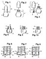
- the packaging and application device 1 shown in FIGS. 1 to 3 comprises a bottle 2, made for example of glass or plastic, and a applicator 3 comprising a rod 4, provided at its lower end with an element application 5 such as for example a brush, and connected at its upper end to a closure cap 6, which has a threaded portion 7 and a ring 8 in part lower.
- the rod 4 is for example a hollow rod inside which the tuft of bristles of the brush is inserted, the apparent length l of the bristles being for example 12 mm or more.
- the rod 4 can be fixed inside the closure cap 6 so that conventionally by means of an insert which may serve to further ensure tight closure of the bottle.
- the threaded portion 7 is intended to be screwed onto the neck 10 of the bottle 2, this neck 10 being provided with a thread 11.
- the ring 8 is initially secured of the threaded portion 7 when the applicator 3 is put in place for the first time on the bottle 2.
- the ring 8 can for example be made, as seen in FIG. integrally by molding plastic material with the threaded portion 7, both being connected by one or more bridges of breakable material 13. It is seen in this figure that the material bridges 13 are set back from the radially outer surface 19 of the ring 8, so as not to harm the aesthetics of the capsule.
- the ring 8 moreover comprises in the example considered at least one first relief 15, for example a bead or teeth protruding on its surface radially inner 16, and the neck 10 of the bottle 2 comprises at its base at least a second relief 18 arranged to allow snapping on the neck of the ring 8 at the end of the screwing initial of the closure cap 6 on the bottle 2.
- At least one anti-rotation relief 20 is made on the radially inner surface 16 of the ring 8, so as to cooperate with at least one complementary relief 21 made on the neck 10.
- the reliefs 20 and 21 are arranged so to allow the relief 20 to cross the relief 21 during the initial screwing of the capsule of closure 6 and the reliefs 20 and 21 comprise for example for this purpose ramps 23 and 24. The latter are inclined so as to assist the relief 20 to cross the relief 21 in the screwing direction of the closure cap, the reliefs 20 and 21 preventing a new crossing in the opposite direction.
- the threaded portion 7 separates from the ring 8, which remains permanently on the neck 10 and the user can benefit from an apparent length of rod 4 sufficient to allow a application in good conditions of the product, on the nails for example.
- the closure cap can be made with a threaded portion 7 and a ring 8 which are connected by material bridges 13 directed substantially radially, as seen in FIG. 7, and no longer substantially axially it is represented in FIG.
- the ring 8 and the threaded portion 7 can still be connected otherwise than by bridges of breakable material before mounting the closure cap 6 on the bottle 2.
- FIG. 8 shows a variant embodiment which the threaded portion 7 and the ring 8 are arranged to cooperate by interlocking, the ring 8 being for example provided with an annular rib 33 adapted to engage in a shoulder housing 24 formed at the lower end of the threaded portion 7.
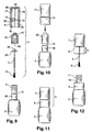
- closure cap comprises an insert 40 and an overcap 41 inside which the insert 40 can be fixed.
- the insert 40 internally comprises a thread 42 intended to allow its screwing on the neck 10 and a housing 43 for fixing on the insert 40 of the end upper 44 of the rod 4.
- the latter comprises a collar 45 intended to bear on the slice of the neck 10 at the end of the screwing of the insert 40, in order to seal the bottle 2.
- Overcap 41 has on its radially inner surface ribs axial means 48 intended to allow clamping of the overcap 41 on the insert 40, the two pieces being then immobile with respect to each other.
- the ring 8 is made in the example considered in one piece with the overcap 41, being connected thereto by material bridges 13 located in the extension of ribs 48.
- the ring 8 has on its inner surface axial ribs 50 located in the extension of the ribs 48, intended to bear on an enlarged portion 56 at the base of the neck 10, with sufficient tightening so that the ring 8 is then immobilized in rotation relative to the bottle 2.
- the insert 40 and the stem 4 can be put in place. to close the bottle, as illustrated in Figure 10, and then the assembly constituted by the over-capsule 41 and the ring 8 can be attached to the insert 40, until the insert 40 bears against the bottom of the top wall of the overcap 41, the ribs 48 applying tightly to the insert 40.
- the bottle 2 provided with the closure cap has been shown in FIG.
- the user unscrews the threaded portion 7 made up of the overcap 41 and of the insert 40, the ring 8 remaining on the neck 10 of the bottle by tightening the ribs 50 on the enlarged part 56, as can be seen in Figure 12. It is understood on examination of this figure that thanks to the fact that the ring 8 remains on the neck 10 of the bottle 2, it is possible to gain in apparent length of rod the equivalent of the height h of the ring 8.
- the application element 5 can be constituted by something other than a brush and, by way of illustration, FIG. 14 shows a flocked application element intended to for example to the application on the lips.
- the bottle 2 can be made by assembling one or more pieces and include in particular a wiper member 60 as illustrated in FIG. this figure that the bottle 2 may comprise a body 61 on which is reported a room 62 defining the neck 10 of the bottle and for supporting the wiper member 60, which can be constituted for example by a foam block split axially to allow the passage of the application element 5.
- the bottle 2 can be filled with a product P intended for example to be applied to the lips.
- the closure cap 6 can be made with various shapes, as can see it in Figures 16 to 18, its outer section being circular or not, especially prismatic.
- FIG. 19 shows an overcap 41 having a substantially square outer cross section.
- This overcap can be realized with internally a cylindrical wall 63 of revolution, intended to allow the fixation of a insert bearing the thread of the closure cap and the stem.
Abstract
Description
La présente invention concerne les dispositifs de conditionnement et d'application d'un produit cosmétique, y compris de soin, et plus particulièrement mais non exclusivement ceux destinés à l'application d'un vernis à ongles.The present invention relates to packaging devices and application of a cosmetic product, including care, and more particularly but not exclusively those intended for the application of a nail polish.
Un dispositif selon le préamble de la revendication 1 est connu
par le document DE-A-10 104 042.A device according to the preamble of
Les flacons de vernis à ongles rencontrés sur le marché présentent diverses contenances, le plus souvent entre 7 et 14 ml. Les applicateurs associés comprennent une tige avec un pinceau à une extrémité et une capsule de fermeture ayant une partie filetée.The nail polish bottles on the market have a variety of contents, most often between 7 and 14 ml. Associated applicators include a stem with a brush at one end and a closure cap having a threaded portion.
Pour les flacons de contenance relativement grande, par exemple 12 ml ou plus, la hauteur du corps du flacon permet d'utiliser une tige relativement longue. Par contre, pour les flacons de plus petite contenance, la hauteur du corps du flacon est moindre et la tige doit être plus courte, sauf à raccourcir la longueur des poils du pinceau et perdre en souplesse et en qualité d'application ou augmenter la longueur du col, ce qui est gênant pour l'esthétique.For bottles with a relatively large capacity, for example 12 ml or Moreover, the height of the body of the bottle makes it possible to use a relatively long rod. By cons, for bottles of smaller capacity, the height of the body of the bottle is lesser and the stem should be shorter, except to shorten the length of the bristles of the brush and lose flexibility and quality of application or increase the length of the cervix, which is embarrassing for the aesthetics.
Or, il est souhaitable d'avoir à la fois des poils relativement longs et une longueur de tige apparente qui n'est pas trop courte afin de faciliter l'application.However, it is desirable to have both relatively long hairs and a apparent stem length that is not too short to facilitate application.
L'invention vise notamment à répondre à ce besoin.The invention aims in particular to meet this need.
Elle y parvient grâce à un dispositif de conditionnement et d'application comportant :
- un flacon comportant un col fileté,
- un applicateur comportant :
- une tige,
- un élément d'application disposé à une première extrémité de la tige,
- une capsule de fermeture supportant la tige à une deuxième extrémité opposée à la première, cette capsule de fermeture comportant une partie filetée agencée pour se visser sur le col,
- a bottle with a threaded neck,
- an applicator comprising:
- a rod,
- an application element disposed at a first end of the rod,
- a closure cap supporting the rod at a second end opposite to the first, this closure cap having a threaded portion arranged to be screwed onto the neck,
Grâce à l'invention, on peut bénéficier d'une longueur apparente tige plus élément d'application relativement importante, sans pour autant nuire à l'esthétique du flacon, grâce à la bague présente à la base du col. En outre, la mise en place de la bague peut s'effectuer d'une manière relativement aisée et économique, après le remplissage du flacon.Thanks to the invention, it is possible to benefit from an apparent length of stem more element of relatively important application, without compromising the aesthetics of the bottle, thanks to the ring at the base of the neck. In addition, the establishment of the ring can be done in a relatively easy and economical way, after the filling of the bottle.
On peut également réaliser la bague et la partie filetée de manière à donner l'impression d'une capsule de fermeture réalisée d'un seul tenant lorsque l'applicateur est en place sur le flacon, ce qui peut être favorable sur le plan esthétique.It is also possible to make the ring and the threaded part so as to give the impression of a closure cap made in one piece when the applicator is in place on the bottle, which may be aesthetically favorable.
L'expression « partie filetée » doit être comprise avec un sens large comme correspondant à la partie de la capsule de fermeture qui porte au moins un filetage, ce dernier pouvant être réalisé le cas échéant sur un insert fixé dans une surcapsule. Dans ce cas, la bague peut être reliée de façon amovible à l'insert ou à la surcapsule.The expression "threaded part" must be understood in a broad sense as corresponding to the part of the closure cap which carries at least one thread, this last can be made if necessary on an insert fixed in an overcap. In this case, the ring can be removably connected to the insert or the overcap.
La bague peut comporter ou non un filetage.The ring may or may not have a thread.
Dans une réalisation particulière, la bague comporte au moins un premier relief permettant sa fixation par encliquetage sur au moins un deuxième relief réalisé sur le col. Ce deuxième relief peut par exemple comporter un bourrelet annulaire et le premier relief comporter un bourrelet annulaire ou des dents formant saillie sur la surface radialement intérieure de la bague.In a particular embodiment, the ring comprises at least one first relief allowing its fastening by snapping on at least one second relief made on the neck. This second relief may for example comprise an annular bead and the first relief have an annular bead or teeth protruding radially on the surface inside the ring.
La bague peut encore comporter au moins un relief agencé pour retenir par friction la bague sur le col. La bague peut notamment comporter des nervures sur sa surface intérieure.The ring may also comprise at least one relief arranged to retain by friction the ring on the collar. The ring may include ribs on its inner surface.
La bague et la partie filetée peuvent être réalisées de manière monolithique ou non.The ring and the threaded portion may be made monolithically or no.
La bague peut avantageusement être réalisée au moins partiellement par moulage de matière plastique avec la partie filetée, notamment avec la surcapsule lorsque la partie filetée comporte un insert et une surcapsule. La bague peut être reliée par des ponts de matière sécables à la partie filetée.The ring may advantageously be made at least partially by molding of plastic material with the threaded part, in particular with the overcap when the threaded portion has an insert and an overcap. The ring can be connected by bridges of breakable material at the threaded part.
La bague peut encore être disposée sur la partie filetée en étant rapportée sur celle-ci, la partie filetée et la bague étant par exemple réalisées dans des moules différents. La bague peut comporter par exemple un relief lui permettant de coopérer par emboítement avec la partie filetée. La bague peut ainsi ne pas être reliée à la partie filetée par des ponts de matière sécables.The ring can still be arranged on the threaded part by being attached to this, the threaded portion and the ring being for example made in different molds. The ring may comprise for example a relief allowing it to cooperate by interlocking with the threaded part. The ring can thus not be connected to the threaded portion by bridges of breakable material.
Lorsque la bague et la partie filetée ne sont pas monolithiques, elles peuvent être assemblées par encliquetage, friction, collage ou soudage par exemple. When the ring and the threaded part are not monolithic, they can be assembled by snapping, friction, bonding or welding for example.
La bague et la partie filetée peuvent encore être reliées l'une à l'autre par d'autres moyens de fixation.The ring and the threaded part can still be connected to each other by other fastening means.
Le col peut comporter au moins un premier relief d'anti-rotation et la bague au moins un deuxième relief d'anti-rotation agencé pour coopérer avec le premier relief de manière à empêcher la bague de tourner par rapport au col lors du dévissage de la capsule de fermeture conduisant à la séparation de la partie filetée et de la bague.The neck may comprise at least a first anti-rotation relief and the ring at least a second anti-rotation relief arranged to cooperate with the first relief of to prevent the ring from rotating relative to the neck when unscrewing the capsule closure leading to the separation of the threaded portion and the ring.
Ce premier relief, réalisé sur le flacon, peut être agencé pour permettre son franchissement par le deuxième relief lors du vissage initial de la capsule de fermeture sur le flacon. Au moins l'un des premier et deuxième reliefs peut comporter une rampe facilitant ce franchissement.This first relief, made on the bottle, can be arranged to allow its crossing by the second relief during initial screwing of the closure cap on vial. At least one of the first and second reliefs may comprise a ramp facilitating this crossing.
L'immobilisation en rotation de la bague sur le col peut encore être obtenue par serrage de la bague sur le col, notamment lorsque la bague comporte des nervures sur sa surface intérieure.The immobilization in rotation of the ring on the neck can still be obtained by tightening of the ring on the neck, especially when the ring has ribs on its inner surface.
Le col peut comporter à sa base une surface cylindrique ou une surface tronconique s'élargissant vers le corps du flacon, sur laquelle peut venir en appui avec un certain serrage la bague.The neck may have at its base a cylindrical surface or a surface frustoconical widening towards the body of the bottle, on which can come in support with a some tightening the ring.
La bague peut être décorée.The ring can be decorated.
Le flacon peut être réalisé avec diverses formes et notamment avec un épaulement à la base du col.The bottle can be made with various shapes and in particular with a shoulder at the base of the collar.
Le flacon peut être réalisé en verre ou en matière plastique, et notamment être dans une matière transparente.The bottle may be made of glass or plastic, and in particular be in a transparent material.
La contenance du flacon peut être inférieure ou égale à 10 ml, notamment inférieure ou égale à 8 ml, comprise par exemple entre environ 7 ml et environ 5 ml.The capacity of the bottle may be less than or equal to 10 ml, in particular less than or equal to 8 ml, for example between about 7 ml and about 5 ml.
La longueur apparente de la tige et de l'élément d'application peut par exemple être supérieure ou égale à 25 mm. Dans le cas où l'élément d'application est un pinceau, la longueur apparente de la partie libre des poils est par exemple supérieure ou égale à 12 mm.The apparent length of the rod and the applicator element may for example be greater than or equal to 25 mm. In the case where the application element is a brush, the apparent length of the free part of the bristles is for example greater than or equal to 12 mm.
Le flacon peut contenir par exemple un produit à appliquer sur les ongles, notamment un vernis à ongles. Le flacon peut encore contenir un produit à appliquer sur le visage, notamment sur les lèvres. Le flacon peut comporter dans ce cas notamment un organe d'essorage. The bottle may contain, for example, a product to be applied to the nails, especially a nail polish. The bottle may still contain a product to be applied on the face, especially on the lips. In this case, the bottle may in particular include a wringing member.
L'élément d'application peut être floqué, notamment pour une application sur la peau ou les lèvres.The application element can be flocked, especially for an application on skin or lips.
La longueur de la tige peut être sensiblement égale à la hauteur du col, la longueur de la tige étant par exemple égale, à 30 % près, à la hauteur du col.The length of the stem may be substantially equal to the height of the neck, the length of the stem being for example equal to 30% near the height of the neck.
La longueur de l'élément d'application peut être sensiblement égale à la hauteur du corps du flacon, sur lequel se raccorde le col ; la longueur de l'élément d'application peut ainsi être égale, par exemple, à 30 % près à la hauteur du corps.The length of the application element may be substantially equal to the height of the body of the bottle, on which connects the neck; the length of the element application can be equal, for example, to 30% near the height of the body.
L'invention a encore pour objet un procédé de fabrication d'un dispositif de conditionnement et d'application comportant les étapes suivantes :
- visser sur un flacon comportant un col fileté un applicateur comportant :
- une tige,
- un élément d'application disposé à une première extrémité de la tige,
- une capsule de fermeture dont la tige est solidaire à une deuxième extrémité, opposée à la première, cette capsule de fermeture comportant une partie filetée agencée pour se visser sur le col, la capsule de fermeture comportant à sa base une bague reliée de façon amovible à la partie filetée, le col et la bague comportant des formes agencées pour coopérer afin de retenir la bague sur le col lorsque la partie filetée est dévissée, au moment de l'utilisation.
- screw on a bottle having a threaded neck an applicator comprising:
- a rod,
- an application element disposed at a first end of the rod,
- a closure cap whose rod is secured to a second end, opposite to the first, this closure cap having a threaded portion arranged to screw on the neck, the closure cap having at its base a ring removably connected to the threaded portion, the neck and the ring having shapes arranged to cooperate to retain the ring on the neck when the threaded portion is unscrewed at the time of use.
Le col et la bague peuvent notamment coopérer par encliquetage ou par friction.The collar and the ring may in particular cooperate by snapping or by friction.
L'invention a encore pour objet un procédé de fabrication d'un dispositif de conditionnement et d'application, comportant les étapes suivantes :
- visser sur un flacon comportant un col fileté un insert fileté duquel l'élément d'application est solidaire,
- rapporter une surcapsule sur l'insert, la surcapsule étant reliée à une bague de façon amovible, la surcapsule et l'insert restant solidaires lorsque l'insert est dévissé, le col et la bague comportant des formes agencées pour coopérer afin de retenir la bague sur le col lorsque l'insert est dévissé.
- screw on a bottle having a threaded neck a threaded insert which the application element is secured to,
- report an overcap on the insert, the overcap being removably connected to a ring, the overcap and the insert remaining integral when the insert is unscrewed, the neck and the ring having shapes arranged to cooperate to retain the ring on the neck when the insert is unscrewed.
L'invention pourra être mieux comprise à la lecture de la description détaillée qui va suivre, d'exemples de mise en oeuvre non limitatifs de l'invention, et à l'examen du dessin annexé, sur lequel :
- la figure 1 représente en élévation de manière schématique un exemple de dispositif de conditionnement et d'application réalisé conformément à l'invention,
- la figure 2 est une vue analogue à la figure 1, représentant le dispositif lors du dévissage initial de la capsule de fermeture,
- la figure 3 est une vue analogue à la figure 1, représentant l'applicateur complètement retiré du flacon,
- la figure 4 représente isolément le flacon, sans la bague ni le reste de la capsule de fermeture,
- la figure 5 est une coupe axiale schématique du flacon de la figure 3, pourvu de la bague,
- la figure 6 représente schématiquement et partiellement, en coupe axiale, la capsule de fermeture du dispositif des figures 1 à 3,
- les figures 7
et 8 sont des coupes axiales schématiques et partielles de variantes de réalisation de la capsule de fermeture, - la figure 9 est une vue éclatée, schématique, d'un autre exemple de mise en oeuvre de l'invention,
- la figure 10 représente le dispositif de la figure 9 après vissage de l'insert sur le col du flacon,
- la figure 11 représente le dispositif de la figure 10 après mise en place de la surcapsule et de la bague,
- la figure 12 représente le dispositif de la figure 11 après retrait de l'applicateur,
- la figure 13 représente isolément et de manière schématique une variante de réalisation du flacon,
- la figure 14 représente un applicateur comportant un élément d'application floqué,
- la figure 15 est une coupe axiale schématique et partielle d'un flacon conforme à une variante de réalisation, ce flacon comportant un organe d'essorage,
- les figures 16 à 18 représentent de manière schématique et partielle, en élévation, des capsules de fermeture conformes à des variantes de mise en oeuvre de l'invention, et
- la figure 19 représente isolément et de manière schématique une surcapsule ayant une section transversale extérieure non circulaire.
- FIG. 1 is a diagrammatic representation of an exemplary packaging and application device produced in accordance with the invention,
- FIG. 2 is a view similar to FIG. 1, showing the device during initial unscrewing of the closure cap,
- FIG. 3 is a view similar to FIG. 1, showing the applicator completely removed from the bottle,
- FIG. 4 represents, in isolation, the bottle, without the ring or the remainder of the closure cap,
- FIG. 5 is a schematic axial section of the bottle of FIG. 3, provided with the ring,
- FIG. 6 diagrammatically and partially, in axial section, the closure cap of the device of FIGS. 1 to 3,
- FIGS. 7 and 8 are schematic and partial axial sections of alternative embodiments of the closure cap,
- FIG. 9 is an exploded schematic view of another embodiment of the invention;
- FIG. 10 represents the device of FIG. 9 after screwing the insert onto the neck of the bottle,
- FIG. 11 represents the device of FIG. 10 after putting in place the overcap and the ring,
- FIG. 12 represents the device of FIG. 11 after removal of the applicator,
- FIG. 13 represents in isolation and schematically an alternative embodiment of the bottle,
- FIG. 14 represents an applicator comprising a flocked application element,
- FIG. 15 is a schematic and partial axial section of a bottle according to an embodiment variant, this bottle comprising a wiper member,
- FIGS. 16 to 18 show diagrammatically and partially, in elevation, closure caps according to alternative embodiments of the invention, and
- FIG. 19 represents, in isolation and schematically, an overcap with an outer non-circular cross section.
Le dispositif de conditionnement et d'application 1 représenté aux figures 1 à 3
comporte un flacon 2, réalisé par exemple en verre ou en matière plastique, et un
applicateur 3 comportant une tige 4, munie à son extrémité inférieure d'un élément
d'application 5 tel que par exemple un pinceau, et raccordée à son extrémité supérieure à
une capsule de fermeture 6, laquelle comporte une partie filetée 7 et une bague 8 en partie
inférieure.The packaging and
La tige 4 est par exemple une tige creuse à l'intérieur de laquelle la touffe de
poils du pinceau est insérée, la longueur apparente l des poils étant par exemple de 12 mm
ou plus.The
La tige 4 peut être fixée à l'intérieur de la capsule de fermeture 6 de façon
conventionnelle au moyen d'un insert qui sert éventuellement à assurer en outre une
fermeture étanche du flacon.The
La partie filetée 7 est destinée à se visser sur le col 10 du flacon 2, ce col 10
étant pourvu d'un filetage 11.The threaded
Conformément à un aspect de l'invention, la bague 8 est initialement solidaire
de la partie filetée 7 lorsque l'applicateur 3 est mis en place pour la première fois sur le
flacon 2.According to one aspect of the invention, the
La bague 8 peut par exemple être réalisée, comme on le voit sur la figure 6,
d'un seul tenant par moulage de matière plastique avec la partie filetée 7, les deux étant
reliées par un ou plusieurs ponts de matière sécables 13. On voit sur cette figure que les
ponts de matière 13 se situent en retrait de la surface radialement extérieure 19 de la bague
8, de façon à ne pas nuire à l'esthétique de la capsule.The
La bague 8 comporte par ailleurs dans l'exemple considéré au moins un
premier relief 15, par exemple un bourrelet ou des dents faisant saillie sur sa surface
radialement intérieure 16, et le col 10 du flacon 2 comporte à sa base au moins un second
relief 18 agencé pour permettre l'encliquetage sur le col de la bague 8 au terme du vissage
initial de la capsule de fermeture 6 sur le flacon 2.The
De façon à permettre lors du dévissage de la capsule de fermeture 6 à la bague
8 de se séparer de la partie filetée 7, au moins un relief d'anti-rotation 20 est réalisé sur la
surface radialement intérieure 16 de la bague 8, de manière à coopérer avec au moins un
relief complémentaire 21 réalisé sur le col 10. Les reliefs 20 et 21 sont agencés de manière
à permettre au relief 20 de franchir le relief 21 lors du vissage initial de la capsule de
fermeture 6 et les reliefs 20 et 21 comportent par exemple à cet effet des rampes
respectives 23 et 24. Ces dernières sont inclinées de façon à aider le relief 20 à franchir le
relief 21 dans le sens du vissage de la capsule de fermeture, les reliefs 20 et 21 empêchant
un nouveau franchissement dans le sens inverse.So as to allow when unscrewing the
Lorsque l'utilisateur dévisse pour la première fois la capsule de fermeture 6, la
partie filetée 7 se sépare de la bague 8, laquelle reste à demeure sur le col 10 et l'utilisateur
peut bénéficier d'une longueur apparente l' de tige 4 suffisante pour permettre une
application dans de bonnes conditions du produit, sur les ongles par exemple.When the user unscrews for the first time the
Bien entendu, l'invention n'est pas limitée à l'exemple de réalisation qui vient d'être décrit. On peut notamment apporter diverses modifications au flacon et à la capsule de fermeture.Of course, the invention is not limited to the embodiment which comes to be described. In particular, it is possible to make various modifications to the bottle and to the capsule closure.
Par exemple, la capsule de fermeture peut être réalisée avec une partie filetée 7
et une bague 8 qui sont reliées par des ponts de matière 13 dirigés sensiblement
radialement, comme on le voit sur la figure 7, et non plus sensiblement axialement comme
on l'a représenté sur la figure 6.For example, the closure cap can be made with a threaded
La bague 8 et la partie filetée 7 peuvent encore être reliées autrement que par
des ponts de matière sécables avant le montage de la capsule de fermeture 6 sur le flacon 2.The
A titre d'exemple, on a représenté à la figure 8 une variante de réalisation dans
laquelle la partie filetée 7 et la bague 8 sont agencées pour coopérer par emboítement, la
bague 8 étant par exemple pourvue d'une nervure annulaire 33 apte à s'engager dans un
logement épaulé 24 réalisé à l'extrémité inférieure de la partie filetée 7.By way of example, FIG. 8 shows a variant embodiment
which the threaded
On va maintenant décrire en référence aux figures 9 à 12 une variante de
réalisation dans laquelle la capsule de fermeture comporte un insert 40 et une surcapsule 41
à l'intérieur de laquelle l'insert 40 peut se fixer.We will now describe with reference to FIGS. 9 to 12 a variant of
embodiment in which the closure cap comprises an
L'insert 40 comporte intérieurement un filetage 42 destiné à permettre son
vissage sur le col 10 et un logement 43 permettant la fixation sur l'insert 40 de l'extrémité
supérieure 44 de la tige 4.The
Cette dernière comporte une collerette 45 destinée à venir en appui sur la
tranche du col 10 au terme du vissage de l'insert 40, afin de fermer de manière étanche le
flacon 2. The latter comprises a
La surcapsule 41 comporte sur sa surface radialement intérieure des nervures
axiales 48 destinées à permettre la fixation par serrage de la surcapsule 41 sur l'insert 40,
les deux pièces étant alors immobiles l'une par rapport à l'autre.
La bague 8 est réalisée dans l'exemple considéré d'un seul tenant avec la
surcapsule 41, étant reliée à celle-ci par des ponts de matière 13 situés dans le
prolongement des nervures 48.The
La bague 8 comporte sur sa surface intérieure des nervures axiales 50 situées
dans le prolongement des nervures 48, destinées à venir en appui sur une portion élargie 56
à la base du col 10, avec un serrage suffisant pour que la bague 8 soit ensuite immobilisée
en rotation relativement au flacon 2.The
Après le remplissage du flacon 2, on peut mettre en place l'insert 40 et la tige 4
de manière à fermer le flacon, comme illustré sur la figure 10, puis l'ensemble constitué
par la surcapsule 41 et la bague 8 peut être rapporté sur l'insert 40, jusqu'à ce que l'insert
40 vienne en appui contre le fond de la paroi de dessus de la surcapsule 41, les nervures 48
venant s'appliquer avec serrage sur l'insert 40.After filling the
Le flacon 2 muni de la capsule de fermeture a été représenté à la figure 11.
Lors de l'utilisation, l'utilisateur dévisse la partie filetée 7 composée de la surcapsule 41 et
de l'insert 40, la bague 8 restant sur le col 10 du flacon par serrage des nervures 50 sur la
partie élargie 56, comme on le voit sur la figure 12. On comprend à l'examen de cette
figure que grâce au fait que la bague 8 reste sur le col 10 du flacon 2, on peut gagner en
longueur apparente de tige l'équivalent de la hauteur h de la bague 8.The
On ne sort pas de la présente invention lorsque le col 10 est réalisé avec, à sa
base, non pas une surface cylindrique de révolution mais une surface tronconique. A titre
d'exemple, on a représenté à la figure 13 le flacon 2 de l'exemple de réalisation des figures
1 à 5 avec à la base du col 10 une partie inférieure tronconique 32 permettant par exemple
d'accroítre le serrage entre la bague 8 et le flacon 2.We do not leave the present invention when the
L'élément d'application 5 peut être constitué par autre chose qu'un pinceau et,
à titre d'illustration, on a représenté à la figure 14 un élément d'application floqué, destiné
par exemple à l'application sur les lèvres.The
Le flacon 2 peut être réalisé par assemblage d'une ou plusieurs pièces et
notamment comporter un organe d'essorage 60 comme illustré à la figure 15. On voit sur
cette figure que le flacon 2 peut comporter un corps 61 sur lequel est rapportée une pièce
62 définissant le col 10 du flacon et permettant de supporter l'organe d'essorage 60, lequel
peut être constitué par exemple par un bloc de mousse fendu axialement afin de permettre
le passage de l'élément d'application 5. Dans cet exemple, le flacon 2 peut être rempli d'un
produit P destiné par exemple à être appliqué sur les lèvres.The
La capsule de fermeture 6 peut être réalisée avec diverses formes, comme on
peut le voir sur les figures 16 à 18, sa section extérieure pouvant être circulaire ou non,
notamment prismatique.The
A titre d'illustration, on a représenté à la figure 19 une surcapsule 41 ayant une
section transversale extérieure sensiblement carrée. Cette surcapsule peut être réalisée avec
intérieurement une paroi 63 cylindrique de révolution, destinée à permettre la fixation d'un
insert portant le filetage de la capsule de fermeture et la tige.By way of illustration, FIG. 19 shows an
Dans toute la description, y compris les revendications, l'expression « comportant un » doit être comprise comme étant synonyme de « comportant au moins un », sauf si le contraire est spécifié.Throughout the description, including the claims, the expression "Comprising one" must be understood as being synonymous with "comprising at least a ", unless the opposite is specified.
Claims (28)
- A packaging and applicator device comprising:the device being characterized by the fact that the closure cap includes a ring (8) releasably connected to the threaded portion (7) and arranged to be capable of remaining secured to the neck during removal of the applicator.a flask presenting a threaded neck (10);an applicator comprising:a stem (4);an applicator element (5) disposed at a first end of the stem;a closure cap (6) supporting the stem at a second end opposite from the first, said closure cap including a threaded portion (7) arranged to screw onto the neck;
- A device according to claim 1, characterized by the fact that the threaded portion (7) comprises an insert (40) and an outer cap (41).
- A device according to claim 2, characterized by the fact that the ring (8) and the outer cap (41) are made integrally by molding a plastics material, the ring and the outer cap being connected together by at least one breakable bridge of material (13).
- A device according to any one of claims 1 to 3, characterized by the fact that the ring (8) presents at least one first portion in relief (15) enabling it to be snap-fastened on at least one second portion in relief (18) made on the neck.
- A device according to the preceding claim, characterized by the fact that the second portion in relief (18) comprises an annular bead and the first portion in relief (15) comprises an annular bead or teeth projecting from the radially inner surface (16) of the ring (8).
- A device according to any one of the preceding claims, characterized by the fact that the ring (8) is made at least in part together with the threaded portion (7) by molding plastics material.
- A device according to the preceding claim, characterized by the fact that the ring (8) is connected to the threaded portion (7) by breakable bridges of material (13).
- A device according to claim 1 or 2, characterized by the fact that the ring is fitted on the threaded portion.
- A device according to the preceding claim, characterized by the fact that the ring presents a portion in relief (33) enabling it to co-operate by mutual engagement with the threaded portion (7).
- A device according to any one of the preceding claims, characterized by the fact that the neck includes at least one first anti-rotation portion in relief (21) and the ring includes at least one second anti-rotation portion in relief (20) arranged to co-operate with the first portion in relief so as to prevent the ring from turning relative to the neck during unscrewing of the closure cap leading to separation of the threaded portion (7) from the ring (8).
- A device according to the preceding claim, characterized by the fact that the first anti-rotation portion in relief (21) is arranged to enable the second anti-rotation portion in relief (20) to go past it on initial screw fastening of the closure cap on the flask.
- A device according to the preceding claim, characterized by the fact that at least one of the first and second portions in relief includes a ramp (23; 24) for making it easier for them to go past each other.
- A device according to any one of the preceding claims, characterized by the fact that the neck comprises a cylindrical surface at its base.
- A device according to any one of claims 1 to 12, characterized by the fact that the neck comprises a frustoconical surface (32) at its base, said surface flaring towards the body of the flask.
- A device according to any one of the preceding claims, characterized by the fact that the flask is made with a shoulder at the base of the neck.
- A device according to any one of the preceding claims, characterized by the fact that the flask is made with a surface for coming into contact with the ring and preventing it from moving.
- A device according to any one of the preceding claims, characterized by the fact that the ring includes splines (50) on its inner surface.
- A device according to any one of the preceding claims, characterized by the fact that the flask is made of glass.
- A device according to any one of claims 1 to 13, characterized by the fact that the flask is made of plastics material.
- A device according to any one of the preceding claims, characterized by the fact that the capacity of the flask is less than or equal to 10 ml, in particular less than or equal to 8 ml, better lying in the range about 7 ml to about 5 ml.
- A device according to any one of the preceding claims, characterized by the fact that the stem (4) is visible when the applicator is withdrawn from the flask, and the closure cap is observed in a direction perpendicular to its axis.
- A device according to the preceding claim, characterized by the fact that the visible length (ℓ+ℓ') of the stem plus the applicator element is greater than or equal to 25 mm.
- A device according to any one of the preceding claims, characterized by the fact that the applicator element is a brush, and by the fact that the visible length (ℓ) of the free portion of the bristles of the brush is greater than or equal to 12 mm.
- A device according to any one of the preceding claims, characterized by the fact that the flask contains a substance for application to the nails, in particular a nail varnish.
- A device according to any one of the preceding claims, characterized by the fact that the length of the stem is equal to the height of the neck to within 30%.
- A device according to any one of the preceding claims, characterized by the fact that the length of the applicator element is equal to the height of the flask body, to within 30%.
- A method of manufacturing a packaging and applicator device, the method comprising the following steps:screwing onto a flask (2) having a threaded neck (10) an applicator (3) comprising:a stem (4);an applicator element (5) disposed at a first end of the stem;a closure cap (6) to which the stem (4) is secured at a second end opposite from the first, said closure cap presenting a threaded portion (7) arranged to be screwed onto the neck, the closure cap including at its base a ring (8) releasably connected to the threaded portion (7), the neck and the ring presenting shapes arranged to co-operate so as to retain the ring on the neck when the threaded portion is unscrewed.
- A method of manufacturing a packaging and applicator device, the method comprising the following steps:screwing onto a flask presenting a threaded neck (10) a threaded insert (40) to which an applicator is secured, the applicator comprising a stem (4) and an applicator element (5) disposed at a first end of the stem;fitting an outer cap (41) on the insert, the outer cap being connected releasably to a ring (8), the outer cap and the ring remaining secured to each other when the insert is unscrewed, the neck and the ring presenting shapes arranged to co-operate so as to retain the ring on the neck when the insert is unscrewed.
Applications Claiming Priority (2)
| Application Number | Priority Date | Filing Date | Title |
|---|---|---|---|
| FR0301513 | 2003-02-07 | ||
| FR0301513A FR2850844B1 (en) | 2003-02-07 | 2003-02-07 | PACKAGING AND APPLICATION DEVICE |
Publications (2)
| Publication Number | Publication Date |
|---|---|
| EP1444917A1 EP1444917A1 (en) | 2004-08-11 |
| EP1444917B1 true EP1444917B1 (en) | 2005-04-13 |
Family
ID=32606026
Family Applications (1)
| Application Number | Title | Priority Date | Filing Date |
|---|---|---|---|
| EP04290289A Expired - Lifetime EP1444917B1 (en) | 2003-02-07 | 2004-02-04 | Device for storing and applying a product |
Country Status (7)
| Country | Link |
|---|---|
| EP (1) | EP1444917B1 (en) |
| JP (1) | JP4235571B2 (en) |
| CN (1) | CN1267037C (en) |
| AT (1) | ATE292910T1 (en) |
| DE (1) | DE602004000003T2 (en) |
| ES (1) | ES2240956T3 (en) |
| FR (1) | FR2850844B1 (en) |
Families Citing this family (6)
| Publication number | Priority date | Publication date | Assignee | Title |
|---|---|---|---|---|
| CN105523260A (en) * | 2016-02-05 | 2016-04-27 | 广州百伦贸易有限公司 | Container and nail polish bottle |
| JP6039138B1 (en) * | 2016-03-15 | 2016-12-07 | 株式会社エイエムジー | Tube type cosmetic container |
| FR3054437B1 (en) * | 2016-07-28 | 2018-09-07 | Lvmh Recherche | COSMETIC PRODUCT FOR LIQUIDS IN THE FORM OF A WATER-IN-OIL EMULSION AND METHOD OF MAKE-UP |
| EP3558050A4 (en) * | 2016-12-20 | 2019-12-25 | ELC Management LLC | Fresh cosmetic composition delivery system |
| KR101926084B1 (en) * | 2018-05-29 | 2018-12-07 | 도영에프엔비 주식회사 | A pouch type cosmetic case |
| IT202000018706A1 (en) | 2020-07-31 | 2022-01-31 | Baralan Int S P A | CONTAINER FOR A PRODUCT IN THE FORM OF LIQUID OR GEL, IN PARTICULAR FOR A COSMETIC PRODUCT. |
Family Cites Families (3)
| Publication number | Priority date | Publication date | Assignee | Title |
|---|---|---|---|---|
| DE19642610A1 (en) * | 1996-08-30 | 1998-03-05 | Elvira Ahrens | Small bottle for sticky fluid e.g. cosmetics, adhesive |
| FR2771907B1 (en) * | 1997-12-10 | 2000-02-18 | Oreal | PACKAGING AND APPLICATION ASSEMBLY OF A PRODUCT, ESPECIALLY COSMETIC |
| DE10104042A1 (en) * | 2001-01-29 | 2002-08-01 | Db Design Gmbh | Cosmetic system, e.g. for mascara, comprises bottle and brush for applying cosmetic, handle fitting on to this which can be pushed down to seal bottle in transport position |
-
2003
- 2003-02-07 FR FR0301513A patent/FR2850844B1/en not_active Expired - Fee Related
-
2004
- 2004-02-04 EP EP04290289A patent/EP1444917B1/en not_active Expired - Lifetime
- 2004-02-04 AT AT04290289T patent/ATE292910T1/en not_active IP Right Cessation
- 2004-02-04 DE DE602004000003T patent/DE602004000003T2/en not_active Expired - Lifetime
- 2004-02-04 ES ES04290289T patent/ES2240956T3/en not_active Expired - Lifetime
- 2004-02-06 CN CN200410003824.0A patent/CN1267037C/en not_active Expired - Fee Related
- 2004-02-09 JP JP2004031522A patent/JP4235571B2/en not_active Expired - Fee Related
Also Published As
| Publication number | Publication date |
|---|---|
| DE602004000003D1 (en) | 2005-05-19 |
| JP2004237111A (en) | 2004-08-26 |
| JP4235571B2 (en) | 2009-03-11 |
| CN1518923A (en) | 2004-08-11 |
| ATE292910T1 (en) | 2005-04-15 |
| EP1444917A1 (en) | 2004-08-11 |
| ES2240956T3 (en) | 2005-10-16 |
| CN1267037C (en) | 2006-08-02 |
| FR2850844A1 (en) | 2004-08-13 |
| FR2850844B1 (en) | 2005-04-08 |
| DE602004000003T2 (en) | 2006-04-13 |
Similar Documents
| Publication | Publication Date | Title |
|---|---|---|
| EP1561394B1 (en) | Device for storing and applying a product comprising a wiping element | |
| EP0829211B1 (en) | Device for storing and applying a liquid or semi-liquid product | |
| CA2389875C (en) | Easy-assembly wiper | |
| EP1652449A2 (en) | Make-up kit for keratinous fibres | |
| FR2884501A1 (en) | Cosmetic product e.g. mascara, packaging and applying device for e.g. makeup of skin, has component including pin with rounded or beveled free end and engaged in slit of another component, and applicator detachably fixed on latter component | |
| EP1935279A1 (en) | Applicator for applying a cosmetic product to keratinous materials | |
| EP1614367B1 (en) | Device for storing and applying a product | |
| EP0859563B1 (en) | Applicator-holder | |
| FR3014656A1 (en) | APPLICATOR OF A COSMETIC, MAKE-UP OR CARE PRODUCT, ON LASHES AND / OR EYEBROWS | |
| FR2779041A1 (en) | DEVICE FOR PACKAGING AND APPLYING A COMPOSITION TO KERATINIC FIBERS | |
| EP3603817B1 (en) | Easy mounting and removal of a pump relative to the container | |
| FR3014654A1 (en) | APPLICATOR FOR APPLYING A COSMETIC OR CARE PRODUCT TO LACQUERS OR EYEBROWS | |
| EP1444917B1 (en) | Device for storing and applying a product | |
| FR2544970A1 (en) | MAKE-UP POWDER BOX AND APPLICATOR BRUSH | |
| EP3248500A1 (en) | Bottle for a cosmetic product, and applicator assembly comprising a bottle of this kind and an applicator for said cosmetic product | |
| FR3016274A1 (en) | SPINNING DEVICE WITH VARIABLE GEOMETRY WIPING LIP | |
| FR2577526A1 (en) | CAP FOR BOTTLES | |
| EP3285611B1 (en) | Container, in particular a vial intended for holding a cosmetic product | |
| EP1579784A1 (en) | Device for storing and applying a product, in particular a cosmetic product | |
| FR2890943A1 (en) | Capsule for sealing wine bottles has peripheral line of weakness which allows upper section (to be removed while lower section remains held in place around neck of the bottle by inner flexible rib | |
| FR2908746A1 (en) | Cap i.e. snap cap, for e.g. glass bottle neck, has skirt with peripheral portion in which front bridge piece is located, where thickness of front bridge piece is smaller than thickness of bridge piece located outside peripheral portion | |
| FR3051642A1 (en) | ARTICULATED COSMETIC PRODUCT APPLICATOR AND ASSOCIATED PACKAGING AND APPLICATION ASSEMBLY | |
| FR2868047A1 (en) | Dispensing cap for container of fluid, especially cosmetic, product has base with surface shaped to engage with container and nozzle with outlet covered by break-off tip | |
| EP3989771B1 (en) | Wiper for a liquid or pasty product applicator | |
| FR3058619B1 (en) | LIQUID COSMETIC PRODUCT APPLICATOR |
Legal Events
| Date | Code | Title | Description |
|---|---|---|---|
| PUAI | Public reference made under article 153(3) epc to a published international application that has entered the european phase |
Free format text: ORIGINAL CODE: 0009012 |
|
| 17P | Request for examination filed |
Effective date: 20040209 |
|
| AK | Designated contracting states |
Kind code of ref document: A1 Designated state(s): AT BE BG CH CY CZ DE DK EE ES FI FR GB GR HU IE IT LI LU MC NL PT RO SE SI SK TR |
|
| AX | Request for extension of the european patent |
Extension state: AL LT LV MK |
|
| GRAP | Despatch of communication of intention to grant a patent |
Free format text: ORIGINAL CODE: EPIDOSNIGR1 |
|
| GRAS | Grant fee paid |
Free format text: ORIGINAL CODE: EPIDOSNIGR3 |
|
| GRAA | (expected) grant |
Free format text: ORIGINAL CODE: 0009210 |
|
| AK | Designated contracting states |
Kind code of ref document: B1 Designated state(s): AT BE BG CH CY CZ DE DK EE ES FI FR GB GR HU IE IT LI LU MC NL PT RO SE SI SK TR |
|
| PG25 | Lapsed in a contracting state [announced via postgrant information from national office to epo] |
Ref country code: NL Free format text: LAPSE BECAUSE OF FAILURE TO SUBMIT A TRANSLATION OF THE DESCRIPTION OR TO PAY THE FEE WITHIN THE PRESCRIBED TIME-LIMIT Effective date: 20050413 Ref country code: RO Free format text: LAPSE BECAUSE OF FAILURE TO SUBMIT A TRANSLATION OF THE DESCRIPTION OR TO PAY THE FEE WITHIN THE PRESCRIBED TIME-LIMIT Effective date: 20050413 Ref country code: FI Free format text: LAPSE BECAUSE OF FAILURE TO SUBMIT A TRANSLATION OF THE DESCRIPTION OR TO PAY THE FEE WITHIN THE PRESCRIBED TIME-LIMIT Effective date: 20050413 Ref country code: CZ Free format text: LAPSE BECAUSE OF FAILURE TO SUBMIT A TRANSLATION OF THE DESCRIPTION OR TO PAY THE FEE WITHIN THE PRESCRIBED TIME-LIMIT Effective date: 20050413 Ref country code: SI Free format text: LAPSE BECAUSE OF FAILURE TO SUBMIT A TRANSLATION OF THE DESCRIPTION OR TO PAY THE FEE WITHIN THE PRESCRIBED TIME-LIMIT Effective date: 20050413 Ref country code: AT Free format text: LAPSE BECAUSE OF FAILURE TO SUBMIT A TRANSLATION OF THE DESCRIPTION OR TO PAY THE FEE WITHIN THE PRESCRIBED TIME-LIMIT Effective date: 20050413 Ref country code: SK Free format text: LAPSE BECAUSE OF FAILURE TO SUBMIT A TRANSLATION OF THE DESCRIPTION OR TO PAY THE FEE WITHIN THE PRESCRIBED TIME-LIMIT Effective date: 20050413 Ref country code: IE Free format text: LAPSE BECAUSE OF FAILURE TO SUBMIT A TRANSLATION OF THE DESCRIPTION OR TO PAY THE FEE WITHIN THE PRESCRIBED TIME-LIMIT Effective date: 20050413 |
|
| REG | Reference to a national code |
Ref country code: GB Ref legal event code: FG4D Free format text: NOT ENGLISH |
|
| REG | Reference to a national code |
Ref country code: CH Ref legal event code: EP |
|
| AKX | Designation fees paid |
Designated state(s): AT BE BG CH CY CZ DE DK EE ES FI FR GB GR HU IE IT LI LU MC NL PT RO SE SI SK TR |
|
| REG | Reference to a national code |
Ref country code: IE Ref legal event code: FG4D Free format text: LANGUAGE OF EP DOCUMENT: FRENCH |
|
| REF | Corresponds to: |
Ref document number: 602004000003 Country of ref document: DE Date of ref document: 20050519 Kind code of ref document: P |
|
| GBT | Gb: translation of ep patent filed (gb section 77(6)(a)/1977) |
Effective date: 20050609 |
|
| PG25 | Lapsed in a contracting state [announced via postgrant information from national office to epo] |
Ref country code: SE Free format text: LAPSE BECAUSE OF FAILURE TO SUBMIT A TRANSLATION OF THE DESCRIPTION OR TO PAY THE FEE WITHIN THE PRESCRIBED TIME-LIMIT Effective date: 20050713 Ref country code: DK Free format text: LAPSE BECAUSE OF FAILURE TO SUBMIT A TRANSLATION OF THE DESCRIPTION OR TO PAY THE FEE WITHIN THE PRESCRIBED TIME-LIMIT Effective date: 20050713 Ref country code: GR Free format text: LAPSE BECAUSE OF FAILURE TO SUBMIT A TRANSLATION OF THE DESCRIPTION OR TO PAY THE FEE WITHIN THE PRESCRIBED TIME-LIMIT Effective date: 20050713 Ref country code: BG Free format text: LAPSE BECAUSE OF FAILURE TO SUBMIT A TRANSLATION OF THE DESCRIPTION OR TO PAY THE FEE WITHIN THE PRESCRIBED TIME-LIMIT Effective date: 20050713 |
|
| PG25 | Lapsed in a contracting state [announced via postgrant information from national office to epo] |
Ref country code: HU Free format text: LAPSE BECAUSE OF FAILURE TO SUBMIT A TRANSLATION OF THE DESCRIPTION OR TO PAY THE FEE WITHIN THE PRESCRIBED TIME-LIMIT Effective date: 20050714 |
|
| PG25 | Lapsed in a contracting state [announced via postgrant information from national office to epo] |
Ref country code: PT Free format text: LAPSE BECAUSE OF FAILURE TO SUBMIT A TRANSLATION OF THE DESCRIPTION OR TO PAY THE FEE WITHIN THE PRESCRIBED TIME-LIMIT Effective date: 20050913 |
|
| NLV1 | Nl: lapsed or annulled due to failure to fulfill the requirements of art. 29p and 29m of the patents act | ||
| REG | Reference to a national code |
Ref country code: ES Ref legal event code: FG2A Ref document number: 2240956 Country of ref document: ES Kind code of ref document: T3 |
|
| REG | Reference to a national code |
Ref country code: IE Ref legal event code: FD4D |
|
| PLBE | No opposition filed within time limit |
Free format text: ORIGINAL CODE: 0009261 |
|
| STAA | Information on the status of an ep patent application or granted ep patent |
Free format text: STATUS: NO OPPOSITION FILED WITHIN TIME LIMIT |
|
| PG25 | Lapsed in a contracting state [announced via postgrant information from national office to epo] |
Ref country code: BE Free format text: LAPSE BECAUSE OF NON-PAYMENT OF DUE FEES Effective date: 20060228 Ref country code: MC Free format text: LAPSE BECAUSE OF NON-PAYMENT OF DUE FEES Effective date: 20060228 Ref country code: LU Free format text: LAPSE BECAUSE OF NON-PAYMENT OF DUE FEES Effective date: 20060228 |
|
| 26N | No opposition filed |
Effective date: 20060116 |
|
| BERE | Be: lapsed |
Owner name: L'OREAL Effective date: 20060228 |
|
| PG25 | Lapsed in a contracting state [announced via postgrant information from national office to epo] |
Ref country code: EE Free format text: LAPSE BECAUSE OF FAILURE TO SUBMIT A TRANSLATION OF THE DESCRIPTION OR TO PAY THE FEE WITHIN THE PRESCRIBED TIME-LIMIT Effective date: 20050413 |
|
| PG25 | Lapsed in a contracting state [announced via postgrant information from national office to epo] |
Ref country code: TR Free format text: LAPSE BECAUSE OF FAILURE TO SUBMIT A TRANSLATION OF THE DESCRIPTION OR TO PAY THE FEE WITHIN THE PRESCRIBED TIME-LIMIT Effective date: 20050413 |
|
| REG | Reference to a national code |
Ref country code: CH Ref legal event code: PL |
|
| PG25 | Lapsed in a contracting state [announced via postgrant information from national office to epo] |
Ref country code: CH Free format text: LAPSE BECAUSE OF NON-PAYMENT OF DUE FEES Effective date: 20080229 Ref country code: LI Free format text: LAPSE BECAUSE OF NON-PAYMENT OF DUE FEES Effective date: 20080229 |
|
| PG25 | Lapsed in a contracting state [announced via postgrant information from national office to epo] |
Ref country code: CY Free format text: LAPSE BECAUSE OF FAILURE TO SUBMIT A TRANSLATION OF THE DESCRIPTION OR TO PAY THE FEE WITHIN THE PRESCRIBED TIME-LIMIT Effective date: 20050413 |
|
| PGFP | Annual fee paid to national office [announced via postgrant information from national office to epo] |
Ref country code: FR Payment date: 20120221 Year of fee payment: 9 |
|
| PGFP | Annual fee paid to national office [announced via postgrant information from national office to epo] |
Ref country code: DE Payment date: 20120131 Year of fee payment: 9 |
|
| PGFP | Annual fee paid to national office [announced via postgrant information from national office to epo] |
Ref country code: GB Payment date: 20120201 Year of fee payment: 9 Ref country code: IT Payment date: 20120215 Year of fee payment: 9 |
|
| PGFP | Annual fee paid to national office [announced via postgrant information from national office to epo] |
Ref country code: ES Payment date: 20120307 Year of fee payment: 9 |
|
| GBPC | Gb: european patent ceased through non-payment of renewal fee |
Effective date: 20130204 |
|
| REG | Reference to a national code |
Ref country code: FR Ref legal event code: ST Effective date: 20131031 |
|
| REG | Reference to a national code |
Ref country code: DE Ref legal event code: R119 Ref document number: 602004000003 Country of ref document: DE Effective date: 20130903 |
|
| PG25 | Lapsed in a contracting state [announced via postgrant information from national office to epo] |
Ref country code: IT Free format text: LAPSE BECAUSE OF NON-PAYMENT OF DUE FEES Effective date: 20130204 |
|
| PG25 | Lapsed in a contracting state [announced via postgrant information from national office to epo] |
Ref country code: DE Free format text: LAPSE BECAUSE OF NON-PAYMENT OF DUE FEES Effective date: 20130903 Ref country code: FR Free format text: LAPSE BECAUSE OF NON-PAYMENT OF DUE FEES Effective date: 20130228 Ref country code: GB Free format text: LAPSE BECAUSE OF NON-PAYMENT OF DUE FEES Effective date: 20130204 |
|
| REG | Reference to a national code |
Ref country code: ES Ref legal event code: FD2A Effective date: 20140612 |
|
| PG25 | Lapsed in a contracting state [announced via postgrant information from national office to epo] |
Ref country code: ES Free format text: LAPSE BECAUSE OF NON-PAYMENT OF DUE FEES Effective date: 20130205 |