EP1935279A1 - Applicator for applying a cosmetic product to keratinous materials - Google Patents
Applicator for applying a cosmetic product to keratinous materials Download PDFInfo
- Publication number
- EP1935279A1 EP1935279A1 EP07122332A EP07122332A EP1935279A1 EP 1935279 A1 EP1935279 A1 EP 1935279A1 EP 07122332 A EP07122332 A EP 07122332A EP 07122332 A EP07122332 A EP 07122332A EP 1935279 A1 EP1935279 A1 EP 1935279A1
- Authority
- EP
- European Patent Office
- Prior art keywords
- core
- applicator according
- envelope
- rod
- applicator
- Prior art date
- Legal status (The legal status is an assumption and is not a legal conclusion. Google has not performed a legal analysis and makes no representation as to the accuracy of the status listed.)
- Granted
Links
- 239000000463 material Substances 0.000 title claims abstract description 24
- 239000002537 cosmetic Substances 0.000 title claims description 5
- 102000011782 Keratins Human genes 0.000 claims abstract description 6
- 108010076876 Keratins Proteins 0.000 claims abstract description 6
- 238000004519 manufacturing process Methods 0.000 claims abstract description 4
- 238000000034 method Methods 0.000 claims abstract description 3
- 238000002788 crimping Methods 0.000 claims description 9
- VGGSQFUCUMXWEO-UHFFFAOYSA-N Ethene Chemical compound C=C VGGSQFUCUMXWEO-UHFFFAOYSA-N 0.000 claims description 6
- 229920001684 low density polyethylene Polymers 0.000 claims description 6
- 239000004702 low-density polyethylene Substances 0.000 claims description 6
- 229920000728 polyester Polymers 0.000 claims description 6
- 239000004814 polyurethane Substances 0.000 claims description 6
- 239000011248 coating agent Substances 0.000 claims description 5
- 238000000576 coating method Methods 0.000 claims description 5
- 229920002943 EPDM rubber Polymers 0.000 claims description 4
- 239000004698 Polyethylene Substances 0.000 claims description 4
- 239000000835 fiber Substances 0.000 claims description 4
- 239000002184 metal Substances 0.000 claims description 4
- 238000000465 moulding Methods 0.000 claims description 4
- 150000002825 nitriles Chemical class 0.000 claims description 4
- 238000004806 packaging method and process Methods 0.000 claims description 4
- 229920001296 polysiloxane Polymers 0.000 claims description 4
- 229920000346 polystyrene-polyisoprene block-polystyrene Polymers 0.000 claims description 4
- 229920001935 styrene-ethylene-butadiene-styrene Polymers 0.000 claims description 4
- 229920002725 thermoplastic elastomer Polymers 0.000 claims description 4
- -1 PDM Polymers 0.000 claims description 3
- 229920002614 Polyether block amide Polymers 0.000 claims description 3
- 238000004026 adhesive bonding Methods 0.000 claims description 3
- 125000000484 butyl group Chemical group [H]C([*])([H])C([H])([H])C([H])([H])C([H])([H])[H] 0.000 claims description 3
- 229920001971 elastomer Polymers 0.000 claims description 3
- 239000000806 elastomer Substances 0.000 claims description 3
- 229920001903 high density polyethylene Polymers 0.000 claims description 3
- 239000004700 high-density polyethylene Substances 0.000 claims description 3
- 238000003780 insertion Methods 0.000 claims description 3
- 230000037431 insertion Effects 0.000 claims description 3
- 239000004816 latex Substances 0.000 claims description 3
- 229920000126 latex Polymers 0.000 claims description 3
- 239000000203 mixture Substances 0.000 claims description 3
- 229920001200 poly(ethylene-vinyl acetate) Polymers 0.000 claims description 3
- 229920002635 polyurethane Polymers 0.000 claims description 3
- 229920000915 polyvinyl chloride Polymers 0.000 claims description 3
- 239000004800 polyvinyl chloride Substances 0.000 claims description 3
- 229920000468 styrene butadiene styrene block copolymer Polymers 0.000 claims description 3
- 229920001169 thermoplastic Polymers 0.000 claims description 3
- 239000012815 thermoplastic material Substances 0.000 claims description 3
- 239000004416 thermosoftening plastic Substances 0.000 claims description 3
- 210000000720 eyelash Anatomy 0.000 description 7
- 210000004209 hair Anatomy 0.000 description 6
- 230000000717 retained effect Effects 0.000 description 5
- 239000007779 soft material Substances 0.000 description 3
- 210000004709 eyebrow Anatomy 0.000 description 2
- 239000006260 foam Substances 0.000 description 2
- 239000004033 plastic Substances 0.000 description 2
- 229920003023 plastic Polymers 0.000 description 2
- 239000012781 shape memory material Substances 0.000 description 2
- 239000003086 colorant Substances 0.000 description 1
- 210000000744 eyelid Anatomy 0.000 description 1
- 230000006870 function Effects 0.000 description 1
- 238000000227 grinding Methods 0.000 description 1
- 238000002347 injection Methods 0.000 description 1
- 239000007924 injection Substances 0.000 description 1
- 238000002955 isolation Methods 0.000 description 1
- 229920003031 santoprene Polymers 0.000 description 1
- 238000007789 sealing Methods 0.000 description 1
- 239000007787 solid Substances 0.000 description 1
- 229910001220 stainless steel Inorganic materials 0.000 description 1
- 239000010935 stainless steel Substances 0.000 description 1
- 238000003860 storage Methods 0.000 description 1
- 229920006346 thermoplastic polyester elastomer Polymers 0.000 description 1
- 210000000707 wrist Anatomy 0.000 description 1
Images


Classifications
-
- A—HUMAN NECESSITIES
- A45—HAND OR TRAVELLING ARTICLES
- A45D—HAIRDRESSING OR SHAVING EQUIPMENT; EQUIPMENT FOR COSMETICS OR COSMETIC TREATMENTS, e.g. FOR MANICURING OR PEDICURING
- A45D40/00—Casings or accessories specially adapted for storing or handling solid or pasty toiletry or cosmetic substances, e.g. shaving soaps or lipsticks
- A45D40/26—Appliances specially adapted for applying pasty paint, e.g. using roller, using a ball
- A45D40/262—Appliances specially adapted for applying pasty paint, e.g. using roller, using a ball using a brush or the like
- A45D40/265—Appliances specially adapted for applying pasty paint, e.g. using roller, using a ball using a brush or the like connected to the cap of the container
-
- A—HUMAN NECESSITIES
- A46—BRUSHWARE
- A46B—BRUSHES
- A46B9/00—Arrangements of the bristles in the brush body
- A46B9/02—Position or arrangement of bristles in relation to surface of the brush body, e.g. inclined, in rows, in groups
- A46B9/021—Position or arrangement of bristles in relation to surface of the brush body, e.g. inclined, in rows, in groups arranged like in cosmetics brushes, e.g. mascara, nail polish, eye shadow
-
- A—HUMAN NECESSITIES
- A45—HAND OR TRAVELLING ARTICLES
- A45D—HAIRDRESSING OR SHAVING EQUIPMENT; EQUIPMENT FOR COSMETICS OR COSMETIC TREATMENTS, e.g. FOR MANICURING OR PEDICURING
- A45D40/00—Casings or accessories specially adapted for storing or handling solid or pasty toiletry or cosmetic substances, e.g. shaving soaps or lipsticks
- A45D40/26—Appliances specially adapted for applying pasty paint, e.g. using roller, using a ball
- A45D40/262—Appliances specially adapted for applying pasty paint, e.g. using roller, using a ball using a brush or the like
-
- A—HUMAN NECESSITIES
- A46—BRUSHWARE
- A46B—BRUSHES
- A46B2200/00—Brushes characterized by their functions, uses or applications
- A46B2200/10—For human or animal care
- A46B2200/1046—Brush used for applying cosmetics
- A46B2200/1053—Cosmetics applicator specifically for mascara
-
- A—HUMAN NECESSITIES
- A46—BRUSHWARE
- A46B—BRUSHES
- A46B2200/00—Brushes characterized by their functions, uses or applications
- A46B2200/10—For human or animal care
- A46B2200/1046—Brush used for applying cosmetics
- A46B2200/1053—Cosmetics applicator specifically for mascara
- A46B2200/106—Cosmetics applicator specifically for mascara including comb like element
Definitions
- the present invention relates to applicators for applying a product to keratin materials, and in particular to a cosmetic, makeup or care product, for example a mascara.
- EP 1 351 592 and EP1 384 417 brushes comprising a rigid body on which is molded an application surface of softer material provided with application elements in the form of pins.
- the body has reliefs allowing the softer part to be retained on the rigid body.
- the application elements obtained are flexible since they are made of soft material. However, the application elements being retained at their base on a rigid part, they are strongly constrained when they pass especially through a wiper or when they applied on the eyelashes. If the material used is very soft, the application elements may be deformed during their passage through the wiper. In addition, the application elements going to bed while passing through the wiper, they are strongly dewatered so that the product load remaining on the wiped application elements is affected.
- the document FR2506581 discloses a mascara brush having a tubular shaft and a central shaft extending through the shaft and slidable therein to vary the length of the applicator portion of the brush.
- the rod projects beyond the handle at an application end so as to receive an elastomeric sleeve for applying the product.
- the sleeve is retained at the distal end of the stem by a portion of the rivet head-shaped rod.
- a bellows for applying the product is snapped to the end of the handle. When the rod is slid in the handle, the sleeve or the bellows is deformed so as to vary the application length.
- the document EP1475013 discloses a mascara brush comprising a rod at the end of which is fixed a twisted core carrying bristles on a portion of its circumference, a sleeve having teeth being fitted around the core empoilée so that the teeth s 'extend in the portion of the circumference that has no hair.
- the invention aims to solve at least one of these needs.
- At least a portion of the envelope application area is free with respect to the core means that this portion is not attached or attached to the core.
- a game even very small, can separate this part of the soul's envelope. This allows this part of the envelope to move, even substantially, relative to the soul when it is applied on its outer surface, especially manually. It can for example be stretched or turn around the soul.
- the product is applied to keratin materials or to the passage through a wiper, if the outer surface of the envelope is stretched in one direction, its base not being fixed to the core may also substantially stretch in the same direction so that the outer surface is not too deformed.
- Such a configuration allows to use a very soft material, very flexible, to achieve the envelope without the risk that it is altered when it is mechanically stressed.
- An applicator is thus obtained which allows a very great softness to the application.
- these application elements have a very high flexibility.
- the envelope is sandwiched between the rod and the core makes it possible to immobilize the envelope correctly. This is particularly advantageous when the envelope is made of flexible material, soft, it is then difficult to immobilize.
- the attachment zone of the outer casing may for example be fixed to the rod by crimping, hot or cold.
- the core can also be attached to the end of the stem by crimping, especially at the same level as the envelope and during the same crimping operation.
- the applicator can thus easily be produced industrially.
- the envelope may be closed at its end opposite to the attachment zone so as to completely surround the core which is not accessible from the outside.
- the rod may comprise a main portion and an intermediate portion on which is fixed the applicator member, the intermediate portion being fixed to the rest of the rod by snapping, screwing, gluing, insertion force or crimping.
- the intermediate portion carrying the applicator member can thus be removably or permanently mounted on the rod.
- the envelope can be molded, especially alone, without the soul. It may for example be made of a material from the following list: elastomer, especially thermoplastic, LDPE, PVC, PU, polyester thermoplastic elastomer, EPDM, PDM, EVA, SIS, SEBS, SBS, latex, silicone, nitrile, butyl, polyurethane , polyether amide block, polyester. It can be made of a single material or, by bi-injection, into two different materials, in particular of two different colors.
- elastomer especially thermoplastic, LDPE, PVC, PU, polyester thermoplastic elastomer, EPDM, PDM, EVA, SIS, SEBS, SBS, latex, silicone, nitrile, butyl, polyurethane , polyether amide block, polyester. It can be made of a single material or, by bi-injection, into two different materials, in particular of two different colors.
- the core may be made of thermoplastic material selected from the following list: HDPE, LDPE, linear PE, PP, PT, POM, PA, PET, PBT or metal.
- the core may be more rigid than the envelope of the applicator member so as to obtain an applicator sufficiently rigid to allow good application to the area to be treated by virtue of the presence of the rigid core while ensuring application gently thanks to the envelope of softer material that comes into contact with the area to be treated.
- the envelope may define an application surface that may carry application elements in the form of bristles or teeth to form an applicator for the eyelashes.
- the application elements may be arranged in the form of one or several rows extending along the envelope.
- the envelope may define an application surface which may be at least partly covered with a flocking coating, in particular formed of a mixture of at least two different fibers.
- the outer casing may comprise, at its end opposite the attachment zone, teeth disposed substantially parallel to an end portion of the core.
- the outer casing may comprise teeth, near its end opposite the attachment zone, arranged to form a comb eccentric with respect to the core.
- the cross section of the envelope may have a general shape chosen from the following list: circular, polygonal, in particular triangular, square, pentagonal or hexagonal, oblong, in particular oval lenticular.
- the envelope may have a generally cylindrical shape.
- the surface of the envelope defining the cavity may be smooth.
- the rod may extend along a longitudinal axis and the core along another longitudinal axis, the longitudinal axes of the rod and the core being coaxial.
- the longitudinal axis of the rod may form with the longitudinal axis of at least a portion of the core a non-zero angle, for example between 0 ° and 30 °, in particular between 1 ° and 20 ° or between 2 ° and 10 °.
- the soul can be curved over at least a part of its length.
- the core may define a center of symmetry of this section.
- the core may be eccentric within a cross section of the envelope at at least one point of the length of the applicator member.
- the cross section of the soul can present a general shape chosen in the following list: circular, polygonal, in particular triangular, square, pentagonal or hexagonal, oblong, in particular oval lenticular or cruciform, V-shaped of C.
- the soul may have a full or hollow section.
- the core can be twisted. Hair can be trapped in the soul.
- the envelope may then comprise at least one opening, in particular a slot, through which the bristles extend.
- the applicator may then have bristles on one side and application members in the form of teeth, for example, formed on the surface of the envelope on the rest thereof. Hair and teeth may alternatively be alternated around the circumference of the envelope.
- the envelope and / or the core may / may be magnetizable (s).
- the rod can be connected to a gripping member arranged to seal a container containing the product to be applied.
- the rod may comprise a flexible portion that can flex during use, located between the portion of the rod for connecting the core and a portion of the rod connected to the gripping member.
- the flexible portion may for example be formed by stamping the rod and / or a thinned portion thereof and / or a portion of softer material than the rest of the rod.
- the invention further relates to a device for packaging and applying a cosmetic product to be applied to keratinous materials, comprising an applicator as defined above and a container containing the product to be applied.
- the container may comprise a wiper of any type, particularly flexible or rigid, foam or having a lip.
- the applicator according to the invention can be used to apply a cosmetic product to the eyes, in particular the eyelashes or the eyebrows, on the lips, the nails, the eyelids or on any other part of the body or the hair.
- the device 1 for packaging and application represented at figure 1 comprises a container 2 containing a product P to be applied to the eyelashes and / or the eyebrows, in particular a make-up product, for example mascara, or a care product, and an applicator 3 for taking the product P and applying it.
- a product P to be applied to the eyelashes and / or the eyebrows in particular a make-up product, for example mascara, or a care product
- an applicator 3 for taking the product P and applying it.
- the container 2 comprises a body 4 provided with a neck 5 in which is housed, in the example considered, a wiper member 6.
- the applicator 3 comprises a rod 8, of longitudinal axis X, connected at one end to a gripping member 9 which also constitutes a sealing cap of the container 2.
- the rod is cylindrical, of constant diameter, but it is not beyond the scope of the invention when the rod 8 comprises a retreint, for example located at the wiper member 6, and in particular a lip of the latter, so as not to deform during storage when the container 2 is closed.
- the rod 8 carries at the other end an applicator member 10 which has been shown separately on the figure 2 and will be described later.
- the rod 8 is made in one piece. But we can alternatively, as we have shown figure 3 , provide an intermediate rod portion 16 carrying the applicator member 10.
- the intermediate portion 16 is for example fixed by screwing to the rest of the rod 8. Alternatively, this intermediate portion could be fixed quite differently on the rod, in particular by snapping, gluing, forced insertion or crimping. This intermediate portion can be mounted on the rest of the rod removably or permanently.
- the rod 8 may comprise, as illustrated on the figure 42 , a portion of increased flexibility, which can bend when the brush is brought into contact with the eyelashes and / or when the applicator passes through the wiper member 6 while being withdrawn from the container 2.
- the increased flexibility zone 30 is for example formed by stamping the rod and / or a thinned portion thereof and / or a portion of softer material than the rest of the rod.
- the flexible portion 30 has a zone of smaller thickness 32 and is inserted by force into a housing 31 of the rod 8.
- the wiper member 6 is for example adapted to dewater the rod 8 and the applicator member 10.
- the application member 10 may or may not have a deformation of the application member 10 at the crossing of the wiper member 6.
- the wiper member 6 may be chosen as a function of the quantity of product that it is desired to keep on the applicator member 10 after it leaves the container 2.
- Both the applicator member 10 and the wiper member 6 can deform upon removal of the applicator 3, for example.
- the wiper member 6 may be of any type and for example comprise a flexible lip defining at its lower end a circular orifice, of diameter substantially equal to that of the rod 8.
- the wiper orifice may have a different diameter and / or a non-circular shape.
- the wiper member 6 may be made of a plastic material, for example PE, PP, POM, PET, nitrile, silicone, EPDM, SIS or SEBS, a thermoplastic polyester elastomer such as for example that known under the trademark HYTREL ®, a thermoplastic elastomer such as for example that known under the name SANTOPRENE®, this list is not limiting.
- the wiper member 6 may still not be attached to the neck but molded or overmolded thereon.
- the wiper member may also include an opening of variable diameter to vary its passage section for the applicator member and / or its deformability.
- the wiper member 6 may comprise a wiped wringing lip which can be deployed in the passage of the applicator member.
- the wiper member may still be different and be in the form of a block of foam.
- the rod 8 has a housing 7 at its end carrying the applicator member 10 in which the applicator member 10 is fixed. Fixing the applicator member on the rod will be detailed later in the description.
- the applicator member 10 comprises a central portion 11 forming a relatively rigid core and an outer casing 12, surrounding the core, carrying application elements 13 in the form of bristles or teeth.
- the envelope is made of softer material than the core so as to obtain a soft, flexible brush, very soft to the application.
- the envelope is for example made of elastomer, in particular thermoplastic, LDPE, PVC, PU, polyester thermoplastic elastomer, EPDM, PDM, EVA, SIS, SEBS, SBS, latex, silicone, nitrile, butyl, polyurethane, polyether block amide, polyester .
- elastomer in particular thermoplastic, LDPE, PVC, PU, polyester thermoplastic elastomer, EPDM, PDM, EVA, SIS, SEBS, SBS, latex, silicone, nitrile, butyl, polyurethane, polyether block amide, polyester .
- the envelope 12 comprises an application zone 100 carrying the application elements 13 on its outer surface and a fixing zone 200 at one end, for fixing the applicator member on the rod.
- the fixing zone 200 has a diameter reduced by to most of the application zone 100 so as to be inserted into the housing 7 of the rod 8.
- the envelope defines an internal cavity 14 into which the core is inserted.
- the cavity 14 is elongated and extends from the attachment zone 200, where it is open, to the other end of the envelope, where it does not open.
- the cavity 14 has a circular cross section as seen in FIG. figure 11 , but it is not beyond the scope of the invention if a cavity of any other cross section is used.
- the cross section of the cavity may be polygonal, in particular triangular, square, pentagonal or hexagonal, oblong, in particular oval lenticular.
- the cavity 14 has a constant cross section over its entire length, but it is also possible to make an envelope 12 having a cavity 14 of transverse cross-section varying along its length, as for example it is the case at the figure 8 .
- the cavity 14 is centered within a cross section of the envelope so as to define a center of symmetry of this section.
- the cavity may be eccentric within a cross-section of the envelope at at least one point along the length of the applicator member as has been illustrated in FIGS. Figures 9 and 15 to 18 .
- the surface of the envelope defining the cavity 14 is smooth.
- the application zone 100 of the envelope 12 defines an outer surface of cylindrical general shape of revolution.
- the application zone 100 of the envelope may have an oval shape as in figure 5 , frustoconical as at the figure 6 , may comprise a cylindrical portion of revolution and a frustoconical portion as illustrated figure 10 .
- the application zone 100 of the envelope can also define a concave surface towards the outside as illustrated in FIG. figure 7 .
- the application zone 100 of the envelope may have a circular cross section as can be seen figure 11 , polygonal, in particular triangular as at figure 13 , represented square figure 12 , pentagonal or hexagonal as at figure 14 , oblong, in particular oval lenticular.
- the application zone 100 of the envelope may also comprise different profiles on either side of a median plane of the applicator member, as in the example of FIG. figure 8 . It may or may not be symmetrical with respect to the median plane.
- the application zone 100 of the envelope defines on the outside an application surface 15.
- the application surface 15 may comprise application elements 13 distributed in the form of one or more rows, identical or different. The rows extend along the envelope for example.
- the Figures 19 to 23 show different forms of application elements 13 formed on the application surface 15.
- the application elements 13 can have any shape. They can be in the form of triangular teeth with contiguous bases as can be seen in figure 19 or else spaced as at the figure 23 . Two adjacent teeth can form a V as seen in figure 22 .
- the teeth may be curved with a curvilinear longitudinal axis as shown in FIG. figure 20 .
- the teeth can form a ball at their end as seen in the figure 21 . This last figure shows that a row of teeth may comprise an alternation of teeth of different shape.
- the application member may undergo, after molding, a mechanical treatment operation of the application elements, for example an action of grinding, where appropriate in contact with a hot or cold surface, examples of methods of treating teeth being described in patent applications FR 2,852,500 and FR 2,850,549 .
- the application elements 13 may also be covered with a flocking coating.
- the flocking coating may comprise all identical fibers or a mixture of different fibers.
- the application surface 15 may also be devoid of application elements and be smooth. It can also be covered with a flocking coating 17 as illustrated in FIG. figure 24 .
- the application surface 15 can also define a thread over its entire length.
- Application members in the form of teeth may also be arranged at the end of the envelope 12 opposite to the attachment zone, the teeth being arranged substantially parallel to an end portion of the core.
- Three teeth 130 are for example arranged at the tip of the applicator member as illustrated. figure 27 .
- the outer envelope 12 may also comprise teeth, near its end opposite to the attachment zone, arranged so as to form a mini-comb 131 eccentric with respect to the core, as can be seen in FIG. figure 26 .
- a core 11 is provided inside the cavity 14 of the envelope.
- the core may be rigid so as to give the applicator the force necessary to apply the product on the eyelashes. It can be flexible to provide flexibility to the application. It can be made of deformable shape memory material, or without shape memory so as to obtain, as will be seen later in the description, particular forms of applicator.
- the core 11 is for example formed by an elongated metal element, for example a wire, or by an elongated element made of plastic.
- the core is for example made of thermoplastic material chosen from the following list: HDPE, LDPE, linear PE, PP, PT, POM, PA, PET, PBT.
- the soul is straight and extends along an axis Y, coincident with the axis X of the rod.
- the soul has for example a length of 27 mm.
- the core 11 may also have a straight portion and a curved portion.
- the core 11 may also comprise two straight portions 11a and 11b which form an angle between them as can be seen in FIG. figure 29 .
- the portion 11a of the soul adjacent to the rod has a longitudinal axis coincident with the longitudinal axis of the rod.
- the distal portion 11b of the core forms an angle with the rod.
- the core may also comprise a first portion of longitudinal axis coinciding with the longitudinal axis of the rod which extends inside thereof, and a second portion, located outside the rod which forms a non-zero angle with the first.
- the core further has a circular cross section, for example with a diameter of 1 mm.
- the diameter of the core may be substantially equal to that of the cavity 14 of the envelope. It can also be substantially larger or smaller.
- the soul may also have a cross section of any other shape as shown on the figure 32 to 38 , for example rectangular, hexagonal, cruciform, triangular, square, V-shaped, or circular with radial projections as seen in FIG. figure 38 .
- the soul may be of solid section or hollow section, as illustrated on Figures 39 to 41 in order to give it flexibility.
- the soul is an insert, arranged in the extension of the stem.
- a core 11 made in one piece with the rod 8 may be used as illustrated in FIG. figure 4 .
- the core 11 may be twisted, being made for example by two twisted metal strands. Hair 132 may be trapped in the twisted core.
- the envelope 12 may then comprise at least one opening, in particular a slot 140, through which the bristles extend.
- the applicator may then comprise bristles 132 on one side and application members in the form of teeth 13, for example, formed on the surface of the envelope on the rest of the latter. Hair and teeth may alternatively be alternated around the circumference of the envelope.
- the soul extends throughout the cavity 14 of the envelope.
- the fastening zone 200 of the envelope in which a portion of the core extends, is inserted into the housing 7 of the rod 8.
- the portion 18 of the rod surrounding the housing 7 is crimped onto the fixing zone 200 of the envelope which is itself set on the soul. It is for example crimped in two diametrically opposite points. Alternatively, it could be set on a single point or more than two points, or around the entire circumference.
- the envelope 12 is thus fixed to the core 11, only in the fixing zone 200, at its end.
- the envelope 12 is free with respect to the core 11 over the entire application zone 100, that is to say that the envelope 12 is not fixed or attached to the core in the application area.
- the casing 12 is made by molding. This casing is put on the core 11, through the opening portion of the cavity 14, the core being housed in this cavity.
- the diameter of the cavity 14 is equal to or substantially less than that of the core, it is possible to expand the envelope before putting it on the core so as to facilitate this step.
- the envelope can be inflated or stretched by vacuum during an automated assembly of the envelope on the core.
- the attachment zone 200 of the applicator member 10 is then inserted into the housing 7 of the rod, the core being free with respect to the envelope over the entire application zone 100. of the rod, surrounding the housing 7 on the attachment zone 200 of the envelope which itself is crimped on the core. This crimping step is for example hot or cold.
- the casing 12 thus tightens on the core, on the attachment zone 200, so as to be retained on the core.
- the flexible envelope 12 is thus sandwiched between the rigid rod 8 and the rigid core 11.
- the application member 10 is thus perfectly retained on the stem
- the fastening zone 200 of the envelope is inserted into the housing 7 provided in the intermediate portion 16 of the rod.
- the portion 18 of the rod 8 surrounding the housing 7 is crimped on the fastening zone 200 of the envelope without the latter being itself crimped on the core 11 since the core is made in one piece with the stem 8.
- the core 11 When the core 11 is curved or has a portion forming an angle with another portion as in the embodiments illustrated in FIGS. Figures 28 to 30 , the core can be inserted into the envelope 12 while being straight, the envelope being also initially straight. It is only once the soul is inserted into the cavity 14 that it is deformed, hot or mechanically to cold, depending on the material used for the soul and for the envelope, to obtain its final shape. We will then choose a shape memory material, for example a stainless steel core. The envelope being flexible, it then follows the change of shape of the soul.
- This deformation can also be done by the user, before use, who has previously purchased an applicator with a straight soul.
- the applicator member may or may not be subjected to vibrations when passing through the wiper member. , which may allow to obtain a spin of the applicator member different from that which exists in the absence of vibration of the applicator member.
- the user can thus for example choose between at least two degrees of wringing of the applicator member, depending on whether or not the applicator member vibrates when the wiper member passes through.
- the product may also be applied by means of a device for assisting the application of the product, this device comprising means for removable attachment to at least one finger, a hand or a wrist, or being held in the hand, and a vibrating source for producing variations.
- the core and / or the envelope of the applicator member may be magnetizable (s).
Landscapes
- Brushes (AREA)
- Coating Apparatus (AREA)
Abstract
Description
La présente invention concerne les applicateurs pour appliquer un produit sur les matières kératiniques, et en particulier un produit cosmétique, de maquillage ou de soin, par exemple un mascara.The present invention relates to applicators for applying a product to keratin materials, and in particular to a cosmetic, makeup or care product, for example a mascara.
On connaît par les demandes
On connaît également par la demande de brevet
Dans ces deux types de brosses, les éléments d'application obtenus sont souples puisqu'ils sont réalisés en matière molle. Toutefois, les éléments d'application étant retenus à leur base sur une partie rigide, ils sont fortement contraints lorsqu'ils passent notamment au travers d'un essoreur ou encore lorsqu'ils ont appliqués sur les cils. Si la matière utilisée est très molle, les éléments d'application peuvent être déformés lors de leur passage au travers de l'essoreur. En outre, les éléments d'application se couchant lors du passage au travers l'essoreur, ils sont fortement essorés si bien que la charge de produit restant sur les éléments d'application essorés est affectée.In these two types of brushes, the application elements obtained are flexible since they are made of soft material. However, the application elements being retained at their base on a rigid part, they are strongly constrained when they pass especially through a wiper or when they applied on the eyelashes. If the material used is very soft, the application elements may be deformed during their passage through the wiper. In addition, the application elements going to bed while passing through the wiper, they are strongly dewatered so that the product load remaining on the wiped application elements is affected.
Le document
Le document
Le document
Il existe un besoin pour réaliser un applicateur qui ne présente pas les inconvénients de l'art antérieur.There is a need to make an applicator that does not have the disadvantages of the prior art.
II existe encore un besoin pour réaliser un applicateur très doux à l'application.There is still a need to make an applicator very soft to the application.
Il existe également un besoin pour réaliser un applicateur qui soit simple à fabriquer.There is also a need to make an applicator that is simple to manufacture.
L'invention vise à résoudre au moins l'un de ces besoins.The invention aims to solve at least one of these needs.
L'invention a ainsi pour objet un applicateur pour appliquer un produit sur les matières kératiniques, comportant :
- une tige ;
- un organe d'application fixé à une extrémité de la tige, comportant :
- une âme s'étendant dans le prolongement de la tige, l'âme étant fixée à la tige ou réalisée de façon monolithique avec la tige ;
- une enveloppe externe comportant une zone de fixation et une zone d'application, l'enveloppe définissant une cavité intérieure dans laquelle est insérée l'âme, l'enveloppe externe étant fixée à une extrémité de la tige par la zone de fixation et étant libre relativement à l'âme, au moins sur une partie de la zone d'application, et en particulier, toute la zone d'application de l'enveloppe externe peut être libre relativement à l'âme, la zone de fixation de l'enveloppe externe étant fixée à la tige et à l'âme de manière à être prise en sandwich entre la tige et l'âme.
- a rod ;
- an applicator member attached to one end of the stem, comprising:
- a soul extending in the extension of the rod, the core being fixed to the rod or made monolithically with the rod;
- an outer envelope comprising a fixing zone and an application zone, the envelope defining an interior cavity in which the core is inserted, the outer envelope being fixed to one end of the stem by the fixing zone and being free relative to the core, at least over a portion of the application zone, and in particular, the entire zone of application of the outer envelope may be free relative to the core, the zone of attachment of the outer casing being fixed to the shaft and the core so as to be sandwiched between the shaft and the core.
Au moins une partie de la zone d'application de l'enveloppe est libre par rapport à l'âme signifie que cette partie n'est pas fixée ou attachée à l'âme. Un jeu, même très infime, peut séparer cette partie de l'enveloppe de l'âme. Cela permet à cette partie de l'enveloppe de bouger, même sensiblement, par rapport à l'âme lorsqu'on la sollicite sur sa surface extérieure, notamment manuellement. Elle peut par exemple être étirée ou tourner autour de l'âme. Ainsi, lors de l'application du produit sur des matières kératiniques ou encore du passage au travers d'un essoreur, si la surface extérieure de l'enveloppe est étirée dans une direction, sa base n'étant pas fixée à l'âme peut également sensiblement s'étirer dans la même direction si bien que la surface extérieure n'est pas trop déformée.At least a portion of the envelope application area is free with respect to the core means that this portion is not attached or attached to the core. A game, even very small, can separate this part of the soul's envelope. This allows this part of the envelope to move, even substantially, relative to the soul when it is applied on its outer surface, especially manually. It can for example be stretched or turn around the soul. Thus, when the product is applied to keratin materials or to the passage through a wiper, if the outer surface of the envelope is stretched in one direction, its base not being fixed to the core may also substantially stretch in the same direction so that the outer surface is not too deformed.
Une telle configuration permet d'utiliser un matériau très mou, très souple, pour réaliser l'enveloppe sans risquer qu'elle ne soit altérée lorsqu'elle est sollicitée mécaniquement. On obtient ainsi un applicateur permettant une très grande douceur à l'application. En particulier, lorsqu'il présente des éléments d'application en surface, ces éléments d'application ont une très grande souplesse.Such a configuration allows to use a very soft material, very flexible, to achieve the envelope without the risk that it is altered when it is mechanically stressed. An applicator is thus obtained which allows a very great softness to the application. In particular, when it has surface application elements, these application elements have a very high flexibility.
Le fait que l'enveloppe soit prise en sandwich entre la tige et l'âme permet de correctement immobiliser l'enveloppe. Ceci est particulièrement avantageux lorsque l'enveloppe est réalisée en matériau souple, mou, celle-ci étant alors difficile à immobiliser.The fact that the envelope is sandwiched between the rod and the core makes it possible to immobilize the envelope correctly. This is particularly advantageous when the envelope is made of flexible material, soft, it is then difficult to immobilize.
La zone de fixation de l'enveloppe externe peut par exemple être fixée à la tige par sertissage, à chaud ou à froid.The attachment zone of the outer casing may for example be fixed to the rod by crimping, hot or cold.
L'âme peut également être fixée à l'extrémité de la tige par sertissage, notamment au même niveau que l'enveloppe et lors de la même opération de sertissage. L'applicateur peut ainsi facilement être réalisé industriellement.The core can also be attached to the end of the stem by crimping, especially at the same level as the envelope and during the same crimping operation. The applicator can thus easily be produced industrially.
L'enveloppe peut être fermée à son extrémité opposée à la zone de fixation de façon à entourer entièrement l'âme qui n'est pas accessible depuis l'extérieur.The envelope may be closed at its end opposite to the attachment zone so as to completely surround the core which is not accessible from the outside.
La tige peut comporter une partie principale et une partie intermédiaire sur laquelle est fixé l'organe d'application, la portion intermédiaire étant fixée au reste de la tige par encliquetage, vissage, collage, insertion à force ou par sertissage. La portion intermédiaire portant l'organe d'application peut ainsi être montée de manière amovible ou permanente sur la tige.The rod may comprise a main portion and an intermediate portion on which is fixed the applicator member, the intermediate portion being fixed to the rest of the rod by snapping, screwing, gluing, insertion force or crimping. The intermediate portion carrying the applicator member can thus be removably or permanently mounted on the rod.
L'enveloppe peut être moulée, notamment seule, sans l'âme. Elle peut par exemple être réalisée dans un matériau de la liste suivante : élastomère, notamment thermoplastique, PEBD, PVC, PU, polyester élastomère thermoplastique, EPDM, PDM, EVA, SIS, SEBS, SBS, latex, silicone, nitrile, butyl, polyuréthane, polyéther bloc amide, polyester. Elle peut être réalisée en un seul matériau ou, par bi-injection, en deux matériaux différents, notamment de deux couleurs différentes.The envelope can be molded, especially alone, without the soul. It may for example be made of a material from the following list: elastomer, especially thermoplastic, LDPE, PVC, PU, polyester thermoplastic elastomer, EPDM, PDM, EVA, SIS, SEBS, SBS, latex, silicone, nitrile, butyl, polyurethane , polyether amide block, polyester. It can be made of a single material or, by bi-injection, into two different materials, in particular of two different colors.
L'âme peut être réalisée en matériau thermoplastique choisi dans la liste suivante : PEHD, PEBD, PE linéaire, PP, PT, POM, PA, PET, PBT ou en métal.The core may be made of thermoplastic material selected from the following list: HDPE, LDPE, linear PE, PP, PT, POM, PA, PET, PBT or metal.
L'âme peut être plus rigide que l'enveloppe de l'organe d'application de manière à obtenir un applicateur suffisamment rigide pour permettre une bonne application sur la zone à traiter grâce à la présence de l'âme rigide tout en assurant une application en douceur grâce à l'enveloppe en matériau plus souple qui vient au contact de la zone à traiter.The core may be more rigid than the envelope of the applicator member so as to obtain an applicator sufficiently rigid to allow good application to the area to be treated by virtue of the presence of the rigid core while ensuring application gently thanks to the envelope of softer material that comes into contact with the area to be treated.
L'enveloppe peut définir une surface d'application qui peut porter des éléments d'application sous forme de poils ou dents de manière à former un applicateur pour les cils.The envelope may define an application surface that may carry application elements in the form of bristles or teeth to form an applicator for the eyelashes.
Les éléments d'application peuvent être disposés sous forme d'une ou plusieurs rangée(s) s'étendant le long de l'enveloppe.The application elements may be arranged in the form of one or several rows extending along the envelope.
L'enveloppe peut définir une surface d'application qui peut être au moins en partie recouverte d'un revêtement de flocage, notamment formé d'un mélange d'au moins deux fibres différentes.The envelope may define an application surface which may be at least partly covered with a flocking coating, in particular formed of a mixture of at least two different fibers.
L'enveloppe externe peut comporte, à son extrémité opposée à la zone de fixation, des dents disposées sensiblement parallèlement à une portion d'extrémité de l'âme. En variante, l'enveloppe externe peut comporter des dents, à proximité de son extrémité opposée à la zone de fixation, disposées de manière à former un peigne excentré par rapport à l'âme.The outer casing may comprise, at its end opposite the attachment zone, teeth disposed substantially parallel to an end portion of the core. Alternatively, the outer casing may comprise teeth, near its end opposite the attachment zone, arranged to form a comb eccentric with respect to the core.
La section transversale de l'enveloppe peut présenter une forme générale choisie dans la liste suivante : circulaire, polygonale, notamment triangulaire, carrée, pentagonale ou hexagonale, oblongue, notamment ovale lenticulaire.The cross section of the envelope may have a general shape chosen from the following list: circular, polygonal, in particular triangular, square, pentagonal or hexagonal, oblong, in particular oval lenticular.
L'enveloppe peut présenter une forme générale cylindrique.The envelope may have a generally cylindrical shape.
La surface de l'enveloppe définissant la cavité peut être lisse.The surface of the envelope defining the cavity may be smooth.
La tige peut s'étendre selon un axe longitudinal et l'âme selon un autre axe longitudinal, les axes longitudinaux de la tige et de l'âme étant coaxiaux. En variante, l'axe longitudinal de la tige peut former avec l'axe longitudinal d'au moins une partie de l'âme un angle non nul, compris par exemple entre 0° et 30°, notamment entre 1 ° et 20° ou entre 2° et 10°.The rod may extend along a longitudinal axis and the core along another longitudinal axis, the longitudinal axes of the rod and the core being coaxial. Alternatively, the longitudinal axis of the rod may form with the longitudinal axis of at least a portion of the core a non-zero angle, for example between 0 ° and 30 °, in particular between 1 ° and 20 ° or between 2 ° and 10 °.
L'âme peut être courbe sur au moins une partie de sa longueur.The soul can be curved over at least a part of its length.
Pour au moins une section transversale de l'enveloppe externe, l'âme peut définir un centre de symétrie de cette section. En variante, l'âme peut être excentrée au sein d'une section transversale de l'enveloppe en au moins un point de la longueur de l'organe d'application.For at least one cross-section of the outer envelope, the core may define a center of symmetry of this section. Alternatively, the core may be eccentric within a cross section of the envelope at at least one point of the length of the applicator member.
La section transversale de l'âme peut présenter une forme générale choisie dans la liste suivante : circulaire, polygonale, notamment triangulaire, carrée, pentagonale ou hexagonale, oblongue, notamment ovale lenticulaire ou cruciforme, en forme de V de C.The cross section of the soul can present a general shape chosen in the following list: circular, polygonal, in particular triangular, square, pentagonal or hexagonal, oblong, in particular oval lenticular or cruciform, V-shaped of C.
L'âme peut avoir une section pleine ou creuse.The soul may have a full or hollow section.
Selon un mode de réalisation, l'âme peut être torsadée. Des poils peuvent être emprisonnés dans l'âme. L'enveloppe peut alors comporter au moins une ouverture, notamment une fente, au travers de laquelle s'étendent les poils. L'applicateur peut alors comporter des poils d'un côté et des éléments d'application sous forme de dents, par exemple, formées à la surface de l'enveloppe sur le reste de celle-ci. Des poils et des dents peuvent en variante être alternées sur la circonférence de l'enveloppe.According to one embodiment, the core can be twisted. Hair can be trapped in the soul. The envelope may then comprise at least one opening, in particular a slot, through which the bristles extend. The applicator may then have bristles on one side and application members in the form of teeth, for example, formed on the surface of the envelope on the rest thereof. Hair and teeth may alternatively be alternated around the circumference of the envelope.
L'enveloppe et/ou l'âme peut/peuvent être magnétisable(s).The envelope and / or the core may / may be magnetizable (s).
La tige peut se raccorder à un organe de préhension agencé de façon à fermer de manière étanche un récipient contenant le produit à appliquer.The rod can be connected to a gripping member arranged to seal a container containing the product to be applied.
La tige peut comporter une portion flexible pouvant fléchir lors de l'utilisation, située entre la partie de la tige servant au raccordement de l'âme et une partie de la tige reliée à l'organe de préhension. La portion flexible peut par exemple être formée par matriçage de la tige et/ou par une portion amincie de celle-ci et/ou par une portion en matériau plus souple que le reste de la tige.The rod may comprise a flexible portion that can flex during use, located between the portion of the rod for connecting the core and a portion of the rod connected to the gripping member. The flexible portion may for example be formed by stamping the rod and / or a thinned portion thereof and / or a portion of softer material than the rest of the rod.
L'invention a encore pour objet un dispositif de conditionnement et d'application d'un produit cosmétique à appliquer sur les matières kératiniques, comportant un applicateur tel que défini précédemment et un récipient contenant le produit à appliquer. Le récipient peut comporter un essoreur de tout type, notamment souple ou rigide, en mousse ou comportant une lèvre.The invention further relates to a device for packaging and applying a cosmetic product to be applied to keratinous materials, comprising an applicator as defined above and a container containing the product to be applied. The container may comprise a wiper of any type, particularly flexible or rigid, foam or having a lip.
L'invention a encore pour objet, selon un autre de ses aspects, un procédé de fabrication d'un applicateur tel que défini précédemment, comportant les étapes suivantes :
- mouler l'enveloppe comportant une zone de fixation et une zone d'application et définissant une cavité interne,
- enfiler l'enveloppe sur l'âme,
- insérer la zone de fixation de l'enveloppe dans/sur la tige,
- sertir l'extrémité de la tige sur l'enveloppe, voire aussi sur l'âme.
- molding the envelope comprising a fixing zone and an application zone and defining an internal cavity,
- put the envelope on the soul,
- insert the attachment area of the envelope in / on the rod,
- crimp the end of the stem on the envelope, or even on the soul.
L'applicateur selon l'invention peut être utilisé pour appliquer un produit cosmétique sur les yeux, notamment les cils ou les sourcils, sur les lèvres, les ongles, les paupières ou encore sur toute autre partie du corps ou des cheveux.The applicator according to the invention can be used to apply a cosmetic product to the eyes, in particular the eyelashes or the eyebrows, on the lips, the nails, the eyelids or on any other part of the body or the hair.
L'invention pourra être mieux comprise à la lecture de la description détaillée qui va suivre, d'exemples de mise en oeuvre non limitatifs de celle-ci, et à l'examen du dessin annexé, sur lequel:
- la
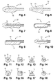
figure 1 représente schématiquement et partiellement, en coupe axiale, un exemple de dispositif de conditionnement et d'application conforme à l'invention, - la
figure 2 représente isolément et partiellement, de manière schématique, en coupe axiale, l'applicateur du dispositif de lafigure 1 , - les
figures 3 illustrent des variantes de réalisation de l'applicateur, en particulier de la fixation de l'organe d'application sur la tige,et 4 - les
figures 5 à 10 illustrent en coupe longitudinale différentes formes de l'enveloppe de l'organe d'application, - les
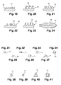
figures 11 à 18 illustrent en coupe transversale différentes formes de l'organe d'application, - les
figures 19 à 23 illustrent des exemples d'éléments d'application de différentes formes, - la
figure 24 illustre un exemple d'organe d'application comportant une surface d'application floquée, - les
figures 25 à 27 illustrent différentes configurations d'éléments d'application, - les
figures 28 à 30 illustrent en coupe longitudinale différentes formes de l'organe d'application, - les
figures 31 à 41 illustrent divers exemples de sections transversales de l'âme de l'organe d'application, - la
figure 42 illustre une variante de réalisation de l'applicateur.
- the
figure 1 shows schematically and partially, in axial section, an example of a packaging device and application according to the invention, - the
figure 2 represents in isolation and partially, schematically, in axial section, the applicator of the device of thefigure 1 , - the
Figures 3 and 4 illustrate alternative embodiments of the applicator, in particular the attachment of the applicator member on the rod, - the
Figures 5 to 10 illustrate in longitudinal section different shapes of the envelope of the application member, - the
Figures 11 to 18 illustrate in cross-section different forms of the application member, - the
Figures 19 to 23 illustrate examples of application elements of different shapes, - the
figure 24 illustrates an example of an applicator member comprising a flocked application surface, - the
Figures 25 to 27 illustrate different configurations of application elements, - the
Figures 28 to 30 illustrate in longitudinal section different forms of the application member, - the
Figures 31 to 41 illustrate various examples of cross-sections of the core of the applicator member, - the
figure 42 illustrates an alternative embodiment of the applicator.
Le dispositif 1 de conditionnement et d'application représenté à la
Le récipient 2 comporte un corps 4 muni d'un col 5 dans lequel est logé, dans l'exemple considéré, un organe d'essorage 6.The
L'applicateur 3 comporte une tige 8, d'axe longitudinal X, se raccordant à une extrémité à un organe de préhension 9 qui constitue également un capuchon de fermeture étanche du récipient 2.The
Dans l'exemple illustré, la tige est cylindrique, de diamètre constant, mais on ne sort pas du cadre de l'invention lorsque la tige 8 comporte un retreint, par exemple situé au niveau de l'organe d'essorage 6, et notamment d'une lèvre de ce dernier, afin de ne pas la déformer pendant le stockage quand le récipient 2 est fermé.In the illustrated example, the rod is cylindrical, of constant diameter, but it is not beyond the scope of the invention when the
La tige 8 porte à l'autre extrémité un organe d'application 10 qui a été représenté isolément sur la
Sur cet exemple la tige 8 est réalisée d'une seule pièce. Mais on peut en variante, comme on l'a représenté
La tige 8 peut comporter, comme illustré sur la
L'organe d'essorage 6 est par exemple adapté à essorer la tige 8 et l'organe d'application 10.The
Selon la forme de l'organe d'application 10 et la matière dans laquelle il est réalisé, ainsi que la forme et la nature de l'organe d'essorage 6, on peut avoir ou non une déformation de l'organe d'application 10 à la traversée de l'organe d'essorage 6.Depending on the shape of the
On peut par exemple choisir l'organe d'essorage 6 en fonction de la quantité de produit que l'on souhaite conserver sur l'organe d'application 10 après sa sortie du récipient 2.For example, the
A la fois l'organe d'application 10 et l'organe d'essorage 6 peuvent se déformer lors du retrait de l'applicateur 3, par exemple.Both the
L'organe d'essorage 6 peut être de tout type et par exemple comporter une lèvre flexible définissant à son extrémité inférieure un orifice circulaire, de diamètre sensiblement égal à celui de la tige 8. En variante, l'orifice d'essorage peut présenter un diamètre différent et/ou une forme non circulaire.The
L'organe d'essorage 6 peut être réalisé dans une matière plastique, par exemple en PE, PP, POM, PET, nitrile, silicone, EPDM, SIS ou SEBS, un élastomère polyester thermoplastique tel que par exemple celui connu sous la marque HYTREL®, un élastomère thermoplastique tel que par exemple celui connu sous la dénomination SANTOPRENE®, cette liste n'étant limitative.The
L'organe d'essorage 6 peut encore ne pas être rapporté sur le col mais moulé ou surmoulé sur celui-ci.The
L'organe d'essorage peut également comporter une ouverture de diamètre variable pour faire varier sa section de passage pour l'organe d'application et/ou sa déformabilité.The wiper member may also include an opening of variable diameter to vary its passage section for the applicator member and / or its deformability.
L'organe d'essorage 6 peut comporter une lèvre d'essorage ondulée qui peut se déployer au passage de l'organe d'application.The
L'organe d'essorage peut encore être différent et se présenter sous la forme d'un bloc de mousse.The wiper member may still be different and be in the form of a block of foam.
Si on se réfère maintenant à la
L'organe d'application 10 comporte une portion centrale 11 formant une âme relativement rigide et une enveloppe externe 12, entourant l'âme, portant des éléments d'application 13 sous forme de poils ou dents. L'enveloppe est réalisée en matière plus souple que l'âme de façon à obtenir une brosse molle, flexible, très douce à l'application.The
L'enveloppe est par exemple réalisée en élastomère, notamment thermoplastique, PEBD, PVC, PU, polyester élastomère thermoplastique, EPDM, PDM, EVA, SIS, SEBS, SBS, latex, silicone, nitrile, butyl, polyuréthane, polyéther bloc amide, polyester.The envelope is for example made of elastomer, in particular thermoplastic, LDPE, PVC, PU, polyester thermoplastic elastomer, EPDM, PDM, EVA, SIS, SEBS, SBS, latex, silicone, nitrile, butyl, polyurethane, polyether block amide, polyester .
L'enveloppe 12 comporte une zone d'application 100 portant les éléments d'application 13 sur sa surface extérieure et une zone de fixation 200 à une extrémité, servant à la fixation de l'organe d'application sur la tige. Selon l'exemple illustré, la zone de fixation 200 présente un diamètre réduit par rapport à la majeure partie de la zone d'application 100 de façon à être insérée dans le logement 7 de la tige 8.The
L'enveloppe définit une cavité interne 14 dans laquelle est insérée l'âme. La cavité 14 est allongée et s'étend depuis la zone de fixation 200, où elle est débouchante, jusqu'à l'autre extrémité de l'enveloppe, où elle ne débouche pas.The envelope defines an
Selon l'exemple illustré à la
En outre, selon l'exemple illustré
Selon l'exemple de la
Selon l'exemple illustré, la surface de l'enveloppe définissant la cavité 14 est lisse.According to the illustrated example, the surface of the envelope defining the
Selon l'exemple illustré
En variante, la zone d'application 100 de l'enveloppe peut avoir une forme ovale comme à la
La zone d'application 100 de l'enveloppe peut avoir une section transversale circulaire comme on le voit
La zone d'application 100 de l'enveloppe peut également comporter des profils différents de part et d'autre d'un plan médian de l'organe d'application comme dans l'exemple de la
La zone d'application 100 de l'enveloppe définit à l'extérieur une surface d'application 15.The
La surface d'application 15 peut comporter des éléments d'application 13 répartis sous forme d'une ou plusieurs rangées, identiques ou différentes. Les rangées s'étendent le long de l'enveloppe par exemple.The
Les
Les éléments d'application 13 peuvent avoir toute forme. Ils peuvent être sous forme de dents triangulaires avec des bases jointives comme on le voit à la
Le cas échéant, l'organe d'application peut subir, après moulage, une opération de traitement mécanique des éléments d'application, par exemple une action de meulage, le cas échéant au contact d'une surface chaude ou froide, des exemples de procédés de traitement de dents étant décrits dans les demandes de brevet
Les éléments d'application 13 peuvent également être recouverts d'un revêtement de flocage. Le revêtement de flocage peut comporter des fibres toutes identiques ou encore un mélange de fibres différentes.The
La surface d'application 15 peut également être dépourvue d'éléments d'application et être lisse. Elle peut aussi être recouverte d'un revêtement de flocage 17 comme illustré à la
La surface d'application 15 peut également définir un pas de vis sur toute sa longueur.The
Des éléments d'application sous forme de dents peuvent également être disposés à l'extrémité de l'enveloppe 12 opposée à la zone de fixation, les dents étant disposées sensiblement parallèlement à une portion d'extrémité de l'âme. Trois dents 130 sont par exemple disposées à la pointe de l'organe d'application comme on l'a illustré
Pour rigidifier l'organe d'application 10, on prévoit une âme 11 à l'intérieur de la cavité 14 de l'enveloppe.To stiffen the
En particulier, l'âme peut être rigide de façon à conférer à l'applicateur la force nécessaire pour appliquer le produit sur les cils. Elle peut être flexible de manière à conférer de la souplesse à l'application. Elle peut être réalisée en matériau déformable à mémoire de forme, ou encore sans mémoire de forme de façon à permettre d'obtenir, comme on le verra plus loin dans la description, des formes particulières d'applicateur.In particular, the core may be rigid so as to give the applicator the force necessary to apply the product on the eyelashes. It can be flexible to provide flexibility to the application. It can be made of deformable shape memory material, or without shape memory so as to obtain, as will be seen later in the description, particular forms of applicator.
L'âme 11 est par exemple formée par un élément allongé métallique, par exemple un fil de fer, ou encore par un élément allongé réalisé en plastique. L'âme est par exemple réalisée en matériau thermoplastique choisi dans la liste suivante : PEHD, PEBD, PE linéaire, PP, PT, POM, PA, PET, PBT.The
Selon l'exemple illustré à la
On ne sort pas du cadre de la présente invention en utilisant une âme 11 courbe, présentant une seule courbure comme on le voit à la
En variante, l'âme 11 peut aussi comporter deux portions droites 11a et 11b qui forment un angle entre elles comme on le voit à la
L'âme peut aussi comporter une première portion d'axe longitudinal confondu avec l'axe longitudinal de la tige qui s'étend à l'intérieur de celle-ci, et une deuxième portion, située à l'extérieur de la tige qui forme un angle non nul avec la première.The core may also comprise a first portion of longitudinal axis coinciding with the longitudinal axis of the rod which extends inside thereof, and a second portion, located outside the rod which forms a non-zero angle with the first.
Comme on le voit sur les
L'âme peut aussi avoir une section transversale de toute autre forme comme on l'a représenté sur les
Selon l'exemple illustré
Selon une variante illustrée
Selon l'exemple de la
L'enveloppe 12 est donc fixée à l'âme 11, uniquement dans la zone de fixation 200, à son extrémité. Par contre, l'enveloppe 12 est libre par rapport à l'âme 11 sur toute la zone d'application 100, c'est-à-dire que l'enveloppe 12 n'est pas fixée ou attachée à l'âme dans la zone d'application. Cela permet à cette partie de l'enveloppe de bouger, même sensiblement, par rapport à l'âme lorsqu'on la sollicite sur sa surface extérieure, notamment manuellement. Elle peut par exemple tourner par rapport à l'âme de façon à se vriller sur l'âme. Elle peut aussi s'étirer selon l'axe longitudinal de l'âme. Cela permet de réduire les contraintes qui sont appliquées sur la surface d'application 15 de l'enveloppe, et notamment sur les éléments d'application 13, lors de l'application sur les cils par exemple ou lors du passage de l'applicateur au travers de l'essoreur 6.The
Pour réaliser l'applicateur de la
La zone de fixation 200 de l'organe d'application 10 est ensuite insérée dans le logement 7 de la tige, l'âme étant libre par rapport à l'enveloppe sur toute la zone d'application 100. On sertit ensuite l'extrémité de la tige, entourant le logement 7 sur la zone de fixation 200 de l'enveloppe qui elle-même est sertie sur l'âme. Cette étape de sertissage se fait par exemple à chaud ou à froid. L'enveloppe 12 se resserre ainsi sur l'âme, sur la zone de fixation 200, de façon à être retenue sur l'âme.The
L'enveloppe 12 souple est ainsi prise en sandwich entre la tige 8 rigide et l'âme 11 rigide. L'organe d'application 10 est ainsi parfaitement retenu sur la tigeThe
Lorsque la tige 8 comporte une portion intermédiaire 16 comme illustré
Selon la variante illustrée
Lorsque l'âme 11 est courbe ou encore comporte une portion formant un angle avec une autre portion comme dans les modes de réalisation illustrés sur les
Cette déformation pourra aussi se faire par l'utilisatrice, avant utilisation, qui aura au préalable acheté un applicateur avec une âme droite.This deformation can also be done by the user, before use, who has previously purchased an applicator with a straight soul.
Dans la description détaillée qui précède, il a été fait référence à des modes de réalisation préférés de l'invention. II est évident que des variantes peuvent y être apportées sans s'écarter de l'invention telle que revendiquée ci-après.In the foregoing detailed description, reference has been made to preferred embodiments of the invention. It is obvious that variations can be made without departing from the invention as claimed below.
En particulier, lorsque le récipient comporte un organe d'essorage au travers duquel l'organe d'application est retiré, l'organe d'application peut être soumis ou non à des vibrations au moment du passage à travers l'organe d'essorage, ce qui peut permettre d'obtenir un essorage de l'organe d'application différent de celui qui existe en l'absence de vibration de l'organe d'application. L'utilisateur peut ainsi par exemple choisir entre au moins deux degrés d'essorage de l'organe d'application, selon que l'organe d'application vibre ou non au moment de la traversée de l'organe d'essorage.In particular, when the container comprises a wiper member through which the applicator member is removed, the applicator member may or may not be subjected to vibrations when passing through the wiper member. , which may allow to obtain a spin of the applicator member different from that which exists in the absence of vibration of the applicator member. The user can thus for example choose between at least two degrees of wringing of the applicator member, depending on whether or not the applicator member vibrates when the wiper member passes through.
Le produit peut encore être appliqué au moyen d'un dispositif d'aide à l'application du produit, ce dispositif comportant des moyens de fixation amovible à au moins un doigt, une main ou un poignet, ou étant tenu dans la main, et une source vibrante permettant de produire des variations.The product may also be applied by means of a device for assisting the application of the product, this device comprising means for removable attachment to at least one finger, a hand or a wrist, or being held in the hand, and a vibrating source for producing variations.
L'âme et/ou l'enveloppe de l'organe d'application peut (peuvent) être magnétisable(s).The core and / or the envelope of the applicator member may be magnetizable (s).
Claims (35)
Applications Claiming Priority (1)
| Application Number | Priority Date | Filing Date | Title |
|---|---|---|---|
| FR0655840A FR2910255B1 (en) | 2006-12-21 | 2006-12-21 | APPLICATOR FOR APPLYING A COSMETIC PRODUCT ON KERATINIC MATERIALS |
Publications (2)
| Publication Number | Publication Date |
|---|---|
| EP1935279A1 true EP1935279A1 (en) | 2008-06-25 |
| EP1935279B1 EP1935279B1 (en) | 2016-06-29 |
Family
ID=38328243
Family Applications (1)
| Application Number | Title | Priority Date | Filing Date |
|---|---|---|---|
| EP07122332.5A Active EP1935279B1 (en) | 2006-12-21 | 2007-12-05 | Applicator for applying a cosmetic product to keratinous materials |
Country Status (4)
| Country | Link |
|---|---|
| US (1) | US8210763B2 (en) |
| EP (1) | EP1935279B1 (en) |
| ES (1) | ES2594623T3 (en) |
| FR (1) | FR2910255B1 (en) |
Cited By (17)
| Publication number | Priority date | Publication date | Assignee | Title |
|---|---|---|---|---|
| WO2009030426A2 (en) * | 2007-08-31 | 2009-03-12 | Geka Brush Gmbh | Part of a cosmetic unit |
| EP2168450A1 (en) * | 2007-07-17 | 2010-03-31 | Shiseido Company, Ltd. | Cosmetic applicator |
| CN101843401A (en) * | 2009-03-27 | 2010-09-29 | 欧莱雅 | Metal applicator |
| EP2332443A1 (en) | 2009-12-08 | 2011-06-15 | L'Oréal | Applicator for applying a product to eyelashes and/or eyebrows |
| WO2013153525A1 (en) | 2012-04-11 | 2013-10-17 | L'oreal | Applicator for applying a cosmetic product to the eyelashed and/or eyebrows |
| WO2014019989A1 (en) * | 2012-08-01 | 2014-02-06 | L'oreal | Cosmetic product applicator, device and associated method |
| US8783268B2 (en) | 2008-07-16 | 2014-07-22 | L'oreal | Applicator for combing the eyelashes or the eyebrows, or for applying a composition thereto |
| WO2014203212A1 (en) * | 2013-06-20 | 2014-12-24 | L'oreal | Applicator for applying a product to the eyebrows, eyelashes or the skin |
| WO2014203213A1 (en) * | 2013-06-20 | 2014-12-24 | L'oreal | Applicator for applying a product to the eyebrows |
| FR3007256A1 (en) * | 2013-06-20 | 2014-12-26 | Oreal | APPLICATOR FOR APPLYING A PRODUCT ON THE SKIN |
| FR3007257A1 (en) * | 2013-06-20 | 2014-12-26 | Oreal | APPLICATOR TO APPLY A PRODUCT TO THE EYE |
| FR3023458A1 (en) * | 2014-07-11 | 2016-01-15 | Albea Services | APPLICATOR FOR COSMETIC PRODUCT AND ASSOCIATED PACKAGING AND APPLICATION ASSEMBLY |
| WO2017003506A1 (en) | 2015-06-30 | 2017-01-05 | Elc Management Llc | Molded mascara brush head with rake-like teeth |
| FR3060278A1 (en) * | 2016-12-21 | 2018-06-22 | L V M H Recherche | COSMETIC PRODUCT APPLICATOR DEVICE WITH FLEXIBLE APPLICATOR ELEMENT |
| EP3466299A4 (en) * | 2017-08-21 | 2020-01-01 | Cos Nine Co,. Ltd. | Magnetic mascara |
| US20200196735A1 (en) * | 2017-09-05 | 2020-06-25 | Outinfutures Co., Ltd. | Mascara |
| US20210093068A1 (en) * | 2019-10-01 | 2021-04-01 | Mitsubishi Pencil Company, Limited | Hair dye container |
Families Citing this family (24)
| Publication number | Priority date | Publication date | Assignee | Title |
|---|---|---|---|---|
| KR100939239B1 (en) * | 2008-01-23 | 2010-01-29 | (주)알엔디지케이알 | A Cosmetic Brush |
| US8251074B2 (en) * | 2008-02-04 | 2012-08-28 | Zen Design Solutions Limited | Adjustable applicator |
| CN102088888A (en) * | 2008-05-20 | 2011-06-08 | 阿尔康包装美饰服务公司 | Variable pitch mascara brush |
| FR2945417B1 (en) | 2009-05-15 | 2011-08-26 | Oreal | APPLICATION CONDITIONING DEVICE FOR APPLYING A PRODUCT TO LACQUERS AND / OR EYEILS. |
| FR2945418B1 (en) * | 2009-05-15 | 2012-09-21 | Oreal | DEVICE FOR CONDITIONING AND APPLICATION. |
| USD616608S1 (en) | 2009-10-26 | 2010-05-25 | Mary Kay Inc. | Mascara container |
| FR2954060B1 (en) * | 2009-12-22 | 2012-03-02 | Oreal | BRUSH FOR APPLYING A PRODUCT ON THE LASHES AND / OR THE EYE. |
| FR2958134B1 (en) * | 2010-04-06 | 2012-10-26 | Oreal | MIXED APPLICATOR FOR PRODUCT APPLICATION ON LACQUERS |
| US9066573B2 (en) | 2010-06-04 | 2015-06-30 | Zen Design Solutions Limited | Cosmetic applicator |
| WO2011152927A1 (en) * | 2010-06-04 | 2011-12-08 | Zen Design Solutions Limited | Cosmetic applicator |
| DE102010024236A1 (en) * | 2010-06-18 | 2011-12-22 | Geka Gmbh | Molded lip brush |
| FR2969470B1 (en) * | 2010-12-24 | 2015-06-19 | Ile Mvr Soc Civ | NOVEL APPLICATOR DEVICE FOR A FLUID ON KERATIN FIBERS |
| DE202010017159U1 (en) * | 2010-12-30 | 2012-04-03 | Geka Gmbh | Applicator device, in particular for a mascara applicator, cosmetic applicator, in particular mascara applicator comprising the applicator device and application unit comprising the applicator device |
| DE202010017160U1 (en) * | 2010-12-30 | 2012-04-03 | Geka Gmbh | Applicator device, in particular for a cosmetic applicator, applicator, in particular cosmetic applicator comprising the applicator device and application unit, in particular cosmetic unit comprising the applicator device |
| FR2976164B1 (en) * | 2011-06-07 | 2013-07-05 | Oreal | PACKAGING AND APPLICATION DEVICE |
| FR2979525B1 (en) * | 2011-09-01 | 2013-09-27 | Oreal | APPLICATOR FOR APPLYING A PRODUCT ON LACQUERS OR EYEILS. |
| FR3023690B1 (en) * | 2014-07-16 | 2016-07-15 | Albea Services | SPRINKLER FOR A COSMETIC PRODUCT CONTAINER, CONTAINER COMPRISING SUCH A SPINNER AND AN APPLICATOR ASSEMBLY COMPRISING SUCH A CONTAINER |
| FR3024341B1 (en) * | 2014-07-29 | 2016-07-22 | Albea Services | APPLICATOR TIP FOR COSMETIC PRODUCT, APPLICATOR AND APPLICATOR ASSEMBLY |
| FR3036592B1 (en) * | 2015-05-26 | 2017-05-19 | Oreal | PACKAGING AND APPLICATION ASSEMBLY OF A COSMETIC PRODUCT COMPRISING AT LEAST ONE VOLATILE SOLVENT |
| JP7067759B2 (en) * | 2016-08-22 | 2022-05-16 | 紀伊産業株式会社 | Makeup tools |
| KR200488787Y1 (en) * | 2017-03-29 | 2019-03-19 | 주식회사 엘지생활건강 | Mascara |
| FR3070839A1 (en) * | 2017-09-12 | 2019-03-15 | L'oreal | COSMETIC APPLICATOR |
| FR3072255B1 (en) * | 2017-10-12 | 2021-07-16 | Oreal | APPLICATOR FOR THE APPLICATION OF A PRODUCT ON KERATINIC MATERIALS |
| EP4091500A1 (en) * | 2021-05-21 | 2022-11-23 | GEKA GmbH | Applicator with a 3d printed applicator component attached in a special way |
Citations (12)
| Publication number | Priority date | Publication date | Assignee | Title |
|---|---|---|---|---|
| US3921650A (en) * | 1974-12-23 | 1975-11-25 | Max Factor & Co | Cosmetic applicator and container |
| GB2074443A (en) * | 1980-03-21 | 1981-11-04 | Revlon | Cosmetic applicator |
| FR2506581A1 (en) | 1981-05-27 | 1982-12-03 | Oreal | IMPROVED MAKE-UP BRUSH AND, IN PARTICULAR EYELASH BRUSH |
| EP1351592A2 (en) | 2001-01-19 | 2003-10-15 | Beiersdorf AG | Applicator for liquid or paste-like media, in particular decorative cosmetics such as mascara |
| EP1384417A2 (en) | 2002-07-23 | 2004-01-28 | Beiersdorf AG | Scythe-shaped applicator for liquid or pasty media |
| FR2850549A1 (en) | 2003-02-04 | 2004-08-06 | Oreal | Brush for application of products to keratin materials, especially for application of mascara, having at least some of the bristles curved inwards relative to the core |
| FR2852500A1 (en) | 2003-03-20 | 2004-09-24 | Oreal | BRUSH AND CONDITIONING AND APPLICATION DEVICE COMPRISING SUCH A BRUSH |
| EP1475013A1 (en) | 2003-05-09 | 2004-11-10 | Yoon-Hoi Kim | Mascara brush |
| US20050172439A1 (en) | 2002-05-15 | 2005-08-11 | Georg Weihrauch | Method for the production of a bristle structure on a carrier |
| EP1570763A1 (en) * | 2004-03-02 | 2005-09-07 | L'oreal | Make-up or skin care applicator |
| US20060042647A1 (en) | 2004-08-30 | 2006-03-02 | Sarah Vogel | Method and system for mascara application |
| EP1726235A2 (en) * | 2005-05-24 | 2006-11-29 | L'oreal | Storing and applying device |
Family Cites Families (9)
| Publication number | Priority date | Publication date | Assignee | Title |
|---|---|---|---|---|
| US1153118A (en) * | 1913-09-23 | 1915-09-07 | Grant C Kimes | Cleaning-brush. |
| US1300012A (en) * | 1918-05-09 | 1919-04-08 | T S Simms And Company Ltd | Brush. |
| US4498490A (en) * | 1982-07-23 | 1985-02-12 | Max Factor & Co. | Adjustable product applicator |
| DE60005449T2 (en) * | 1999-08-30 | 2004-07-08 | Henlopen Manufacturing Co., Inc. | Container and application element for products for the skin |
| US6309125B1 (en) * | 2000-05-30 | 2001-10-30 | Andrea Peters | Mascara brush applicator |
| US7429141B2 (en) | 2004-03-02 | 2008-09-30 | L'oreal | Applicator for makeup or beauty care products |
| FR2869773B1 (en) * | 2004-05-07 | 2006-07-28 | Oreal | APPLICATOR AND DEVICE FOR CONDITIONING AND DISTRIBUTION HAVING SUCH AN APPLICATOR |
| US7918619B2 (en) * | 2005-05-24 | 2011-04-05 | L'oreal | Packaging and applicator device, and method of making up skin or lips |
| FR2895218B1 (en) * | 2005-12-27 | 2008-02-01 | Techpack Int Sa | COSMETIC PRODUCT APPLICATOR WITH VARIABLE CONFIGURATION |
-
2006
- 2006-12-21 FR FR0655840A patent/FR2910255B1/en not_active Expired - Fee Related
-
2007
- 2007-12-05 EP EP07122332.5A patent/EP1935279B1/en active Active
- 2007-12-05 ES ES07122332.5T patent/ES2594623T3/en active Active
- 2007-12-21 US US12/003,328 patent/US8210763B2/en active Active
Patent Citations (12)
| Publication number | Priority date | Publication date | Assignee | Title |
|---|---|---|---|---|
| US3921650A (en) * | 1974-12-23 | 1975-11-25 | Max Factor & Co | Cosmetic applicator and container |
| GB2074443A (en) * | 1980-03-21 | 1981-11-04 | Revlon | Cosmetic applicator |
| FR2506581A1 (en) | 1981-05-27 | 1982-12-03 | Oreal | IMPROVED MAKE-UP BRUSH AND, IN PARTICULAR EYELASH BRUSH |
| EP1351592A2 (en) | 2001-01-19 | 2003-10-15 | Beiersdorf AG | Applicator for liquid or paste-like media, in particular decorative cosmetics such as mascara |
| US20050172439A1 (en) | 2002-05-15 | 2005-08-11 | Georg Weihrauch | Method for the production of a bristle structure on a carrier |
| EP1384417A2 (en) | 2002-07-23 | 2004-01-28 | Beiersdorf AG | Scythe-shaped applicator for liquid or pasty media |
| FR2850549A1 (en) | 2003-02-04 | 2004-08-06 | Oreal | Brush for application of products to keratin materials, especially for application of mascara, having at least some of the bristles curved inwards relative to the core |
| FR2852500A1 (en) | 2003-03-20 | 2004-09-24 | Oreal | BRUSH AND CONDITIONING AND APPLICATION DEVICE COMPRISING SUCH A BRUSH |
| EP1475013A1 (en) | 2003-05-09 | 2004-11-10 | Yoon-Hoi Kim | Mascara brush |
| EP1570763A1 (en) * | 2004-03-02 | 2005-09-07 | L'oreal | Make-up or skin care applicator |
| US20060042647A1 (en) | 2004-08-30 | 2006-03-02 | Sarah Vogel | Method and system for mascara application |
| EP1726235A2 (en) * | 2005-05-24 | 2006-11-29 | L'oreal | Storing and applying device |
Cited By (33)
| Publication number | Priority date | Publication date | Assignee | Title |
|---|---|---|---|---|
| EP2168450A4 (en) * | 2007-07-17 | 2012-02-29 | Shiseido Co Ltd | Cosmetic applicator |
| EP2168450A1 (en) * | 2007-07-17 | 2010-03-31 | Shiseido Company, Ltd. | Cosmetic applicator |
| WO2009030426A3 (en) * | 2007-08-31 | 2009-06-11 | Geka Brush Gmbh | Part of a cosmetic unit |
| US8528572B2 (en) | 2007-08-31 | 2013-09-10 | Geka Gmbh | Part of a cosmetic unit |
| WO2009030426A2 (en) * | 2007-08-31 | 2009-03-12 | Geka Brush Gmbh | Part of a cosmetic unit |
| US8783268B2 (en) | 2008-07-16 | 2014-07-22 | L'oreal | Applicator for combing the eyelashes or the eyebrows, or for applying a composition thereto |
| RU2458612C2 (en) * | 2009-03-27 | 2012-08-20 | Л'Ореаль | Metallic applicator |
| EP2243393A1 (en) | 2009-03-27 | 2010-10-27 | L'Oréal | Metal applicator |
| FR2943512A1 (en) * | 2009-03-27 | 2010-10-01 | Oreal | METAL APPLICATOR. |
| US8689808B2 (en) | 2009-03-27 | 2014-04-08 | L'oreal | Applicator including inorganic material |
| CN101843401A (en) * | 2009-03-27 | 2010-09-29 | 欧莱雅 | Metal applicator |
| EP2332443A1 (en) | 2009-12-08 | 2011-06-15 | L'Oréal | Applicator for applying a product to eyelashes and/or eyebrows |
| US8684616B2 (en) | 2009-12-08 | 2014-04-01 | L'oreal | Applicator for applying a composition to the eyelashes and/or the eyebrows |
| WO2013153525A1 (en) | 2012-04-11 | 2013-10-17 | L'oreal | Applicator for applying a cosmetic product to the eyelashed and/or eyebrows |
| FR2989254A1 (en) * | 2012-04-11 | 2013-10-18 | Oreal | APPLICATOR FOR THE APPLICATION OF A COSMETIC PRODUCT ON LACQUERS AND / OR THE EYE |
| WO2014019989A1 (en) * | 2012-08-01 | 2014-02-06 | L'oreal | Cosmetic product applicator, device and associated method |
| FR2994068A1 (en) * | 2012-08-01 | 2014-02-07 | Oreal | COSMETIC PRODUCT APPLICATOR, DEVICE AND ASSOCIATED METHOD |
| US9668564B2 (en) | 2012-08-01 | 2017-06-06 | L'oreal | Cosmetic product applicator, device and associated method |
| FR3007256A1 (en) * | 2013-06-20 | 2014-12-26 | Oreal | APPLICATOR FOR APPLYING A PRODUCT ON THE SKIN |
| FR3007257A1 (en) * | 2013-06-20 | 2014-12-26 | Oreal | APPLICATOR TO APPLY A PRODUCT TO THE EYE |
| FR3007260A1 (en) * | 2013-06-20 | 2014-12-26 | Oreal | APPLICATOR TO APPLY A PRODUCT TO THE EYE |
| WO2014203212A1 (en) * | 2013-06-20 | 2014-12-24 | L'oreal | Applicator for applying a product to the eyebrows, eyelashes or the skin |
| WO2014203213A1 (en) * | 2013-06-20 | 2014-12-24 | L'oreal | Applicator for applying a product to the eyebrows |
| FR3023458A1 (en) * | 2014-07-11 | 2016-01-15 | Albea Services | APPLICATOR FOR COSMETIC PRODUCT AND ASSOCIATED PACKAGING AND APPLICATION ASSEMBLY |
| EP3316730A4 (en) * | 2015-06-30 | 2019-02-13 | ELC Management LLC | Molded mascara brush head with rake-like teeth |
| WO2017003506A1 (en) | 2015-06-30 | 2017-01-05 | Elc Management Llc | Molded mascara brush head with rake-like teeth |
| FR3060278A1 (en) * | 2016-12-21 | 2018-06-22 | L V M H Recherche | COSMETIC PRODUCT APPLICATOR DEVICE WITH FLEXIBLE APPLICATOR ELEMENT |
| WO2018115752A1 (en) | 2016-12-21 | 2018-06-28 | L V M H Recherche | Applicator device for cosmetic product with flexible applicator element |
| KR20190097168A (en) * | 2016-12-21 | 2019-08-20 | 엘브이엠에이취 러쉐르쉐 | Cosmetic applicator device with flexible applicator element |
| US11653741B2 (en) | 2016-12-21 | 2023-05-23 | Lvmh Recherche | Applicator device for cosmetic product with flexible applicator element |
| EP3466299A4 (en) * | 2017-08-21 | 2020-01-01 | Cos Nine Co,. Ltd. | Magnetic mascara |
| US20200196735A1 (en) * | 2017-09-05 | 2020-06-25 | Outinfutures Co., Ltd. | Mascara |
| US20210093068A1 (en) * | 2019-10-01 | 2021-04-01 | Mitsubishi Pencil Company, Limited | Hair dye container |
Also Published As
| Publication number | Publication date |
|---|---|
| FR2910255A1 (en) | 2008-06-27 |
| US20090214284A1 (en) | 2009-08-27 |
| FR2910255B1 (en) | 2009-08-21 |
| ES2594623T3 (en) | 2016-12-21 |
| US8210763B2 (en) | 2012-07-03 |
| EP1935279B1 (en) | 2016-06-29 |
Similar Documents
| Publication | Publication Date | Title |
|---|---|---|
| EP1935279B1 (en) | Applicator for applying a cosmetic product to keratinous materials | |
| EP1917883B1 (en) | Applicator for applying a product to the eyelashes or eyebrows | |
| EP1477083B2 (en) | Applicator and container comprising such an applicator | |
| EP2332443B1 (en) | Applicator for applying a product to eyelashes and/or eyebrows | |
| EP0978241B1 (en) | Device for applying make-up having a brush, its production method and application unit using such a device | |
| EP1561394B1 (en) | Device for storing and applying a product comprising a wiping element | |
| EP1247472B1 (en) | Device for storing and applying a product, in particular a cosmetic product | |
| FR2916328A1 (en) | Product e.g. mascara, conditioning and applying device's brush for e.g. eyelash, has connecting element with elongated portions that are spaced and separated from each other by bristles, when brush is in plane perpendicular to core axis | |
| FR2932657A1 (en) | BRUSH WITH MASCARA. | |
| FR3014656A1 (en) | APPLICATOR OF A COSMETIC, MAKE-UP OR CARE PRODUCT, ON LASHES AND / OR EYEBROWS | |
| FR2891708A1 (en) | DEVICE FOR PACKAGING AND APPLYING A PRODUCT. | |
| FR2855380A1 (en) | DEVICE FOR PACKAGING AND APPLYING A PRODUCT, COMPRISING A SPINNER | |
| EP2022366A1 (en) | Packaging and application device containing a wiper having at least one non-radial slit | |
| FR2979807A1 (en) | APPLICATOR FOR APPLYING A PRODUCT ON LACQUERS OR EYEBROWS | |
| EP1977661A1 (en) | Applicator for applying a composition to the eyelashes | |
| FR3014654A1 (en) | APPLICATOR FOR APPLYING A COSMETIC OR CARE PRODUCT TO LACQUERS OR EYEBROWS | |
| EP2938223B1 (en) | Packaging and application system of a cosmetic composition and use of said system | |
| FR3072008A1 (en) | APPLICATOR FOR APPLYING A COSMETIC PRODUCT | |
| FR2916950A1 (en) | Make-up product e.g. mascara, applicator for e.g. eyelashes, has cover surface with two cross-sections whose apexes are angularly shifted around longitudinal axis of application element, where one cross-sections is centered on axis | |
| FR2980677A1 (en) | Applicator i.e. brush for applying mascara e.g. water resistant mascara, to eyelashes and/or eyebrows, has bristles held between turns of core, and tip defining distal end of applicator, where tip is crossed by wire of core | |
| EP3558056B1 (en) | Applicator device for cosmetic product with flexible applicator element | |
| FR3074661B1 (en) | APPLICATOR FOR APPLYING A COSMETIC PRODUCT | |
| FR3004627A1 (en) | APPLICATOR TO APPLY A PRODUCT ON THE LASHES. | |
| FR3035305A1 (en) | BRUSH FOR APPLYING A COSMETIC PRODUCT ON LASHES AND / OR EYCILS COMPRISING SLOTS | |
| FR3013195A1 (en) | ADJUSTABLE APPLICATOR OF A COSMETIC PRODUCT |
Legal Events
| Date | Code | Title | Description |
|---|---|---|---|
| PUAI | Public reference made under article 153(3) epc to a published international application that has entered the european phase |
Free format text: ORIGINAL CODE: 0009012 |
|
| AK | Designated contracting states |
Kind code of ref document: A1 Designated state(s): AT BE BG CH CY CZ DE DK EE ES FI FR GB GR HU IE IS IT LI LT LU LV MC MT NL PL PT RO SE SI SK TR |
|
| AX | Request for extension of the european patent |
Extension state: AL BA HR MK RS |
|
| 17P | Request for examination filed |
Effective date: 20081229 |
|
| AKX | Designation fees paid | ||
| 17Q | First examination report despatched |
Effective date: 20090205 |
|
| RBV | Designated contracting states (corrected) |
Designated state(s): AT BE BG CH CY CZ DE DK EE ES FI FR GB GR HU IE IS IT LI LT LU LV MC MT NL PL PT RO SE SI SK TR |
|
| REG | Reference to a national code |
Ref country code: DE Ref legal event code: 8566 |
|
| GRAP | Despatch of communication of intention to grant a patent |
Free format text: ORIGINAL CODE: EPIDOSNIGR1 |
|
| INTG | Intention to grant announced |
Effective date: 20160316 |
|
| GRAS | Grant fee paid |
Free format text: ORIGINAL CODE: EPIDOSNIGR3 |
|
| GRAA | (expected) grant |
Free format text: ORIGINAL CODE: 0009210 |
|
| AK | Designated contracting states |
Kind code of ref document: B1 Designated state(s): AT BE BG CH CY CZ DE DK EE ES FI FR GB GR HU IE IS IT LI LT LU LV MC MT NL PL PT RO SE SI SK TR |
|
| REG | Reference to a national code |
Ref country code: GB Ref legal event code: FG4D Free format text: NOT ENGLISH |
|
| REG | Reference to a national code |
Ref country code: CH Ref legal event code: EP |
|
| REG | Reference to a national code |
Ref country code: AT Ref legal event code: REF Ref document number: 808390 Country of ref document: AT Kind code of ref document: T Effective date: 20160715 |
|
| REG | Reference to a national code |
Ref country code: IE Ref legal event code: FG4D Free format text: LANGUAGE OF EP DOCUMENT: FRENCH |
|
| REG | Reference to a national code |
Ref country code: DE Ref legal event code: R096 Ref document number: 602007046776 Country of ref document: DE |
|
| REG | Reference to a national code |
Ref country code: LT Ref legal event code: MG4D |
|
| PG25 | Lapsed in a contracting state [announced via postgrant information from national office to epo] |
Ref country code: LT Free format text: LAPSE BECAUSE OF FAILURE TO SUBMIT A TRANSLATION OF THE DESCRIPTION OR TO PAY THE FEE WITHIN THE PRESCRIBED TIME-LIMIT Effective date: 20160629 Ref country code: FI Free format text: LAPSE BECAUSE OF FAILURE TO SUBMIT A TRANSLATION OF THE DESCRIPTION OR TO PAY THE FEE WITHIN THE PRESCRIBED TIME-LIMIT Effective date: 20160629 |
|
| REG | Reference to a national code |
Ref country code: NL Ref legal event code: MP Effective date: 20160629 |
|
| REG | Reference to a national code |
Ref country code: FR Ref legal event code: PLFP Year of fee payment: 10 |
|
| PG25 | Lapsed in a contracting state [announced via postgrant information from national office to epo] |
Ref country code: SE Free format text: LAPSE BECAUSE OF FAILURE TO SUBMIT A TRANSLATION OF THE DESCRIPTION OR TO PAY THE FEE WITHIN THE PRESCRIBED TIME-LIMIT Effective date: 20160629 Ref country code: LV Free format text: LAPSE BECAUSE OF FAILURE TO SUBMIT A TRANSLATION OF THE DESCRIPTION OR TO PAY THE FEE WITHIN THE PRESCRIBED TIME-LIMIT Effective date: 20160629 Ref country code: NL Free format text: LAPSE BECAUSE OF FAILURE TO SUBMIT A TRANSLATION OF THE DESCRIPTION OR TO PAY THE FEE WITHIN THE PRESCRIBED TIME-LIMIT Effective date: 20160629 Ref country code: GR Free format text: LAPSE BECAUSE OF FAILURE TO SUBMIT A TRANSLATION OF THE DESCRIPTION OR TO PAY THE FEE WITHIN THE PRESCRIBED TIME-LIMIT Effective date: 20160930 |
|
| REG | Reference to a national code |
Ref country code: AT Ref legal event code: MK05 Ref document number: 808390 Country of ref document: AT Kind code of ref document: T Effective date: 20160629 |
|
| REG | Reference to a national code |
Ref country code: ES Ref legal event code: FG2A Ref document number: 2594623 Country of ref document: ES Kind code of ref document: T3 Effective date: 20161221 |
|
| PG25 | Lapsed in a contracting state [announced via postgrant information from national office to epo] |
Ref country code: IS Free format text: LAPSE BECAUSE OF FAILURE TO SUBMIT A TRANSLATION OF THE DESCRIPTION OR TO PAY THE FEE WITHIN THE PRESCRIBED TIME-LIMIT Effective date: 20161029 Ref country code: RO Free format text: LAPSE BECAUSE OF FAILURE TO SUBMIT A TRANSLATION OF THE DESCRIPTION OR TO PAY THE FEE WITHIN THE PRESCRIBED TIME-LIMIT Effective date: 20160629 Ref country code: EE Free format text: LAPSE BECAUSE OF FAILURE TO SUBMIT A TRANSLATION OF THE DESCRIPTION OR TO PAY THE FEE WITHIN THE PRESCRIBED TIME-LIMIT Effective date: 20160629 Ref country code: CZ Free format text: LAPSE BECAUSE OF FAILURE TO SUBMIT A TRANSLATION OF THE DESCRIPTION OR TO PAY THE FEE WITHIN THE PRESCRIBED TIME-LIMIT Effective date: 20160629 Ref country code: SK Free format text: LAPSE BECAUSE OF FAILURE TO SUBMIT A TRANSLATION OF THE DESCRIPTION OR TO PAY THE FEE WITHIN THE PRESCRIBED TIME-LIMIT Effective date: 20160629 |
|
| PG25 | Lapsed in a contracting state [announced via postgrant information from national office to epo] |
Ref country code: AT Free format text: LAPSE BECAUSE OF FAILURE TO SUBMIT A TRANSLATION OF THE DESCRIPTION OR TO PAY THE FEE WITHIN THE PRESCRIBED TIME-LIMIT Effective date: 20160629 Ref country code: PT Free format text: LAPSE BECAUSE OF FAILURE TO SUBMIT A TRANSLATION OF THE DESCRIPTION OR TO PAY THE FEE WITHIN THE PRESCRIBED TIME-LIMIT Effective date: 20161031 Ref country code: PL Free format text: LAPSE BECAUSE OF FAILURE TO SUBMIT A TRANSLATION OF THE DESCRIPTION OR TO PAY THE FEE WITHIN THE PRESCRIBED TIME-LIMIT Effective date: 20160629 |
|
| REG | Reference to a national code |
Ref country code: DE Ref legal event code: R097 Ref document number: 602007046776 Country of ref document: DE |
|
| PLBE | No opposition filed within time limit |
Free format text: ORIGINAL CODE: 0009261 |
|
| STAA | Information on the status of an ep patent application or granted ep patent |
Free format text: STATUS: NO OPPOSITION FILED WITHIN TIME LIMIT |
|
| PG25 | Lapsed in a contracting state [announced via postgrant information from national office to epo] |
Ref country code: BE Free format text: LAPSE BECAUSE OF NON-PAYMENT OF DUE FEES Effective date: 20161231 Ref country code: DK Free format text: LAPSE BECAUSE OF FAILURE TO SUBMIT A TRANSLATION OF THE DESCRIPTION OR TO PAY THE FEE WITHIN THE PRESCRIBED TIME-LIMIT Effective date: 20160629 |
|
| 26N | No opposition filed |
Effective date: 20170330 |
|
| STAA | Information on the status of an ep patent application or granted ep patent |
Free format text: STATUS: NO OPPOSITION FILED WITHIN TIME LIMIT |
|
| REG | Reference to a national code |
Ref country code: CH Ref legal event code: PL |
|
| PG25 | Lapsed in a contracting state [announced via postgrant information from national office to epo] |
Ref country code: SI Free format text: LAPSE BECAUSE OF FAILURE TO SUBMIT A TRANSLATION OF THE DESCRIPTION OR TO PAY THE FEE WITHIN THE PRESCRIBED TIME-LIMIT Effective date: 20160629 Ref country code: BG Free format text: LAPSE BECAUSE OF FAILURE TO SUBMIT A TRANSLATION OF THE DESCRIPTION OR TO PAY THE FEE WITHIN THE PRESCRIBED TIME-LIMIT Effective date: 20160929 |
|
| PG25 | Lapsed in a contracting state [announced via postgrant information from national office to epo] |
Ref country code: MC Free format text: LAPSE BECAUSE OF FAILURE TO SUBMIT A TRANSLATION OF THE DESCRIPTION OR TO PAY THE FEE WITHIN THE PRESCRIBED TIME-LIMIT Effective date: 20160629 |
|
| REG | Reference to a national code |
Ref country code: IE Ref legal event code: MM4A |
|
| PG25 | Lapsed in a contracting state [announced via postgrant information from national office to epo] |
Ref country code: CH Free format text: LAPSE BECAUSE OF NON-PAYMENT OF DUE FEES Effective date: 20161231 Ref country code: LI Free format text: LAPSE BECAUSE OF NON-PAYMENT OF DUE FEES Effective date: 20161231 Ref country code: LU Free format text: LAPSE BECAUSE OF NON-PAYMENT OF DUE FEES Effective date: 20161205 |
|
| REG | Reference to a national code |
Ref country code: FR Ref legal event code: PLFP Year of fee payment: 11 |
|
| PG25 | Lapsed in a contracting state [announced via postgrant information from national office to epo] |
Ref country code: IE Free format text: LAPSE BECAUSE OF NON-PAYMENT OF DUE FEES Effective date: 20161205 |
|
| REG | Reference to a national code |
Ref country code: BE Ref legal event code: MM Effective date: 20161231 |
|
| PG25 | Lapsed in a contracting state [announced via postgrant information from national office to epo] |
Ref country code: CY Free format text: LAPSE BECAUSE OF FAILURE TO SUBMIT A TRANSLATION OF THE DESCRIPTION OR TO PAY THE FEE WITHIN THE PRESCRIBED TIME-LIMIT Effective date: 20160629 Ref country code: HU Free format text: LAPSE BECAUSE OF FAILURE TO SUBMIT A TRANSLATION OF THE DESCRIPTION OR TO PAY THE FEE WITHIN THE PRESCRIBED TIME-LIMIT; INVALID AB INITIO Effective date: 20071205 |
|
| PG25 | Lapsed in a contracting state [announced via postgrant information from national office to epo] |
Ref country code: TR Free format text: LAPSE BECAUSE OF FAILURE TO SUBMIT A TRANSLATION OF THE DESCRIPTION OR TO PAY THE FEE WITHIN THE PRESCRIBED TIME-LIMIT Effective date: 20160629 |
|
| PG25 | Lapsed in a contracting state [announced via postgrant information from national office to epo] |
Ref country code: MT Free format text: LAPSE BECAUSE OF FAILURE TO SUBMIT A TRANSLATION OF THE DESCRIPTION OR TO PAY THE FEE WITHIN THE PRESCRIBED TIME-LIMIT Effective date: 20160629 |
|
| PGFP | Annual fee paid to national office [announced via postgrant information from national office to epo] |
Ref country code: ES Payment date: 20230110 Year of fee payment: 16 |
|
| PGFP | Annual fee paid to national office [announced via postgrant information from national office to epo] |
Ref country code: FR Payment date: 20230929 Year of fee payment: 17 |
|
| PGFP | Annual fee paid to national office [announced via postgrant information from national office to epo] |
Ref country code: GB Payment date: 20231012 Year of fee payment: 17 |
|
| PGFP | Annual fee paid to national office [announced via postgrant information from national office to epo] |
Ref country code: IT Payment date: 20231110 Year of fee payment: 17 Ref country code: DE Payment date: 20231010 Year of fee payment: 17 |
|
| PGFP | Annual fee paid to national office [announced via postgrant information from national office to epo] |
Ref country code: ES Payment date: 20240112 Year of fee payment: 17 |