EP1442693A1 - Cleaning implement - Google Patents
Cleaning implement Download PDFInfo
- Publication number
- EP1442693A1 EP1442693A1 EP02768064A EP02768064A EP1442693A1 EP 1442693 A1 EP1442693 A1 EP 1442693A1 EP 02768064 A EP02768064 A EP 02768064A EP 02768064 A EP02768064 A EP 02768064A EP 1442693 A1 EP1442693 A1 EP 1442693A1
- Authority
- EP
- European Patent Office
- Prior art keywords
- scraping
- frame
- cleaning device
- dust
- tire
- Prior art date
- Legal status (The legal status is an assumption and is not a legal conclusion. Google has not performed a legal analysis and makes no representation as to the accuracy of the status listed.)
- Granted
Links
Images









Classifications
-
- A—HUMAN NECESSITIES
- A47—FURNITURE; DOMESTIC ARTICLES OR APPLIANCES; COFFEE MILLS; SPICE MILLS; SUCTION CLEANERS IN GENERAL
- A47L—DOMESTIC WASHING OR CLEANING; SUCTION CLEANERS IN GENERAL
- A47L11/00—Machines for cleaning floors, carpets, furniture, walls, or wall coverings
- A47L11/40—Parts or details of machines not provided for in groups A47L11/02 - A47L11/38, or not restricted to one of these groups, e.g. handles, arrangements of switches, skirts, buffers, levers
- A47L11/4075—Handles; levers
-
- A—HUMAN NECESSITIES
- A47—FURNITURE; DOMESTIC ARTICLES OR APPLIANCES; COFFEE MILLS; SPICE MILLS; SUCTION CLEANERS IN GENERAL
- A47L—DOMESTIC WASHING OR CLEANING; SUCTION CLEANERS IN GENERAL
- A47L11/00—Machines for cleaning floors, carpets, furniture, walls, or wall coverings
- A47L11/32—Carpet-sweepers
- A47L11/33—Carpet-sweepers having means for storing dirt
-
- A—HUMAN NECESSITIES
- A47—FURNITURE; DOMESTIC ARTICLES OR APPLIANCES; COFFEE MILLS; SPICE MILLS; SUCTION CLEANERS IN GENERAL
- A47L—DOMESTIC WASHING OR CLEANING; SUCTION CLEANERS IN GENERAL
- A47L11/00—Machines for cleaning floors, carpets, furniture, walls, or wall coverings
- A47L11/40—Parts or details of machines not provided for in groups A47L11/02 - A47L11/38, or not restricted to one of these groups, e.g. handles, arrangements of switches, skirts, buffers, levers
- A47L11/4013—Contaminants collecting devices, i.e. hoppers, tanks or the like
-
- A—HUMAN NECESSITIES
- A47—FURNITURE; DOMESTIC ARTICLES OR APPLIANCES; COFFEE MILLS; SPICE MILLS; SUCTION CLEANERS IN GENERAL
- A47L—DOMESTIC WASHING OR CLEANING; SUCTION CLEANERS IN GENERAL
- A47L11/00—Machines for cleaning floors, carpets, furniture, walls, or wall coverings
- A47L11/40—Parts or details of machines not provided for in groups A47L11/02 - A47L11/38, or not restricted to one of these groups, e.g. handles, arrangements of switches, skirts, buffers, levers
- A47L11/4036—Parts or details of the surface treating tools
-
- A—HUMAN NECESSITIES
- A47—FURNITURE; DOMESTIC ARTICLES OR APPLIANCES; COFFEE MILLS; SPICE MILLS; SUCTION CLEANERS IN GENERAL
- A47L—DOMESTIC WASHING OR CLEANING; SUCTION CLEANERS IN GENERAL
- A47L11/00—Machines for cleaning floors, carpets, furniture, walls, or wall coverings
- A47L11/40—Parts or details of machines not provided for in groups A47L11/02 - A47L11/38, or not restricted to one of these groups, e.g. handles, arrangements of switches, skirts, buffers, levers
- A47L11/4052—Movement of the tools or the like perpendicular to the cleaning surface
-
- A—HUMAN NECESSITIES
- A47—FURNITURE; DOMESTIC ARTICLES OR APPLIANCES; COFFEE MILLS; SPICE MILLS; SUCTION CLEANERS IN GENERAL
- A47L—DOMESTIC WASHING OR CLEANING; SUCTION CLEANERS IN GENERAL
- A47L11/00—Machines for cleaning floors, carpets, furniture, walls, or wall coverings
- A47L11/40—Parts or details of machines not provided for in groups A47L11/02 - A47L11/38, or not restricted to one of these groups, e.g. handles, arrangements of switches, skirts, buffers, levers
- A47L11/4063—Driving means; Transmission means therefor
- A47L11/4069—Driving or transmission means for the cleaning tools
-
- A—HUMAN NECESSITIES
- A47—FURNITURE; DOMESTIC ARTICLES OR APPLIANCES; COFFEE MILLS; SPICE MILLS; SUCTION CLEANERS IN GENERAL
- A47L—DOMESTIC WASHING OR CLEANING; SUCTION CLEANERS IN GENERAL
- A47L11/00—Machines for cleaning floors, carpets, furniture, walls, or wall coverings
- A47L11/40—Parts or details of machines not provided for in groups A47L11/02 - A47L11/38, or not restricted to one of these groups, e.g. handles, arrangements of switches, skirts, buffers, levers
- A47L11/4072—Arrangement of castors or wheels
-
- A—HUMAN NECESSITIES
- A47—FURNITURE; DOMESTIC ARTICLES OR APPLIANCES; COFFEE MILLS; SPICE MILLS; SUCTION CLEANERS IN GENERAL
- A47L—DOMESTIC WASHING OR CLEANING; SUCTION CLEANERS IN GENERAL
- A47L25/00—Domestic cleaning devices not provided for in other groups of this subclass
- A47L25/005—Domestic cleaning devices not provided for in other groups of this subclass using adhesive or tacky surfaces to remove dirt, e.g. lint removers
-
- Y—GENERAL TAGGING OF NEW TECHNOLOGICAL DEVELOPMENTS; GENERAL TAGGING OF CROSS-SECTIONAL TECHNOLOGIES SPANNING OVER SEVERAL SECTIONS OF THE IPC; TECHNICAL SUBJECTS COVERED BY FORMER USPC CROSS-REFERENCE ART COLLECTIONS [XRACs] AND DIGESTS
- Y10—TECHNICAL SUBJECTS COVERED BY FORMER USPC
- Y10T—TECHNICAL SUBJECTS COVERED BY FORMER US CLASSIFICATION
- Y10T428/00—Stock material or miscellaneous articles
- Y10T428/14—Layer or component removable to expose adhesive
Definitions
- the present invention relates to a cleaning device.
- the dustpan portion does not vertically oscillate independently from the scraping up body with respect to the frame. Accordingly, when the cleaning device is used for cleaning thick-piled carpet, the scraping up body only slips on the upper surface of the carpet according to a slipping motion of the scraping portion on the upper surface of the carpet, so that dust buried in the fibers of the carpet can not be scraped up by the scraping up body. In this case, when the user presses the scraping up body with a strong force in such a manner that the scraping body plunges into the fibers of the carpet, the dustpan portion is pressed strongly against the carpet so as to generate a great resistance against a forward movement, so that operability is deteriorated.
- An object of the present invention is to provide a scraping up body which can securely scrape up dust while smoothly slipping a dustpan portion along a floor surface, even when the dust is buried in thick-piled carpet.
- a cleaning device there is a structure in which a scraping up body is rotatably supported to the frame, and a support axis portion on a leading end portion of a handle is connected to the frame.
- the support axis portion of the handle is connected so as to be prevented from sliding to an upper position with respect to a gravity point position of the frame, a point of force applied to the frame via the handle by the user is far from the scraping up body, the forceis hard to be transmitted to the scraping up body, and a great force is required for rotating the scraping up body. Further, since the force point exists on the gravity point position, there is a risk that the frame pitches forward at a time when the frame moves forward.
- An object of the present invention is to provide a cleaning device in which a cleaning portion can be stably lifted up from a floor surface at a time when the cleaning portion is not being used, and the scraping up body can be stably moved forward while being rotated on the floor surface by use of a small force at a time when the scraping up body is being used.
- the cleaning device there is a structure in which an adhesive roll is rotatably supported to a supporting shaft provided in the frame, and the dust on the floor surface is adsorbed and picked up by an adhesive face of the adhesive roll (Japanese Utility Model Application Laid-open No. 2-12363).
- An object of the present invention is to simplify a structure for supporting the roll and to improve its workability of attaching and detaching the roll.
- An object of the present invention is to reduce the dust which fails to be caught at a time when the scraping up body scrapes up the dust while being in slidable contact with the scooping surface portion of the dustpan portion.
- the other object of the present invention is to lighten the operating force for moving forward the cleaning device.
- the brush constituting the scraping up body is constituted only by fiber members having the same bending elastic property and the same diameter, and a motion of each of the fiber members is uniform at a time when the scraping up body rolls on the floor surface. Accordingly, a forward moving operation feeling of the cleaning device is bumpy, and the continuity of a scraping up operation by the scraping up body is deteriorated.
- the scraping up body constituted by fiber members having a strong bending elasticity such as thick fiber members only the large dust can be scraped up, and in the scraping up body constituted by fiber members having a weak elasticity such as thin fibers, only the small dust can be scraped up.
- An object of the present invention is to make the forward moving operation feeling of the cleaning device lithe, and to continuously scrape up all the large and small dust by means of the scraping up body.
- the dustpan portion does not vertically oscillate independently from the scraping up body with respect to the frame. Accordingly, when using the cleaning device for cleaning thick-piled carpet, the scraping up body only slips on the upper surface of the carpet according to the slipping motion of the dustpan portion on the upper surface of the carpet, so that the dust buried in the fibers of the carpet can not be scraped up by the scraping up body. In this case, the user presses the scraping up body with a strong force in such a manner that the scraping up body is buried in the fibers of the carpet, the dustpan portion is strongly pressed against the carpet so as to generate a great resistance against forward movement, and operability is deteriorated.
- An object of the present invention is to provide a cleaning device in which the scraping up body can securely scrape up the dust while the dustpan portion smoothly slips on the floor surface, even when the dust are buried in the fibers of thick-piled carpet.
- the cleaning device there is a structure in which a scraping up body and a rotating body for rotating an adhesive roll are rotatably supported to a frame in parallel, and the adhesive roll is rotatably arranged on the scraping up body and the rotating body in parallel (Japanese Patent Application No. 2000-335014).
- An object of the present invention is to smoothly rotate the adhesive roll adhering and picking up the dust by the rotating body, in the cleaning device.
- the other object of the present invention is to secure the dust holding capacity of the dustpan portion, and to improve the visibility of the dust accumulating state, in the cleaning device.
- the cleaning device there is a structure in which a brush and a dustpan portion are supported to a frame, a driven wheel is rotated by a drive wheel rolling on the floor surface, and the brush is rotated according to the rotation of the driven wheel, as described in Japanese Patent Publication No. 57-58939.
- the relative speed of the brush is increased with respect to the floor surface by increasing the rotation of the brush in comparison with the rotation of the drive wheel based on a selection of an intermeshing diameter between the drive wheel and the driven wheel, thereby improving dust scraping up capacity by the brush.
- the dust in a range between the wall and the brush can not be cleaned.
- the drive wheel is arranged in a front side in the cleaning forward direction with respect to the driven wheel connected to the brush. Accordingly, the drive wheel exists between the leading end of the cleaning device and the brush, and the cleaning range becomes narrow.
- An object of the present invention is to widen the cleaning range on the floor surface to a portion close to the wall or the like, while increasing the relative speed of the scraping up member of the scraping up body with respect to the floor surface so as to improve the dust scraping up capacity, in the cleaning device.
- the cleaning device there is a structure in which a scraping up body and an adhesive roll are supported to a frame in parallel, and the dust on the floor surface scraped up by the scraping up body are picked up by the adhesive roll, as described in Japanese Patent Application No. 2000-335014.
- the brush of the scraping up body and the adhesive roll are opposed to each other by rotating the adhesive roll in the opposite direction to the rotating direction of the brush, and a moving direction of the surface of the adhesive roll is made in conformity with a moving direction of the brush, in a dust transfer area for transferring the dust scraped up by the brush of the scraping up body to the adhesive roll.
- An object of the present invention is to improve the performance of taking up and picking up the dust such as the hair or the like entwined in the scraping up member of the scraping up body onto the adhesive roll, in the cleaning device.
- a cleaning device comprising:
- the present invention relates to a cleaning device comprising:
- the present invention relates to a cleaning device comprising:
- the present invention relates to a cleaning device comprising:
- the present invention relates to a cleaning device comprising:
- the present invention relates to a cleaning device comprising:
- the present invention relates to a cleaning device comprising:
- the present invention relates to a cleaning device comprising:
- the present invention relates to a cleaning device comprising:
- the present invention relates to a cleaning device comprising:
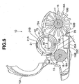
- a cleaning device 10 is structured, as shown in FIG. 1, such that a supporting arm 13 is connected to a leading end portion of a handle 11 via a joint portion 12 in such a manner as to freely oscillate in a lateral direction, and a frame 15 is supported on both side arm portions 13A of the supporting arm 13 via a supporting shaft portion 14 in such a manner as to freely oscillate in a longitudinal direction.
- a flexible scraping up body 16 constituted by a brush is rotatably supported at a front portion of the frame 15 via a rotational shaft 17, a contact rotating body 18 constituted by a roll body is rotatably supported at a rear portion of the frame 15 via a rotational shaft 19, and the scraping up body 16 and the contact rotating body 18 are arranged in parallel.
- the scraping up body 16 is constituted by a scraping up portion 16A (a brush portion) and a tire portion 16B, and a scraping up diameter (a brush diameter) of the scraping up portion 16A is made larger than the tire diameter of the tire portion 16B.
- the contact rotating body 18 is constituted by a roll-shaped contact portion 18A and a tire portion 18B, and is structured such that an outer diameter of the tire portion 18B is made larger than an outer diameter of the contact portion 18A, both side tire portions 18B can roll on a floor surface at both outer sides of a dustpan portion 23 mentioned below, and the tire portions 18B are arranged in an inner side of the dustpan portion 23. Accordingly, the contact portion 18A is isolated from the floor by the dustpan portion 23, whereby it is possible to prevent piles or the like on the floor side from being attached to the contact portion 18A.
- the tire portion 18B is positioned outside the dustpan portion 23.
- a concavo-convex portion may be provided on a surface in the contact portion 18A of the contact rotating body 18.
- the concavo-convex portion corresponds to a structure obtained by applying a rib, a convex portion, a recess portion, a craping surface or the like to a roll surface of the contact portion 18A.
- An adhesive roll 21 is positioned above the scraping up body 16 and the contact rotating body 18, and the adhesive roll 21 rotates so as to interlock with the rotation of the scraping up body 16 and the contact rotating body 18.
- a take in and out port is provided in an upper portion of the frame 15 and is covered by a detachable opening and closing cover or a transparent cover 15A.
- the adhesive roll 21 includes a structure of a take-up roll of an adhesive sheet or a structure having an adhesive elastomer surface reusable by being cleaned.
- the adhesive roll 21 according to the present embodiment is constituted by a take-up roll in which the adhesive sheet 21A is wound around a core 21B and an adhesive surface of the adhesive sheet 21A can be wound out towards an outer side and can be cut.
- a dustpan portion 23 is supported at a rear portion of the scraping up body 16 in the frame 15.
- the dustpan portion 23 has a bottom surface portion 23A being in contact with a floor surface, and a scooping surface portion 23B faces toward the scraping up body 16 with no gap (or via a gap) and forms a curved surface shape (or a flat surface shape), and a concave dust receiving portion 23C. Further, the dustpan portion 23 is arranged so as to isolate the contact portion 18A of the contact rotating body 18 from the floor in the manner mentioned above.
- the dustpan portion 23 is supported to the frame 15 so as to freely oscillate vertically in the manner mentioned above, guides all the dust scraped up by the scraping up portion 16A of the scraping up body 16 to the side of the adhesive roll 21 by the scooping surface portion 23B without missing the dust rearward along the floor surface, by bringing the bottom surface portion 23A and the lowermost end portion of the scooping surface portion 23B into contact with the floor surface with no gap due to the dustpan portion's weights, and the large dust is fed into to the dust receiving portion 23C.
- the cleaning operation by the cleaning device 10 is performed in the following manner.
- the cleaning device 10 can not only move forward but also move backward.
- the dustpan portion 23 is formed in an upward curved shape at a tail end portion of the bottom surface portion 23A, thereby preventing the tail end portion from being caught on the floor surface at a time of backward moving.
- the dust on the carpet is scraped up by the scraping up body 16, and the dust is thereafter adsorbed and picked up by the adhesive roll 21. Since the adhesive roll 21 is not directly in contact with the carpet, it is possible to pick up the dust buried in a deep portion of the fibers in the carpet without injuring the carpet, and it is possible to improve the durability of the adhering performance of the adhesive roll 21.
- the same manner is applied to flooring as to carpet. Since the adhesive roll 21 is not directly in contact with the flooring, the adhesive roll 21 is never strongly adhered to the flooring and is never fixed thereto.
- the dustpan portion 23 is supported to the frame 15 so as to vertically oscillate independently from the scraping up body 16, and the dust receiving portion 23C of the dustpan portion 23 is supported so as to be freely disconnected from the frame 15.
- a front end in the dustpan portion 23 close to the scraping up body 16 is supported to the frame 15 by an oscillating portion 40 (structured such that pins 41 provided on both side surfaces close to the front end of the dustpan portion 23 are engageably inserted so as to vertically move in long holes 42 provided on both side walls of the frame 15) in such a manner as to freely oscillate.
- a hole 51 of an engaging and disengaging portion 50 provided at a rear end at a distance from the scraping up body 16 in the dustpan portion 23 is formed so as to freely engage and disengage an engageable and disengageable pin 52 provided in the frame 15, and the rear end of the dustpan portion 23 is supported so as to be freely disconnected from the frame 15 by detaching the hole 51 from the engageable and disengageable pin 52.
- the engageable and disengageable pin 52 is set to a center axis of oscillation of the dustpan portion 23.
- the oscillating portion 40 is set to a center axis when disconnecting the dustpan portion 23.
- a supporting structure of the frame 15 in operation with the supporting shaft portion 14 at the leading end portion of the handle 11, and a supporting structure of the dustpan portion 23 by the frame 15 are structured as follows.
- the supporting shaft portion 14 of the handle 11 is slidably connected to long holes 30 provided in both side walls of the frame 15.
- the long hole 30 is set upward towards an obliquely rear side in such a manner as to arrange a front end portion in a front lower portion with respect to a gravity point position G of an assembly obtained by assembling the scraping up body 16, the contact rotating body 18 and the adhesive roll 21 in the frame 15, and arrange a rear end portion just above or a rear upper portion with respect to the gravity point position G.
- the supporting shaft portion 14 of the handle 11 is connected to the frame 15 so as to freely slide between an upper position (FIG. 4) with respect to the gravity point position G on the frame 15, and a lower position (FIG. 1) on a side of the scraping up body 16.
- the dustpan portion 23 is supported to the frame 15 so as to vertically oscillate independently from the scraping up body 16, and the dust receiving portion 23C of the dustpan portion 23 is supported so as to be detached from the frame 15.
- the front end close to the scraping up body 16 in the dustpan portion 23 is supported to the frame 15 in a freely oscillating manner by the oscillating portion 40 (structured such that the pins 41 provided on both side surfaces close to the front end of the dustpan portion 23 are engageably inserted so as to vertically move in the long holes 42 provided at both side walls of the frame 15).
- the hole 51 of the engaging and disengaging portion 50 provided in the rear end far away from the scraping up body 16 in the dustpan portion 23 is formed so as to freely engage and disengage the engageable and disengageable pin 52 provided in the frame 15, and the rear end of the dustpan portion 23 is supported so as to be freely disconnected from the frame 15 by detaching the hole 51 from the engageable and disengageable pin 52.
- the engageable and disengageable pin 52 is set to the center axis of oscillation of the dustpan portion 23.
- the oscillating portion 40 is set to the center axis of disconnecting of the dustpan portion 23.
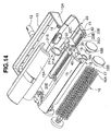
- a roll supporting apparatus 60 for the adhesive roll 21 is structured as follows.
- the roll supporting apparatus 60 is provided with a first side wall 61 and a second side wall 62 opposing to the frame 15.
- the roll supporting apparatus 60 is provided with a first projection 71 having a long protruding length in the first side wall 61, and is provided with a second projection 72 having a short protruding length in the second side wall 62.
- Both projections 71 and 72 are formed in a half cylindrical shape, and a tube surface thereof is arranged downward.
- a distance a from the first side wall 61 to a leading end surface 72A of the second projection 72 is set longer than a length L of the adhesive roll 21 (a > L)
- a distance b from the second side wall 62 to a leading end surface 71A of the first projection 71 is set shorter than the length L of the adhesive roll 21 (L > b).
- the adhesive roll 21 is inclined (two-dot chain line in FIG. 7), one end of the hollow portion 22 in the adhesive roll 21 is inserted to the innermost recesses of the first projection 71, and thereafter, another end of the hollow portion 22 in the adhesive roll 21 is located at the front surface of the second projection 72 without being interfered with the second projection 72.
- another end of the hollow portion 22 is inserted into the second projection 72 by moving the adhesive roll 21 to the side of the second projection 72, whereby the adhesive roll 21 can be supported by both projections 71 and 72.
- the adhesive roll 21 is put on the scraping up body 18 and the contact rotating body 18 in a downward direction in this supported state by both projections 71 and 72, and is supported by both projections 71 and 72 in an upward direction.
- the roll supporting apparatus 60 is provided with a control projection 73 in a part in the peripheral direction of a base portion in the innermost recesses of the first projection 71, and in a part in the side facing to the scraping up body 16 in the present embodiment.
- the control projection 73 is constituted by two ribs 73A and 73B which are apart from each other in the peripheral direction of the first projection 71, however, the control projection 73 may be structured by expanding a part in the peripheral direction of the first projection 71.
- a distance c from the leading end surface 72A of the second projection 72 to the control projection 73 is made shorter than the length L of the adhesive roll 21 (L > c).
- one end surface of the adhesive roll 21 supported by both projections 71 and 72 can be brought into contact with and aligned with a leading end surface 73C of the control projection 73 so as to be opposed thereto, another end of the hollow portion 22 of the adhesive roll 21 controls the movement in a length direction for coming off from the second projection 72, and it is possible to prevent the adhesive roll 21 from dropping out from both projections 71 and 72.
- the adhesive roll 21 in the case of setting an interval formed by the circumscribing circle 74 between the first projection 71 and the control projection 73 with respect to the contact rotating body 18 to e, setting a thickness of the adhesive roll 21 to t, and setting a relation e > t, the adhesive roll 21 can be inserted into the first projection 71 without interfering with the contact rotating body 18, at a time of attaching and detaching the adhesive roll 21 as mentioned above.
- the roll supporting apparatus 60 is structured, in the present embodiment, such that the control projection 73 is provided on the side facing to the scraping up body 16, and the scraping up body 16 is formed as an adhesive roll pressing means.
- the scraping up body 16 brings the brush into pressure contact with the surface of the adhesive roll 21 supported by both projections 71 and 72 in an elastically deflected state so as to press the adhesive roll 21 in a direction in which one end surface of the adhesive roll 21 opposes to the leading end surface 73C of the control projection 73. Accordingly, one end surface of the adhesive roll 21 is stably opposed to the leading end surface 73C of the control projection 73 so as to be collided and aligned therewith.
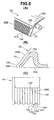
- the scooping surface portion 23B of the scraping up portion 23 is provided with a plurality of convex portions 101 extending along a scraping up direction of the scraping up body 16, and a plurality of grooves 102 formed between the adjacent convex portions 101.
- the scooping surface portion 23B of the scraping up portion 23 is structured such that the leading ends of a plurality of convex portions 61 are extended to the bottom surface portion 23A, so that an edge 103 on the floor surface side of the scooping surface portion 23B of the scraping up portion 23 is provided with a concavo-convex tooth surface 104 extending along a width direction of the edge 103.
- an R surface (a curved surface), for example, having a radius of about 0.3 mm is applied to both side corner portions 105 in the leading end of the convex portion 101 forming the concavo-convex tooth surface 104, in the plan view (FIG.
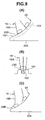
- FIGS. 10(A) to 10(C) can be employed for the leading end shape of the scooping surface portion 23B of the scraping up portion 23, in view of the design of a metal mold for forming the scraping up portion 23.
- leading end Ra a radius of circle
- leading end Rb of the groove 102 the carpet is less frequently caught on.
- the leading end Ra is set to 0.8 mm
- the leading end Rb of the groove 102 is set to 0.3 mm. The dust can be easily scraped up by making the leading end Rb smaller than the leading end Ra.
- a parting line of the metal mold for molding the dustpan portion 23 is provided in the protruding ends of the leading ends Ra and Rb so as to prevent an undercut from being generated, however, since the leading ends Ra and Rb are different, a step is formed between a parting line Pa passing through the protruding end of the leading end Ra and a parting line Pb passing through the protruding end of the leading end Rb, and the metal mold is complex.
- the step of the parting line P is lost by setting the leading end Ra of the convex portion 101 and the leading end Rb of the groove 102 to the same 0.5 mm, whereby the metal mold is made simple.
- a protruding amount (about 1 mm) of the leading end of the convex portion 101 with respect to the leading end of the groove 102 becomes excessive, and there is a possibility that the edge 103 of the scooping surface portion 23B is slightly caught on the carpet.
- the step of the parting line P is lost by setting the leading end Ra of the convex portion 101 and the leading end Rb of the groove 102 to the same 0.5 mm, whereby the metal mold is made simple. Further, the protruding amount (0.4 mm) of the leading end of the convex portion 101 with respect to the leading end of the groove 102 is made smaller by making an angle of incline ⁇ b (for example, 65 degrees) of the leading end side of the convex portion 101 with respect to the bottom surface portion 23A larger than an angle of incline ⁇ a (for example, 50 degrees) of the other portions than the leading end side of the convex portion 101 with respect to the bottom surface portion 23A, whereby the carpet is inhibited from being caught by the edge 103 of the scooping surface portion 23B.
- ⁇ b for example, 65 degrees
- ⁇ a for example, 50 degrees
- the scraping up body 16 of the cleaning device 10 is structured such that the roll-shaped scraping up body is formed around, for example, two core wires 110, by holding each of the center portions of a plurality of fiber members 111 having the same length between the core wires 110, and twisting the core wires 110 so as to fix the fiber members 111.
- the fiber members 111 of the scraping up portion 16A constituting the scraping up body 16 is necessarily provided with a bending elastic property which can satisfy the following conditions.
- the fiber members 111 can elastically deflect based on a control force applied to the handle 11 so as to bring the tire portion 16B into contact with the floor surface, and can elastically restore in such a manner as to scrape up the dust on the floor surface together with the rotation of the tire portion 16B, and (2) the fiber members 111 can generate a bending elastic force (for example, 200 gf) capable of supporting the weight of the adhesive roll 21.
- the fiber members 111 having different bending elastic properties are mixed. Specifically, the thick fiber members 111 and the thin fiber members 111 made of the same raw material are mixed, and more specifically, pig bristles are employed as the fiber members 111.
- the scraping up body 16 is structured such that the diameter of the scraping up portion 16A is set to 40 mm, the diameter of the tire portion 16B is set to 34 mm, and the fiber members 111 made of the pig bristles employ the various fiber members 111 in a range between the thin fiber members 111, for example, having a thickness (diameter) of 0.05 mm and the thick fiber members 111, for example, having a thickness (diameter) of 0.3 mm. Further, the density of fiber implant of the fiber members 111 per a unit axial length (1 mm) of the scraping up portion 16A, and all around the periphery is between 25 and 35 per mm, and more preferably 30 per mm.
- the cleaning device 10 is provided with warping-shaped guide shoes 23E warping up to a front upper side with respect to the floor surface, in both ends of the front edge 23D of the dustpan portion 23.
- the guide shoe 23E is in surface contact with the floor surface, and has no scooping surface portion 23B.
- the portion clamped by the guide shoes 23E on both ends forms an edge (a lowermost end portion) on the floor surface side of the scooping surface portion 23B, and is slidably in contact with the floor surface of the flooring and the tatami mat with no gap.
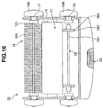
- the cleaning device 10 is structured such that the scraping up body 16 is constituted by a supporting shaft 121, the scraping up body 16A comprising a brush implanted along an entire length of the supporting shaft 121 in an axial direction, and both side tire portions 16B connected to both end portions of the supporting shaft 121, and the rotational shaft 17 mentioned above is provided in the tire portions 16B.
- the scraping up portion 16A may be either in contact with the adhesive roll 21 or in non-contact with the adhesive roll 21.
- Both side tire portions 16B are arranged in both outer sides of the frame 15.
- the rotating body 18 is constituted by a supporting shaft 131, a disc-shaped rotating element 18A fixed to both end side positions in an axial direction of the supporting shaft 131 (a plurality of positions such as three positions or the like in the axial direction may be employed), and both side tire portions 18B connected to both end portions of the supporting shaft 131, and the tire portion 18B is provided with the rotational shaft 19 mentioned above.
- the rotating element 18A is in contact with the adhesive roll 21.
- Both side tire portions 18B are arranged on both outer sides of the frame 15.
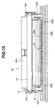
- the dustpan portion 23 has the bottom surface portion 23A being in contact with the floor surface, and the curved (or flat) scooping surface portion 23B faces to the scraping up body 16 with no gap (or via a gap), and a recessed dust receiving portion 23C extends to a range extending forward and backward of the lower side of the rotating element 18A in the rotating body 18.
- the rotating body 18 is constituted by the supporting shaft 131 and the rotating element 18A, the following structures (a) and (b) are provided.
- the supporting shaft 131 and the rotating element 18A of the rotating body 18 are arranged in a space held between the frame 15 and the dustpan portion 23.
- the rotating element 18A of the rotating body 18 is provided with an annular ring 18C such as a silicone rubber O-ring or the like in an outer periphery thereof.
- the annular ring 18C is loaded to an annular groove provided on the rotating element 18A.
- the cleaning device 10 positions the gravity point of the frame 15 and the mounting parts thereof around the supporting shaft portion 14 of the supporting arm 13 in such an inclined state that the scraping up body 16 is positioned in a front side and an upper side of the rotating body 18, as shown in FIG. 17, under a state in which the frame 15 is lifted up by the handle 11 and the supporting arm 13.
- the dust A existing in the front side (close to the scraping up body 16) in the dust receiving portion 23C of the dustpan portion 23 moves to the rear side of the rotating body 18 of the dust receiving portion 23C through the lower side of the supporting shaft 131 of the rotating body 18, in the inclined state mentioned above in which the frame 15 is lifted up, and the dust can be visible from the outer side of the frame 15 and the dustpan portion 23 which are made of a transparent resin.
- the cleaning device 10 is structured such that the scraping up body 16 is constituted by the supporting shaft 121, the scraping up member 16A comprising the brush implanted along an entire length of the supporting shaft 121 in the axial direction, and both side tire portions 16B connected to both end portions of the supporting shaft 121.
- the scraping up member 16A may be in contact with the adhesive roll 21 or in non-contact with the adhesive roll 21.
- Both side tire portions 16B are arranged at both outer sides of the frame 15 in such a manner that the dust is not pinched into the tire portions 16B, however, they may be arranged in an inner side of the frame 15.
- the rotating body 18 is a driving means for the adhesive roll 21, and is constituted by a supporting shaft 131, the disc-shaped rotating elements 18A fixed to both end side positions in an axial direction of the supporting shaft 131 (a plurality of positions such as three positions in the axial direction may be employed), and both side tire portions 18B connected to both end portions of the supporting shaft 131.
- the rotating element 18A is in contact with the adhesive roll 21.
- Both side tire portions 18B are arranged at both outer sides of the frame 15.
- the cleaning device 10 is provided with (A) a scraping up speed increasing means 160 for increasing the rotation of the tire portion 16B so as to transmit to the scraping up member 16A, and (B) an adhesive roll driving means 180 for rotating the adhesive roll 21, in the following manner.
- the scraping up speed increasing means 160 increases the speed of the rotation of the tire portions 16B of the scraping up body 16 so as to transmit to the scraping up member 16A, as shown in FIG. 20.
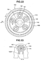
- the scraping up speed increasing means 160 is structured, as shown in FIGS. 21 to 23, such that a hollow shaft portion 162A of a base 162 is inserted and attached to a pivot portion 161 provided on both side walls of the frame 15, a rotation preventing convex portion 162B of the base 162 is locked to a rotation preventing groove 161A of the pivot portion 161 in a rotational direction, and a come-off preventing swelling portion 162C of the base 162 is brought into contact with an inner side surface of the frame 15, whereby rotation prevention and come-off prevention are achieved.
- a sun shaft 163 inserted and engaged with both end portions of the supporting shaft 161 in the scraping up body 16 integrally in the rotational direction is rotatably arranged so as to be inserted to a hollow portion of the hollow shaft portion 162A from an outer side of the base 162, and a sun gear 164 is provided in an outer end portion of the sun shaft 163.
- the sun gear 164 is provided at the center of rotation of the scraping up body 16.
- the cup-shaped tire portion 16B is rotatably fitted to an outer periphery of the base 162.
- a lock ring 165 is screwed to an opening side inner peripheral portion of the tire portion 16B fitted to the base 162.
- the tire portion 16B is directly fitted to a large-diameter portion 162D in the outer periphery of the base 162, and is rotatably fitted to a side portion with respect to the large-diameter portion 162D of the base 162 via the lock ring 165.
- Planetary shafts 166 are provided in a protruding manner at a plurality of positions in the circumferential direction of the center shaft of the tire portion 16B, on an inner side surface of a side wall of the tire portion 16B, preferably, at a plurality of positions with a uniform interval in the circumferential direction (five uniformly arranged positions with a uniform interval in the circumferential direction in the present embodiment), and a planetary gear 167 is pivoted to each of the planetary shafts 166.
- the planetary gear 167 is engaged with the sun gear 164, and revolves around the sun gear 164 while rotating around the planetary shaft 166.
- each of the planetary shafts 166 is formed as a hollow shaft, and an engagement pin 168A provided in a pressing ring 168 preventing the planetary gear 167 from dropping out from the planetary shaft 166 is inserted and attached to the hollow portion of the planetary shaft 166.
- a recess portion 169 to which a leading end shaft portion 163A of the sun shaft 163 is inserted is provided in the center portion of a side wall of the tire portion 16B, and the tire portion 16B and the pressing ring 168 are structured such as to freely rotate relative with respect to the sun shaft 163.
- An inner peripheral portion of the base 162 is formed as a recess portion 171 receiving the planetary gear 167 and the pressing ring 168, and an inner peripheral portion thereof is provided with an internal gear 172 with which the planetary gear 167 is engaged.
- the scraping up speed increasing means 160 speeds up the rotation of the tire portion 16B by a scale a1 so as to transmit to the scraping up member 16A, by a planetary gear train constituted by the sun gear 164, the planetary gear 167 and the internal gear 172.
- a pitch circle diameter of the sun gear 164 is set to d1
- a pitch circle diameter of the planetary gear 167 is set to d2
- a pitch circle diameter of the internal gear 172 is set to d3
- the scraping up speed increasing means 160 is provided with a connection portion to the scraping up member 16A (a connection portion in which the sun shaft 163 is connected to the supporting shaft 121 of the scraping up member 16A) within a projection surface of the tire portion 16B in an axial view of the tire portion 16B.
- the scraping up speed increasing means 160 sets the rotational direction of the scraping up member 16A to the same direction as the rotational direction of the tire portion 16B.
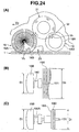
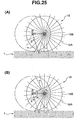
- FIG. 25 shows a speed increasing effect of the scraping up member 16A by the scraping up speed increasing means 160.
- an angle of rotation of the scraping up member 16A is ⁇ at a time when the scraping up member 16A moves from a point A to a point B based on a rotational angle ⁇ of the tire portion 16B.
- the fibers a implanted in the brush of the scraping up member 16A only move from a position of solid line to a position of chain line, the brush implanted fibers a stay at approximately the same position with respect to the floor surface 1, and the brush implanted fibers a only press the dust on the floor surface 1 and can not pick up the hair dust or the like entwined in the carpet or the like.
- the brush implanted fibers a only press the dust on the floor surface 1 and can not pick up the hair dust or the like entwined in the carpet or the like.
- the adhesive roll driving means 180 is structured by the rotating body 18 mentioned above, and rotates the adhesive roll 21 in an opposite direction to the rotational direction of the scraping up member 16A in the scraping up body 16.
- the rotating body 18 rolls on the floor surface while being supported by the frame 15 as mentioned above, and rotates the adhesive roll 21 based on its rotation.
- the rotating body 18 has the tire portion 18B rolling on the floor surface, and disc-like rotating element 18A interlocking with the rotation of the tire portion 18B and rotating the adhesive roll 21 in a state of being in contact with the adhesive roll 21 (the outermost portion of the rotating element 18A is constituted by the annular ring 18D). Since the adhesive roll 21 rotates in contact with the rotating element 18A (the annular ring 18D) without any slip, a circumferential speed Vr of the rotating element 18A (the annular ring 18D) becomes equal to the circumferential speed of the adhesive roll 21.
- the adhesive roll driving means 180 has a speed increasing means 180A for speeding up the rotation of the tire portion 18B in the rotating element 18 so as to transmit to the rotating element 18A (the annular ring 18D).
- the speed increasing means 180A may be constituted by the same planetary gear train as that of the speed increasing means 160 for the scraping up member 16A mentioned above.
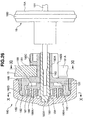
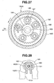
- the speed increasing means 180A is structured, as shown in FIGS. 26 to 28, such that a hollow shaft portion 182A of a base 182 is inserted and attached to a pivot portion 181 provided at both side walls of the frame 15, a rotation preventing convex portion 182B of the base 182 is engaged with a rotation preventing groove 181A of the pivot portion 181 in a rotational direction, and a swelling portion 182C of the base 182 is brought into contact with the inner side surface of the frame 15, whereby rotation prevention and a come-off prevention are achieved.
- a sun shaft 183 which is engaged by integrally inserting to both end portions of the supporting shaft 131 of the rotating body 18, is arranged in a state of being rotatably inserted to the hollow portion of the hollow shaft portion 182A from an outer side of the base 182, and a sun gear 184 is provided in an outer end portion of the sun shaft 183.
- the sun gear 184 is provided at the center of rotation of the rotating body 18.
- the cup-shaped tire portion 18B is rotatably fitted to an outer periphery of the base 182.
- a lock ring 185 is screwed with an inner peripheral portion in an opening side of the tire portion 18B fitted to the base 182.
- the tire portion 18B is directly fitted to a large-diameter portion 182D in an outer periphery of the base 182, and rotatably fitted to a side portion with respect to the large-diameter portion 182D of the base 182 via the lock ring 185.
- Planetary shafts 186 are provided in a protruding manner at a plurality of positions (five positions in the present embodiment) in a peripheral direction of the center shaft of the tire portion 18B and in the inner side surface of the side wall of the tire portion 18B, and a planetary gear 187 is pivoted to each of the planetary shafts 186.
- the planetary gear 187 is engaged with the sun gear 184, and revolves around the sun gear 184 while rotating around the planetary shaft 186.
- each of the planetary shafts 186 is formed as a hollow shaft, and an engagement pin 188A provided in a pressing ring 188 preventing the planetary gear 187 from dropping out from the planetary shaft 186 is inserted and attached to the hollow portion of the planetary shaft 186.
- a recess portion 189 to which a leading end shaft portion 183A of the sun shaft 183 is inserted is provided in a center portion of a side wall of the tire portion 18B, and the tire portion 18B and the pressing ring 188 are structured such as to freely rotate relatively with respect to the sun shaft 183.
- An inner peripheral portion of the base 182 is formed as a recess portion 191 receiving the planetary gear 187 and the pressing ring 188, and an inner peripheral portion thereof is provided with an internal gear 192 with which the planetary gear 187 is engaged.
- the speed increasing means 180A speeds up the rotation of the tire portion 18B by a scale a2 so as to transmit to the scraping up member 18A, by a planetary gear train constituted by the sun gear 184, the planetary gear 187 and the internal gear 192.
- a pitch circle diameter of the sun gear 184 is set to d1
- a pitch circle diameter of the planetary gear 187 is set to d2
- a pitch circle diameter of the internal gear 192 is set to d3
- a diameter of the tire portion 18B is set to Dt (on the assumption of being the same diameter of the tire portion 16B of the scraping up body 16), a rotational speed of the tire portion 18B is set to nt, a diameter of the rotating element 18A is set to Dr, a rotational speed of the rotating element 18A is set to nr, and a circumferential speed of the rotating element 18A is set to Vr, the following formulas (4) to (6) are established.
- the adhesive roll driving means 180 is provided with a connection portion between the speed increasing means 180A and the rotating element 18A (a connection portion in which the sun shaft 183 is connected to the supporting shaft 131 of the rotating element 18A) within a projection surface of the tire portion 18B in an axial view of the tire portion 18B.
- the adhesive roll driving means 180 sets the rotational direction of the rotating element 18A to the same direction as the rotational direction of the tire portion 18B.
- the tire portion 16 When cleaning thick-piled carpet, in the case that a material having a large friction resistance against the fibers or the like of the carpet is employed for the surface material of the tire portion 16B in the scraping up body 16, the tire portion 16 securely speeds up the scraping up member 16A with no slippage. In other words, the tire portion 16B is going to rotate with no slip, and is going to apply rotational torque to the scraping up member 16A. However, the scraping up member 16A is deeply buried in the fibers of the carpet so as to be hard to rotate, and the scraping up member 16A is in a state of slowing the rotation of the tire portion 16B.
- the tire portion 18B of the rotating body 18 floats up from the floor surface, and there is generated a disadvantage that the cleaning can not be performed. Accordingly, the tire portion 16B can slip with respect to the fibers or the like of the carpet by setting the material of the surface of the tire portion 16B in the scraping up body 16 to the material having a certain degree of small friction resistance, and the disadvantage mentioned above is not generated. Therefore, it is possible to lightly clean up. For example, silicone rubber is not good and soft polyethylene is good. In this case, since the scraping up member 16A rotates on the pattern of the surface of the carpet, the scraping up member 16A does not speed up at a degree that the tire portion 16B slips.
- the leading end of the scraping up member 16A is deeply buried in the carpet, and the fibers of the carpet freely deflect so as to reduce the entwining of the dust with respect to the fibers. Accordingly, even in the case that the speed increase of the scraping up member 16A is not sufficient, it is possible to achieve the cleaning and scraping up effect of the scraping up member 16A.
- the dust is entwined with the fibers so as to be hard to pick up, however, in this case, since the rigidity of the fibers of the carpet is firm, the contact pressure of the tire portion 16B becomes higher.
- the friction coefficient of the surface material of the tire portion 18B in the rotating body 18 is high. Since the rotating body 18 is in contact with the carpet only by the tire portion 18B, and the rotating element 18A is separated from the carpet, the tire portion 18B is not prevented from rotating. Accordingly, the rotating element 18A does not slow the rotation of the tire portion 18B even in carpet having thick-piled fibers as mentioned above. Further, in carpet having thick-piled fibers, since the tire portion 18B is mounted on the carpet in a floaty manner, the contact pressure of the tire portion 18B is low, however, in the case that the material of the surface material of the tire portion 18B has a large friction coefficient, it is possible to securely rotate the adhesive roll 21 by the rotating body 18B.
- the adhesive roll 21 smoothly rotates, it is intended to rotate the scraping up member 16A in the direction of scraping up and rotating the scraping up member 16A of the scraping up body 16 which is in contact with the adhesive roll 21. Therefore, the scraping up member 16A is smoothly rotated, and the dust collecting performance is improved.
- silicone rubber is excellent and soft polyethylene is good.
- the speed increasing means 160 for the scraping up member 16A of the scraping up body 16, and the speed increasing means 180A of the rotating element 18A for the adhesive roll 21 may be constituted by a speed increasing means 200, as shown in FIGS. 29 and 30.
- the speed increasing means 200 can be structured by a gear train formed by an engagement between a large-diameter internal gear 201 (a large gear) provided around the rotational center of the tire portion 16B (or 18C), and a small-diameter external gear 202 provided around the supporting shaft 121 (or 18A) (the rotational center) of the scraping up member 16A.
- connection portion between the small-diameter external gear 202 and the scraping up member 16A (or the rotating element 18A) is provided within the projection surface of the tire portion 16B (or 18C) in the axial view of the tire portion 16B (or 18C).
- the rotational direction of the scraping up member 16A becomes the same direction as the rotational direction of the tire portion 16B (or 18C).
- the adhesive roll used in the present invention it is possible to employ a structure in which a tubular sheet is detachably put on a core roll. At this time, an original shape of the tubular sheet is formed in a envelope braid-shaped sheet, and a lot of envelope braid-shaped sheets can be laminated on each other so as to be stored.
- the scraping up body is not limited to the brush, and a sponge, a rubber blade, an elastomer, an elastic projection body and the like may be employed.
- the contact rotating body is not limited to the roll body, and a tire and the like may be employed.
- the floor surface means the tatami mat, the flooring, the carpet and the like, and a significant and specific effect can be achieved with respect to the carpet.
- the scraping up body can securely scrape up the dust while smoothly slipping the dustpan portion on the floor surface, even when the dust is buried in thick-piled carpet.
- the cleaning portion can be stably lifted up from the floor surface at a time when the cleaning portion is not used, and the scraping up body can be stably moved forward while being rotated on the floor surface by use of a small force at a time when the scraping up body is being used.
- the scraping up body can securely scrape up the dust while the dustpan portion smoothly slips on the floor surface, even when the dust is buried in the fibers of thick-piled carpet.
Landscapes
- Nozzles For Electric Vacuum Cleaners (AREA)
- Cleaning Implements For Floors, Carpets, Furniture, Walls, And The Like (AREA)
- Brushes (AREA)
- Cleaning In General (AREA)
Abstract
Description
wherein the dust receiving portion of the dustpan portion is supported so as to be disconnected from the frame.
wherein a control projection is provided in a base portion of the first projection, a distance c from the leading end surface of the second projection to the control projection is made shorter than the length L of the roll, one end surface of the roll supported by both projections is allowed to be brought into contact with the leading end surface of the control projection in an opposing manner, and a roll supporting apparatus capable of preventing the roll from dropping out from both of the projections.
wherein a plurality of grooves extending along a scraping up direction of the scraping up body are provided on the scooping surface portion of the dustpan portion.
wherein guide shoes warping up with respect to a floor surface are provided on both ends of a front edge of the dustpan portion.
the supporting shaft of the rotating body is separated from the adhesive roll in a portion at which the rotating element is not fixed.
wherein the roll driving means is constituted by a rotating body which rolls on the floor surface while being supported to the frame, and rotates the adhesive roll based on the rotation,
wherein the rotating body has a tire rolling on the floor surface, and a rotating element rotating the adhesive roll which is capable of rotatably interlocking with the rotation of the tire, and
wherein a speed increasing means for speeding up the rotation of the tire so as to transmit to the rotating element is provided.
Claims (22)
- A cleaning device comprising:wherein the dustpan portion is supported so as to vertically oscillate independently from the scraping up body with respect to the frame, anda scraping up body rotatably supported to a frame;a dustpan portion supported at a rear portion of the scraping up body in the frame;the dustpan portion having a bottom surface portion being in contact with a floor surface, a scooping surface portion for guiding dust scraped up by the scraping up body, and a dust receiving portion for receiving the dust,
wherein the dust receiving portion of the dustpan portion is supported so as to be disconnected from the frame. - A cleaning device according to claim 1, wherein one end close to the scraping up body in the dustpan portion is supported to the frame by an oscillating portion so as to be freely oscillated, another end far from the scraping up body is supported by an engaging and disengaging pin so as to be freely disconnected from the frame, the engaging and disengaging pin is set as a center shaft of oscillation of the dustpan portion, and the oscillating portion is set as a center shaft of disconnection of the dustpan portion.
- A cleaning device comprising:wherein the connection portion of the handle is connected to the frame so as to be slidable between an upper position with respect to a gravity point position of the frame, and a lower position close to the scraping up body.a scraping up body rotatably supported to a frame; anda connection in a leading end portion of a handle connected to the frame,
- A cleaning device comprising:wherein a first projection having a long protruding length is provided on the first side wall, a second projection having a short protruding length is provided on the second side wall, a distance a from the first side wall to a leading end surface of the second projection is made longer than a length L of a roll, a distance b from the second side wall to a leading end surface of the first projection is made shorter than the length L of the roll, and the roll is allowed to be supported by both projections by inserting one end of a hollow portion of the roll into the first projection and thereafter inserting another end of the hollow portion of the roll into the second projection, anda first side wall;a second side wall; andthe first side wall and the second side wall being opposed to each other,
wherein a control projection is provided in a base portion of the first projection, a distance c from the leading end surface of the second projection to the control projection is made shorter than the length L of the roll, one end surface of the roll supported by both projections is allowed to be brought into contact with the leading end surface of the control projection in an opposing manner, and a roll supporting apparatus capable of preventing the roll from dropping out from both projections. - A cleaning device comprising:wherein the scraping up body is constituted by a brush which is in slidable contact with a scooping surface portion of the dustpan portion so as to scrape up dust, anda scraping up body rotatably supported to a frame; anda dustpan portion supported at a rear portion of the scraping up body in the frame,
wherein a plurality of grooves extending along a scraping up direction of the scraping up body are provided on the scooping surface portion of the dustpan portion. - A cleaning device according to claim 5, wherein an edge close to a floor surface in the scooping surface portion of the dustpan portion is provided with a concavo-convex tooth surface extending along a width direction of the edge.
- A cleaning device comprising:wherein the scraping up body is constituted by a brush formed by mixing fiber members having different bending elastic properties.a scraping up body;a contact rotating body;the scraping up body and the contact rotating body being rotatably supported to a frame in parallel; andan adhesive roll rotatably arranged on the scraping up body and the contact rotating body in parallel,
- A cleaning device according to claim 7, wherein the fiber members are constituted of a thick fiber member and a thin fiber member.
- A cleaning device according to claim 7 or 8, wherein the fiber members are constituted of pig bristles.
- A cleaning device comprising:wherein the dustpan portion is supported so as to vertically oscillate independently from the scraping up body with respect to the frame, anda scraping up body rotatably supported to a frame; anda dustpan portion supported at a rear portion of the scraping up body on the frame;
wherein guide shoes warping up with respect to a floor surface are provided in both ends of a front edge of the dustpan portion. - A cleaning device comprising:wherein the rotating body is constituted by a supporting shaft, and a rotating element which is fixed to a plurality of positions of the supporting shaft so as to be in contact with the adhesive roll, anda scraping up body;a rotating body for rotating an adhesive roll;the scraping up body and the rotating body being rotatably supported to a frame in parallel; andan adhesive roll rotatably arranged on the scraping up body and the rotating body in parallel,
the supporting shaft of the rotating body is separated from the adhesive roll in a portion at which the rotating element is not fixed. - A cleaning device according to claim 11, wherein a dustpan portion is supported at a rear portion of the scraping up body on the frame, and the dustpan portion is extended to a forward and rearward extending range at a lower side of the rotating element of the rotating body, and
wherein the supporting shaft of the rotating body is separated from the dustpan portion at the portion to which the rotating element is not fixed. - A cleaning device according to claim 11 or 12, wherein the rotating body is provided with an annular ring made of a low adhesive material in an outer periphery of the rotating element.
- A cleaning device comprising:wherein a speed increasing means for speeding up the rotation of the tire so as to transfer to the scraping up member is provided, and when viewing in an axial direction of the tire, a connection portion between the speed increasing means and the scraping up member is provided within a projection surface of the tire.a scraping up body and a dust picking means supported to a frame;a tire by which the scraping up body rolls on a floor surface; anda scraping up member which is capable of rotatably interlocking with a rotation of the tire, and scraping up dust from the floor surface to a side of the dust picking means,
- A cleaning device comprising:wherein a speed increasing means for speeding up the rotation of the tire so as to transfer to the scraping up member is provided, and a rotational direction of the scraping up member is set to the same direction as a rotational direction of the tire.a scraping up body and a dust picking means supported to a frame;a tire by which the scraping up body rolls on a floor surface; anda scraping up member which is capable of rotatably interlocking with a rotation of the tire, and scraping up dust from the floor surface to a side of the dust picking means,
- A cleaning device according to claim 14 or 15, wherein the speed increasing means is a planetary gear train constituted by a sun gear which is provided in a rotation center of the scraping up member, a planetary gear which is pivoted to the tire so as to be engaged with the sun gear, and revolves around the sun gear, and an internal gear which is fixed to a side of the frame and engaged with the planetary gear.
- A cleaning device according to claim 14 or 15, wherein the speed increasing means is a gear train constituted by an engagement between a large-diameter internal gear which is provided around a rotation center of the tire, and a small-diameter external gear which is provided around a rotation center of the scraping up member.
- A tire having the speed increasing means according to claim 16 or 17 built-in.
- A cleaning device comprising:wherein the cleaning device has a roll driving means for rotating the adhesive roll in an opposite direction to a rotational direction of the scraping up body,a scraping up body and an adhesive roll supported to a frame in parallel; andthe adhesive roll picking up dust from a floor surface scraped up by the scraping up body,
wherein the roll driving means is constituted by a rotating body which rolls on the floor surface while being supported to the frame, and rotates the adhesive roll based on the rotation,
wherein the rotating body has a tire rolling on the floor surface, and a rotating element rotating the adhesive roll interlocking with the rotation of the tire, and
wherein a speed increasing means for speeding up the rotation of the tire so as to transmit to the rotating element is provided. - A cleaning device according to claim 19, wherein the speed increasing means is a planetary gear train constituted by a sun gear which is provided in a rotation center of the rotating element, a planetary gear which is pivoted to the tire so as to be engaged with the sun gear, and revolves around the sun gear, and an internal gear which is fixed to a side of the frame and engaged with the planetary gear.
- A cleaning device according to claim 19, wherein the speed increasing means is a gear train constituted by an engagement between a large gear which is provided around a rotation center of the tire, and a small gear which is provided around a rotation center of the rotating element.
- A tire having the speed increasing means according to claim 19 built-in.
Priority Applications (1)
| Application Number | Priority Date | Filing Date | Title |
|---|---|---|---|
| EP10164175A EP2229864B1 (en) | 2001-10-03 | 2002-09-25 | Cleaning device |
Applications Claiming Priority (7)
| Application Number | Priority Date | Filing Date | Title |
|---|---|---|---|
| JP2001307972 | 2001-10-03 | ||
| JP2001307985A JP3610328B2 (en) | 2001-10-03 | 2001-10-03 | Cleaning tool |
| JP2001307972A JP3558615B2 (en) | 2001-10-03 | 2001-10-03 | Cleaning tools |
| JP2001307985 | 2001-10-03 | ||
| JP2001307977A JP3613519B2 (en) | 2001-10-03 | 2001-10-03 | Roll support device |
| JP2001307977 | 2001-10-03 | ||
| PCT/JP2002/009875 WO2003030704A1 (en) | 2001-10-03 | 2002-09-25 | Cleaning implement |
Related Child Applications (1)
| Application Number | Title | Priority Date | Filing Date |
|---|---|---|---|
| EP10164175.1 Division-Into | 2010-05-27 |
Publications (3)
| Publication Number | Publication Date |
|---|---|
| EP1442693A1 true EP1442693A1 (en) | 2004-08-04 |
| EP1442693A4 EP1442693A4 (en) | 2009-02-25 |
| EP1442693B1 EP1442693B1 (en) | 2010-08-18 |
Family
ID=27347654
Family Applications (2)
| Application Number | Title | Priority Date | Filing Date |
|---|---|---|---|
| EP10164175A Expired - Lifetime EP2229864B1 (en) | 2001-10-03 | 2002-09-25 | Cleaning device |
| EP02768064A Expired - Lifetime EP1442693B1 (en) | 2001-10-03 | 2002-09-25 | Cleaning implement |
Family Applications Before (1)
| Application Number | Title | Priority Date | Filing Date |
|---|---|---|---|
| EP10164175A Expired - Lifetime EP2229864B1 (en) | 2001-10-03 | 2002-09-25 | Cleaning device |
Country Status (6)
| Country | Link |
|---|---|
| US (1) | US7134160B2 (en) |
| EP (2) | EP2229864B1 (en) |
| CN (1) | CN1292699C (en) |
| DE (1) | DE60237381D1 (en) |
| TW (1) | TWI228406B (en) |
| WO (1) | WO2003030704A1 (en) |
Cited By (10)
| Publication number | Priority date | Publication date | Assignee | Title |
|---|---|---|---|---|
| WO2008038169A3 (en) * | 2006-09-28 | 2008-08-14 | Kimberly Clark Co | Carpet stain removal device |
| WO2008063925A3 (en) * | 2006-11-22 | 2009-01-29 | 3M Innovative Properties Co | Brushing assembly |
| WO2014094869A1 (en) * | 2012-12-21 | 2014-06-26 | Aktiebolaget Electrolux | Cleaning arrangement for a rotatable member of a vacuum cleaner, cleaner nozzle, vacuum cleaner and cleaning unit |
| US9615708B2 (en) | 2013-03-15 | 2017-04-11 | Aktiebolaget Electrolux | Vacuum cleaner agitator cleaner with agitator lifting mechanism |
| US9775477B2 (en) | 2013-05-02 | 2017-10-03 | Aktiebolaget Electrolux | Cleaning nozzle for a vacuum cleaner |
| US9820626B2 (en) | 2008-03-17 | 2017-11-21 | Aktiebolaget Electrolux | Actuator mechanism for a brushroll cleaner |
| US9820624B2 (en) | 2008-03-17 | 2017-11-21 | Aktiebolaget Electrolux | Vacuum cleaner brushroll cleaner configuration |
| US9833115B2 (en) | 2011-10-26 | 2017-12-05 | Aktiebolaget Electrolux | Cleaning nozzle for a vacuum cleaner |
| US9993847B2 (en) | 2012-02-02 | 2018-06-12 | Aktiebolaget Electrolux | Cleaning arrangement for a nozzle of a vacuum cleaner |
| US10117553B2 (en) | 2008-03-17 | 2018-11-06 | Aktiebolaget Electrolux | Cleaning nozzle for a vacuum cleaner |
Families Citing this family (32)
| Publication number | Priority date | Publication date | Assignee | Title |
|---|---|---|---|---|
| JP2005224263A (en) * | 2004-02-10 | 2005-08-25 | Funai Electric Co Ltd | Self-traveling cleaner |
| USD549906S1 (en) * | 2004-04-09 | 2007-08-28 | Euro-Pro Corporation | Surface cleaner |
| USD549907S1 (en) * | 2004-04-14 | 2007-08-28 | Euro-Pro Corporation | Surface cleaner |
| USD549908S1 (en) * | 2004-05-18 | 2007-08-28 | Euro-Pro Corporation | Surface cleaner |
| USD549909S1 (en) * | 2004-06-24 | 2007-08-28 | Euro-Pro Corporation | Surface cleaner |
| US9295362B2 (en) | 2008-03-17 | 2016-03-29 | Aktiebolaget Electrolux | Vacuum cleaner agitator cleaner with power control |
| US20100071721A1 (en) * | 2008-09-22 | 2010-03-25 | Walsh Eric S | Masonry Mold Cleaning Apparatus And Method |
| AU333196S (en) | 2010-02-10 | 2010-10-13 | Kao Corp | Floor wiper |
| US20110247651A1 (en) | 2010-04-13 | 2011-10-13 | Neumann Peter M | Fabric Sweeper |
| DE102010045096A1 (en) * | 2010-09-13 | 2012-03-15 | Carl Freudenberg Kg | Drive system for a cleaning device and cleaning device |
| US8656544B1 (en) | 2011-07-13 | 2014-02-25 | Kenneth Anderson | Sweeper with sweeping elements |
| US9119463B2 (en) * | 2011-10-03 | 2015-09-01 | Pentair Water Pool & Spa, Inc. | Pool cleaner with detachable scrubber assembly |
| AU2012343391B2 (en) | 2011-12-02 | 2016-11-17 | Kao Corporation | Cleaning tool |
| DE102012105734A1 (en) * | 2012-06-29 | 2014-01-02 | Alfred Kärcher Gmbh & Co. Kg | Mobile floor cleaning machine |
| CN104276148B (en) * | 2014-10-08 | 2017-03-29 | 安徽省地坤汽车天窗科技有限公司 | A kind of vehicle dormer window track cleaning device |
| CN204889876U (en) * | 2015-08-25 | 2015-12-23 | 嘉兴捷顺旅游制品有限公司 | Floor sweeper |
| GB2550180B (en) * | 2016-05-11 | 2018-05-02 | Lupe Tech Limited | Cleaner head |
| TWI642399B (en) * | 2016-08-17 | 2018-12-01 | 韓滌清 | Wheel brush broom |
| CN110678271B (en) * | 2018-02-13 | 2022-04-29 | 深圳市赫兹家电有限公司 | Two-way mobile cleaning device |
| US11291345B2 (en) | 2018-08-27 | 2022-04-05 | Techtronic Floor Care Technology Limited | Floor cleaner |
| CN109452903B (en) * | 2018-10-29 | 2020-11-27 | 绍兴大纬针织机械有限公司 | Hair sediment collector based on positive and negative electron charge quantity difference carries out dust absorption |
| WO2020124570A1 (en) * | 2018-12-21 | 2020-06-25 | 深圳市赫兹科技有限公司 | Single-roller cleaner mopping head, dual-roller cleaner mopping head, steering assembly, and floor cleaner |
| CN109770794A (en) * | 2019-03-11 | 2019-05-21 | 安徽特芯电子科技有限公司 | A kind of gap automatic cleaning machine |
| US12239267B2 (en) | 2019-07-02 | 2025-03-04 | Mark Jeffery Giarritta | Four-direction scrubbing carpet shampooer |
| PL4025105T3 (en) | 2019-09-06 | 2024-01-03 | Alfred Kärcher SE & Co. KG | Floor cleaning machine and method for operating a floor cleaning machine |
| CN111350153B (en) * | 2020-03-14 | 2021-08-10 | 深圳市华富环境有限公司 | Energy-saving environment-friendly municipal road cleaning device |
| US11771289B2 (en) * | 2021-10-09 | 2023-10-03 | Michael BLAZ | Handheld sweeper with rotating bristles for removing hair and fur from surfaces |
| CN114098531A (en) * | 2021-11-29 | 2022-03-01 | 江苏旭美特环保科技有限公司 | Intelligent unmanned sweeping machine for station |
| CN114147614A (en) * | 2021-12-08 | 2022-03-08 | 江西莲雄实业有限公司 | Polymer injection molding surface finish device |
| CN114951089B (en) * | 2022-06-30 | 2024-03-08 | 中国人民解放军陆军军医大学第一附属医院 | A kind of scraper and brush dual-purpose cleaner for medical equipment |
| CN117070242B (en) * | 2023-10-16 | 2024-01-26 | 托普工业(江苏)有限公司 | A kind of cracking furnace ash cleaning equipment |
| CN117297446A (en) * | 2023-10-25 | 2023-12-29 | 珠海格力电器股份有限公司 | Base assembly of cleaning equipment and cleaning equipment with base assembly |
Family Cites Families (53)
| Publication number | Priority date | Publication date | Assignee | Title |
|---|---|---|---|---|
| US481269A (en) * | 1892-08-23 | Lawn-sweeper | ||
| US220413A (en) * | 1879-10-07 | Improvement in sweepers | ||
| US336728A (en) * | 1886-02-23 | Lawn-cleaner | ||
| US426882A (en) * | 1890-04-29 | Otis d | ||
| US425695A (en) * | 1890-04-15 | Maeshall e | ||
| US756359A (en) * | 1900-02-08 | 1904-04-05 | John F Hardy | Carpet-sweeper. |
| US666689A (en) * | 1900-06-18 | 1901-01-29 | Finley Lawn Rake Company | Lawn-rake. |
| US894011A (en) * | 1907-02-06 | 1908-07-21 | Otto Kampfe | Sweeper. |
| US1104613A (en) * | 1913-09-24 | 1914-07-21 | Eclipse Folding Machine Company | Suction-cleaner. |
| US1268988A (en) * | 1915-12-06 | 1918-06-11 | Bissell Carpet Sweeper Co | Vacuum-cleaner. |
| GB121688A (en) * | 1918-04-05 | 1919-01-02 | Frank Bernhard Dehn | Vacuum Cleaner. |
| US1613396A (en) * | 1925-04-06 | 1927-01-04 | Sr Julius Keller | Brush gear for vacuum cleaners |
| US1960063A (en) * | 1929-02-16 | 1934-05-22 | Lloyd W Pardee | Suction cleaner |
| US2601697A (en) * | 1944-03-25 | 1952-07-01 | Hoover Co | Adjustable cleaning nozzle for suction cleaners |
| US2536443A (en) * | 1944-04-03 | 1951-01-02 | Eureka Williams Corp | Rug cleaning nozzle |
| US2587038A (en) * | 1946-08-16 | 1952-02-26 | White Aircraft Corp | Carpet sweeper |
| GB635413A (en) * | 1948-04-05 | 1950-04-12 | Wright Howard Clayton | Improvements in carpet sweepers |
| US2949624A (en) * | 1957-11-25 | 1960-08-23 | Electrolux Corp | Suction nozzle |
| US3638267A (en) * | 1969-06-13 | 1972-02-01 | Gunter Leifheit Kg | Floor treating apparatus |
| US3733646A (en) * | 1971-06-14 | 1973-05-22 | G Mein | Vacuum cleaner head with shag rug rake |
| JPS496966A (en) | 1972-04-15 | 1974-01-22 | ||
| JPS496966U (en) * | 1972-04-20 | 1974-01-21 | ||
| JPS5177882A (en) | 1974-12-28 | 1976-07-06 | Nippon Telegraph & Telephone | KEEBURUGAIDOTSUKITAIYASHIKIKAITEIKEEBURUFUSETSUKI |
| JPS5758939A (en) | 1980-09-27 | 1982-04-09 | Tsuchiya Mfg Co Ltd | Manufacture of multitubular heat exchanger |
| JPS59136766A (en) | 1983-01-25 | 1984-08-06 | Minolta Camera Co Ltd | Fixing device |
| GB2134777A (en) * | 1983-02-19 | 1984-08-22 | Prestige Group Plc | Floor sweeper |
| JPS59136766U (en) * | 1983-02-28 | 1984-09-12 | 株式会社リスロン | cleaning tools |
| JPS59160060A (en) | 1983-03-04 | 1984-09-10 | Niigata Eng Co Ltd | Path for exhaust gas of internal-combustion engine equipped with two exhaust ports |
| JPS59160060U (en) * | 1983-04-14 | 1984-10-26 | 日本エ−ス株式会社 | Wheel coaxial reverse rotation brushing device in vacuum cleaner |
| AU567905B2 (en) | 1983-07-25 | 1987-12-10 | Copeland Corporation | Scroll pump |
| JPS6063155A (en) | 1983-09-17 | 1985-04-11 | 松下電工株式会社 | Laminated board for electricity |
| JPS60106568A (en) | 1983-11-16 | 1985-06-12 | Kanto Jidosha Kogyo Kk | Painting method in two tones of metallic color of car body and masking material used for said method |
| JPS60106568U (en) * | 1983-12-26 | 1985-07-20 | シャープ株式会社 | Vacuum cleaner suction tool |
| JPS6137127A (en) * | 1984-07-30 | 1986-02-22 | 株式会社ホ−キイ | Floor surface cleaner |
| JPH01262827A (en) | 1988-04-13 | 1989-10-19 | Yamazaki Sangyo Kk | Manual cleaner |
| JPH0212363U (en) | 1988-07-06 | 1990-01-25 | ||
| CN2046359U (en) * | 1988-12-29 | 1989-10-25 | 丁敏华 | Scavenger |
| JPH0368857A (en) | 1989-08-09 | 1991-03-25 | Terumo Corp | Isfet sensor and manufacture thereof |
| JPH0368857U (en) * | 1989-11-06 | 1991-07-08 | ||
| CN2073724U (en) * | 1990-05-31 | 1991-03-27 | 胡湘燕 | Pushing-driven handy indoor floor-sweeping device |
| US5274445A (en) | 1991-03-01 | 1993-12-28 | Tektronix, Inc. | Three-dimensional testing of video codes |
| JP3161541B2 (en) | 1991-06-26 | 2001-04-25 | 大日本インキ化学工業株式会社 | Isocyanate resin composition |
| KR930001872A (en) * | 1991-07-17 | 1993-02-22 | 원본미기재 | Planetary gear system for vacuum cleaner brush roll |
| US5239721A (en) * | 1991-07-17 | 1993-08-31 | Royal Appliance Mfg. Co. | Planetary gear system for sweeper brush roll |
| JPH0549568A (en) * | 1991-08-29 | 1993-03-02 | Matsushita Electric Ind Co Ltd | Sucking apparatus for electric cleaner |
| CN2131445Y (en) * | 1992-05-16 | 1993-05-05 | 何杰 | Hand-operated cleaning device for carpets |
| JPH06233732A (en) * | 1992-06-24 | 1994-08-23 | John Alan Barhi | Epicyclic gear for brush roll of vacuum cleaner |
| CN2258048Y (en) * | 1995-06-12 | 1997-07-23 | 国中江 | Adjustable cleaner |
| DE19601976C2 (en) * | 1996-01-20 | 2000-10-26 | Fedag Romanshorn Fa | Floor cleaning device with a rotating brush roller |
| JPH105159A (en) * | 1996-06-25 | 1998-01-13 | Kao Corp | Cleaning device and cleaning method |
| CN2279881Y (en) * | 1996-09-11 | 1998-04-29 | 王恭璞 | Combination type multi-function floor cleaning implement |
| JP2000335014A (en) | 1999-05-28 | 2000-12-05 | Dainippon Screen Mfg Co Ltd | Dot image recording method and apparatus |
| JP4738563B2 (en) | 2000-04-21 | 2011-08-03 | キヤノン株式会社 | Semiconductor manufacturing apparatus and device manufacturing method |
-
2002
- 2002-09-25 EP EP10164175A patent/EP2229864B1/en not_active Expired - Lifetime
- 2002-09-25 WO PCT/JP2002/009875 patent/WO2003030704A1/en not_active Ceased
- 2002-09-25 CN CNB028195876A patent/CN1292699C/en not_active Expired - Fee Related
- 2002-09-25 EP EP02768064A patent/EP1442693B1/en not_active Expired - Lifetime
- 2002-09-25 DE DE60237381T patent/DE60237381D1/en not_active Expired - Lifetime
- 2002-09-30 TW TW091122498A patent/TWI228406B/en not_active IP Right Cessation
-
2004
- 2004-04-02 US US10/815,850 patent/US7134160B2/en not_active Expired - Fee Related
Cited By (15)
| Publication number | Priority date | Publication date | Assignee | Title |
|---|---|---|---|---|
| US7921497B2 (en) | 2006-09-28 | 2011-04-12 | Kimberly-Clark Worldwide, Inc. | Carpet stain removal device |
| WO2008038169A3 (en) * | 2006-09-28 | 2008-08-14 | Kimberly Clark Co | Carpet stain removal device |
| WO2008063925A3 (en) * | 2006-11-22 | 2009-01-29 | 3M Innovative Properties Co | Brushing assembly |
| US7856690B2 (en) | 2006-11-22 | 2010-12-28 | 3M Innovative Properties Company | Brushing assembly |
| US9820626B2 (en) | 2008-03-17 | 2017-11-21 | Aktiebolaget Electrolux | Actuator mechanism for a brushroll cleaner |
| US10117553B2 (en) | 2008-03-17 | 2018-11-06 | Aktiebolaget Electrolux | Cleaning nozzle for a vacuum cleaner |
| US9820624B2 (en) | 2008-03-17 | 2017-11-21 | Aktiebolaget Electrolux | Vacuum cleaner brushroll cleaner configuration |
| US9833115B2 (en) | 2011-10-26 | 2017-12-05 | Aktiebolaget Electrolux | Cleaning nozzle for a vacuum cleaner |
| US9839335B2 (en) | 2011-10-26 | 2017-12-12 | Aktiebolaget Electrolux | Cleaning nozzle for a vacuum cleaner |
| US10376114B2 (en) | 2011-10-26 | 2019-08-13 | Aktiebolaget Electrolux | Cleaning nozzle for a vacuum cleaner |
| US9993847B2 (en) | 2012-02-02 | 2018-06-12 | Aktiebolaget Electrolux | Cleaning arrangement for a nozzle of a vacuum cleaner |
| US10045672B2 (en) | 2012-12-21 | 2018-08-14 | Aktiebolaget Electrolux | Cleaning arrangement for a rotatable member of a vacuum cleaner, cleaner nozzle, vacuum cleaner and cleaning unit |
| WO2014094869A1 (en) * | 2012-12-21 | 2014-06-26 | Aktiebolaget Electrolux | Cleaning arrangement for a rotatable member of a vacuum cleaner, cleaner nozzle, vacuum cleaner and cleaning unit |
| US9615708B2 (en) | 2013-03-15 | 2017-04-11 | Aktiebolaget Electrolux | Vacuum cleaner agitator cleaner with agitator lifting mechanism |
| US9775477B2 (en) | 2013-05-02 | 2017-10-03 | Aktiebolaget Electrolux | Cleaning nozzle for a vacuum cleaner |
Also Published As
| Publication number | Publication date |
|---|---|
| TWI228406B (en) | 2005-03-01 |
| EP2229864B1 (en) | 2013-01-23 |
| CN1292699C (en) | 2007-01-03 |
| US20040181888A1 (en) | 2004-09-23 |
| CN1564670A (en) | 2005-01-12 |
| EP1442693A4 (en) | 2009-02-25 |
| US7134160B2 (en) | 2006-11-14 |
| DE60237381D1 (en) | 2010-09-30 |
| WO2003030704A1 (en) | 2003-04-17 |
| EP2229864A1 (en) | 2010-09-22 |
| EP1442693B1 (en) | 2010-08-18 |
Similar Documents
| Publication | Publication Date | Title |
|---|---|---|
| EP1442693B1 (en) | Cleaning implement | |
| US7003840B2 (en) | Cleaning device | |
| EP1123033B1 (en) | Surface-cleaning device with rotatable and pivotable cleaning part | |
| TWI752552B (en) | Vacuum cleaner | |
| EP3827727B1 (en) | Mopping member, mopping apparatus, cleaning robot, and control method for cleaning robot | |
| CA2460417C (en) | A hand-held device for applying a film of adhesive, covering or coloured material onto a substrate | |
| JP5726607B2 (en) | Rotating brush of vacuum cleaner suction tool and suction tool using the same | |
| CN114401657B (en) | Vacuum cleaner with a vacuum cleaner head | |
| US20040034953A1 (en) | Electric mop | |
| JP3868679B2 (en) | Electric vacuum cleaner | |
| JP4133076B2 (en) | Cleaning tool | |
| CN114947614A (en) | Round brush subassembly and cleaning device | |
| JP3610213B2 (en) | Upright vacuum cleaner | |
| CN222367626U (en) | Cleaning assembly and cleaning robot | |
| JP4059721B2 (en) | Cleaning tool | |
| JP4892377B2 (en) | Vacuum cleaner suction and vacuum cleaner | |
| JP2963413B2 (en) | Vacuum cleaner and its suction body | |
| WO2010114207A1 (en) | Mop having protruded bottom | |
| AU2008231622A1 (en) | Mop head | |
| CN215424459U (en) | Main sweeping and sweeping robot of sweeping robot | |
| JP3149161B2 (en) | Vacuum cleaner and suction body of vacuum cleaner | |
| CN211582921U (en) | Floor brush of dust collector and dust collector | |
| JP2004136108A (en) | Electric vacuum cleaner | |
| CN218165111U (en) | Scraping piece and cleaning machine | |
| US20040103497A1 (en) | Cleaning Tool with Rotatably Driven Working Tool |
Legal Events
| Date | Code | Title | Description |
|---|---|---|---|
| PUAI | Public reference made under article 153(3) epc to a published international application that has entered the european phase |
Free format text: ORIGINAL CODE: 0009012 |
|
| 17P | Request for examination filed |
Effective date: 20040430 |
|
| AK | Designated contracting states |
Kind code of ref document: A1 Designated state(s): AT BE BG CH CY CZ DE DK EE ES FI FR GB GR IE IT LI LU MC NL PT SE SK TR |
|
| AX | Request for extension of the european patent |
Extension state: AL LT LV MK RO SI |
|
| A4 | Supplementary search report drawn up and despatched |
Effective date: 20090122 |
|
| 17Q | First examination report despatched |
Effective date: 20090507 |
|
| GRAP | Despatch of communication of intention to grant a patent |
Free format text: ORIGINAL CODE: EPIDOSNIGR1 |
|
| GRAS | Grant fee paid |
Free format text: ORIGINAL CODE: EPIDOSNIGR3 |
|
| GRAA | (expected) grant |
Free format text: ORIGINAL CODE: 0009210 |
|
| AK | Designated contracting states |
Kind code of ref document: B1 Designated state(s): DE FR GB |
|
| REG | Reference to a national code |
Ref country code: GB Ref legal event code: FG4D |
|
| REF | Corresponds to: |
Ref document number: 60237381 Country of ref document: DE Date of ref document: 20100930 Kind code of ref document: P |
|
| PLBE | No opposition filed within time limit |
Free format text: ORIGINAL CODE: 0009261 |
|
| STAA | Information on the status of an ep patent application or granted ep patent |
Free format text: STATUS: NO OPPOSITION FILED WITHIN TIME LIMIT |
|
| 26N | No opposition filed |
Effective date: 20110519 |
|
| REG | Reference to a national code |
Ref country code: DE Ref legal event code: R097 Ref document number: 60237381 Country of ref document: DE Effective date: 20110519 |
|
| REG | Reference to a national code |
Ref country code: FR Ref legal event code: PLFP Year of fee payment: 14 |
|
| PGFP | Annual fee paid to national office [announced via postgrant information from national office to epo] |
Ref country code: GB Payment date: 20150923 Year of fee payment: 14 Ref country code: DE Payment date: 20150922 Year of fee payment: 14 |
|
| PGFP | Annual fee paid to national office [announced via postgrant information from national office to epo] |
Ref country code: FR Payment date: 20150629 Year of fee payment: 14 |
|
| REG | Reference to a national code |
Ref country code: DE Ref legal event code: R119 Ref document number: 60237381 Country of ref document: DE |
|
| GBPC | Gb: european patent ceased through non-payment of renewal fee |
Effective date: 20160925 |
|
| REG | Reference to a national code |
Ref country code: FR Ref legal event code: ST Effective date: 20170531 |
|
| PG25 | Lapsed in a contracting state [announced via postgrant information from national office to epo] |
Ref country code: FR Free format text: LAPSE BECAUSE OF NON-PAYMENT OF DUE FEES Effective date: 20160930 Ref country code: DE Free format text: LAPSE BECAUSE OF NON-PAYMENT OF DUE FEES Effective date: 20170401 Ref country code: GB Free format text: LAPSE BECAUSE OF NON-PAYMENT OF DUE FEES Effective date: 20160925 |