EP1442157B1 - Elektrolysezelle, insbesondere zur elektrochemischen herstellung von chlor - Google Patents
Elektrolysezelle, insbesondere zur elektrochemischen herstellung von chlor Download PDFInfo
- Publication number
- EP1442157B1 EP1442157B1 EP02772323.8A EP02772323A EP1442157B1 EP 1442157 B1 EP1442157 B1 EP 1442157B1 EP 02772323 A EP02772323 A EP 02772323A EP 1442157 B1 EP1442157 B1 EP 1442157B1
- Authority
- EP
- European Patent Office
- Prior art keywords
- current collector
- anode
- gde
- gas diffusion
- diffusion electrode
- Prior art date
- Legal status (The legal status is an assumption and is not a legal conclusion. Google has not performed a legal analysis and makes no representation as to the accuracy of the status listed.)
- Expired - Lifetime
Links
Images


Classifications
-
- C—CHEMISTRY; METALLURGY
- C25—ELECTROLYTIC OR ELECTROPHORETIC PROCESSES; APPARATUS THEREFOR
- C25B—ELECTROLYTIC OR ELECTROPHORETIC PROCESSES FOR THE PRODUCTION OF COMPOUNDS OR NON-METALS; APPARATUS THEREFOR
- C25B1/00—Electrolytic production of inorganic compounds or non-metals
- C25B1/01—Products
- C25B1/24—Halogens or compounds thereof
- C25B1/26—Chlorine; Compounds thereof
-
- C—CHEMISTRY; METALLURGY
- C25—ELECTROLYTIC OR ELECTROPHORETIC PROCESSES; APPARATUS THEREFOR
- C25B—ELECTROLYTIC OR ELECTROPHORETIC PROCESSES FOR THE PRODUCTION OF COMPOUNDS OR NON-METALS; APPARATUS THEREFOR
- C25B9/00—Cells or assemblies of cells; Constructional parts of cells; Assemblies of constructional parts, e.g. electrode-diaphragm assemblies; Process-related cell features
- C25B9/17—Cells comprising dimensionally-stable non-movable electrodes; Assemblies of constructional parts thereof
- C25B9/19—Cells comprising dimensionally-stable non-movable electrodes; Assemblies of constructional parts thereof with diaphragms
-
- C—CHEMISTRY; METALLURGY
- C25—ELECTROLYTIC OR ELECTROPHORETIC PROCESSES; APPARATUS THEREFOR
- C25B—ELECTROLYTIC OR ELECTROPHORETIC PROCESSES FOR THE PRODUCTION OF COMPOUNDS OR NON-METALS; APPARATUS THEREFOR
- C25B9/00—Cells or assemblies of cells; Constructional parts of cells; Assemblies of constructional parts, e.g. electrode-diaphragm assemblies; Process-related cell features
- C25B9/60—Constructional parts of cells
- C25B9/63—Holders for electrodes; Positioning of the electrodes
Definitions
- the invention relates to an electrolytic cell, in particular for the electrochemical production of chlorine from aqueous solutions of hydrogen chloride.
- the object of the invention is to provide an electrolytic cell that works reliably and is easy to handle.
- the electrolysis cell according to the invention has an anode carried by an anode frame, a current collector carried by a cathode frame, and a gas diffusion electrode (GDE) disposed between the anode and the current collector. such as an oxygen-consuming electrode. Furthermore, the electrolysis cell has a cation exchange membrane likewise arranged between the anode and the current collector.
- the anode space is formed of the anode, the anode frame and the back wall and has an inlet and an outlet for the electrolyte.
- the cathode compartment is formed from the current collector, the cathode frame and the rear wall and has an inlet and an outlet for gas, in the case of an oxygen-consuming cathode for oxygen or oxygen-containing gas.
- the GDE is fixed to the current collector. Compared with bonding the GDE to the cation exchange membrane, this has the advantage that, if the GDE or the cation exchange membrane is damaged, both components do not have to be replaced.
- the fixing of the GDE to the current collector has the further advantage that slipping of the GDE is avoided.
- the formation of hydrogen on an exposed current collector is thus also avoided.
- the GDE can be connected by gluing to the current collector. Since gluing of the GDE is to be prevented primarily during installation and in the assembled state, no large forces act on the GDE, since this is clamped between the anode of the cation exchange membrane and the current collector, it is sufficient only to contact the GDE To glue some places with the current collector. For example, in a vertically arranged electrolysis cell, it may be sufficient to glue the GDE only in the upper area. By the provision of little adhesive surfaces or only of glue dots is a deterioration of the behavior of the GDE due to the adhesive, which may have a sealing effect, for example, reduced.
- the GDE is releasably attached to the current collector.
- a detachable attachment can be done for example by sewing on the example as a perforated plate or the like.
- Current collector For this purpose, a suitable plastic thread or the like. Used, which is not attacked by the present in the electrolytic cell chemicals. It is also possible to provide an adhesive connection, such as a hook and loop fastener, between the GDE and the current collector.
- a further advantage of the arrangement according to the invention of the GDE is that the entire surface of the GDE is largely used, since not a part of the surface is covered by pinching between the two frames.
- the GDE is preferably slightly larger than the current collector. During assembly, this protruding beyond the current collector edge of the GDE, for example, then easily pressed into the gap between the current collector and the cathode frame. The outer edge of the GDE thus rests against the cathode frame.
- a sealing element which preferably has substantially the dimensions of the cathode frame, and the GDE are preferably arranged such that a sealing surface of the sealing element pointing in the direction of the anode and the surface of the GDE also pointing in the direction of the anode are arranged in one plane. This ensures that the GDE rests against both the current collector and the cation exchange membrane. This is e.g. prevents buckling or slipping of the GDE.
- the thickness of the sealing element in the assembled state, the thickness of the sealing element preferably corresponds substantially to the thickness of the GDE.
- the current collector terminates essentially with the cathode frame, so that the current collector and the frame top form a plane onto which the sealing element can be placed in the area of the cathode frame and the GDE on the current collector itself, and in turn a common direction in the direction of the anode have pointing plane.
- the current collector is angled at two, for example opposite, or at all four side edges, wherein the edge regions protrude into the cathode space and between the edge regions of Current collector and the cathode frame is formed a gap.
- the current collector and the facing in the direction of the anode space surface of the cathode frame form a plane substantially.
- the GDE is also angled in the edge region in this embodiment. The edges of the GDE are thereby pushed into the gap between current collector and cathode frame.
- the current collector is connected to the cathode frame in such a way that the surface of the current collector does not terminate with the surface of the cathode frame pointing in the direction of the anode, but projects beyond it.
- a thicker seal is then provided, the thickness of which is greater than the distance that the current collector protrudes beyond the cathode frame.
- the seal in turn forms a frame in which the GDE can be inserted.
- the GDE is connected to the current collector e.g. fixed by sewing or with adhesive dots. This has the advantage that when assembling the electrolysis cell, the position of these elements is precisely defined.
- a sealing element which at least partially surrounds the gas diffusion electrode is provided, which has a projection projecting between the cathode frame and the current collector.
- the gas diffusion electrode between the neck and the current collector is held. The holding is done in particular by pinching.
- an elastic wedge for fixing the GDE.
- the elastic wedge is disposed between the current collector and the seal in this embodiment. This may be a single, preferably frame-shaped elastic wedge surrounding the GDE. Furthermore, a plurality of mutually spaced wedges may be provided for fixing the GDE.
- the fixing of the GDE takes place in that the GDE partially engages around or behind the current collector.
- the gripping takes place on two opposite sides of the current collector or, for example, a rectangular current collector along all four sides.
- an edge of the GDE is connected to a bar to allow easy fixation to the current collector.
- the bar which may be, for example, a plastic strip, in this case is designed such that it can be pushed through a gap between the current collector and the cathode frame.
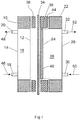
- the electrolytic cell ( FIG. 1 ) has an anode frame 10 which carries an anode 12.
- the anode frame 10 is further connected to a rear wall 14, so that the rear wall 14 and the anode 12, an anode space 16 is formed by the anode frame 10.
- the anode frame 10 has an inlet 18 and an outlet 20.
- a cathode frame 22 carries a current collector 24. Further, the cathode frame 22 has a rear wall 26, so that the cathode frame 22, the current collector 24 and the rear wall 26 form a Kathödenraum 28. Further, the cathode frame 22 is connected to an inlet 30 and an outlet 32.
- the two frames 10,22 are braced against each other in the assembled state of the electrolysis cell.
- a cation exchange membrane 34 is provided for separating the anode compartment 16 from the cathode compartment 28, a cation exchange membrane 34 is provided.
- the cation exchange membrane 34 is larger than the anode 12 and the current collector 24, so that it is also arranged between the two frames 10,22.
- the frames preferably have rectangular outer dimensions.
- the cation exchange membrane is also rectangular, so that the cation exchange membrane is arranged in the entire circumference between the two frames 10,22.
- a sealing element 36 and 38 is provided on both sides of the cation exchange membrane 34.
- a gas diffusion electrode 40 is disposed between the cation exchange membrane 34 and the current collector 24.
- the GDE 40 is connected to the current collector 24 by clamping, gluing, Velcro, sewing or the like. Both the current collector 24 and the anode 12 are connected to electrical terminals.
- the current collector 24 projects beyond the cathode frame 22.
- the seal 38 has a thickness which is greater than the distance between the two surfaces 42, 44 of the cation exchange membrane 34 and the cathode frame 22.
- the protrusion created thereby forms a frame into which the GDE 40 can be inserted.
- the assembly is considerably simplified.
- the outer dimension of the GDE 40 is slightly larger than that of the current collector 24.
- the outer dimension of the GDE 40 is slightly smaller than the dimension of the seal 38 so that it directly on the inside of the Seal 36 is applied.
- hydrochloric acid is supplied to the anode space 16 through the inlet 18 in the direction of the arrow 46.
- the hydrochloric acid is discharged through the outlet 32 in the direction of the arrow 48 again.
- the cathode chamber 28 is supplied through the inlet 30 in the direction of the arrow 50 oxygen, which escapes through the outlet 32 in the direction of the arrow 52 again.
- chlorine is generated in the anode chamber 16, which escapes through the outlet 20 of the anode chamber 16.
- other flow variants for the flow through the anode chamber 16 and the cathode chamber 28 are possible.
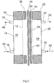
- FIGS. 2 to 5 illustrated embodiments are in principle one of in FIG. 1 shown electrolysis cell similar electrolytic cell, so that the same or similar components are denoted by the same reference numerals.
- the main difference is in the FIG. 2 illustrated embodiment in that the current collector 54 does not protrude beyond the frame 22, but forms a plane with this.
- the current collector 54 is disposed in the same plane as the surface 44 of the cathode frame 22.
- a seal 56 is provided which seals the seal 38 ( FIG. 1 ) replaced.
- the seal 56 is thinner than the seal 38 and may, for example, have the same thickness as the GDE 40.
- the pointing in the direction of the anode 12 surface of the GDE 40 is thus arranged in a plane such as the likewise pointing in the direction of the anode 12 surface of the seal 56. This is the case especially in the assembled state in which the seal 56 can be compressed.
- the components of the two illustrated embodiments and the function of the electrolysis cells shown are identical.
- a seal is provided between the anode frame 10 and the cathode frame 22, which has a projection which projects into the cathode frame 22.
- the approach is thus arranged between the cathode frame 22 and the current collector 24.
- this is angled and fixed between the approach of the seal and the current collector 24 in particular by clamping. This fixation can be performed circumferentially or on two opposite sides of the current collector 24.
- FIG. 4 corresponds to the intended seal the seal 38 ( FIG. 1 ).
- the current collector 24 is formed only smaller and an edge region 64 of the gas diffusion electrode 40 is in turn arranged angled.
- an elastic wedge 66 is provided between the seal 38 and the GDE 40 or the edge region 64 of the GDE 40. By the wedge 66 of the edge portion 64 of the GDE 40 is pressed against the current collector 24 and thus mitfixiert this.
- the wedge 66 is preferably frame-shaped. Further, it is possible to use a plurality of individual wedges 66.
- the current collector 54 is substantially as in the FIG. 2 illustrated embodiment formed.
- the current collector 54 at least partially to the cathode frame 22 has a gap 68. It is possible, through the gap 68, a plastic strip 70, which consists in particular of PVC, stuck through.
- the bar 70 is connected to the GDE 40.
- the fixing of the GDE 40 to the current collector 54 takes place in that the GDE 40 engages behind the current collector 54.
- this embodiment between the seal 56 and the GDE 40 in addition to an elastic wedge (not shown here), which substantially as in the reference FIG. 4 illustrated embodiment is formed.
- the wedge is frame-shaped running around the GDE. However, it is also possible to use several individual wedges at regular or irregular intervals.
- FIG. 6 projects the current collector 54, similar to the in FIG. 2 illustrated embodiment, not beyond the frame 22, but forms with this a plane.
- the difference to that in the FIG. 2 illustrated embodiment is that the current collector is angled at its edges circumferentially.
- the GDE 40 is angled at its edges, wherein the edge region 64 is inserted into the gap between the cathode frame 22 and current collector 54.
Landscapes
- Chemical & Material Sciences (AREA)
- Engineering & Computer Science (AREA)
- Chemical Kinetics & Catalysis (AREA)
- Electrochemistry (AREA)
- Materials Engineering (AREA)
- Metallurgy (AREA)
- Organic Chemistry (AREA)
- Inorganic Chemistry (AREA)
- Electrolytic Production Of Non-Metals, Compounds, Apparatuses Therefor (AREA)
- Electrodes For Compound Or Non-Metal Manufacture (AREA)
Description
- Die Erfindung betrifft eine Elektrolysezelle, insbesondere zur elektrochemischen Herstellung von Chlor aus wässrigen Lösungen von Chlorwasserstoff.
- Es ist bekannt, die Elektrolyse von Salzsäure in einer Elektrolysezelle durchzuführen, bei der der Anodenraum mit einer edelmetallbeschichteten Anode mit Salzsäure gefüllt ist und bei dem sich im Kathodenraum ein sauerstoffhaltiges Gas bzw. reiner Sauerstoff befindet. Wie beispielsweise in der
US-A-5.770.035 beschrieben, werden Anodenraum und Kathodenraum durch eine Kationenaustauschermembran voneinander getrennt, wobei die Kationenaustauschermembran auf einer Gasdiffusionselektrode, nachfolgend GDE genannt, aufliegt. Die Gasdiffusionselektrode liegt auf dem Stromkollektor auf. - In der
JP-A-9 078 279 - Aufgabe der Erfindung ist es, eine Elektrolysezelle zu schaffen, die zuverlässig arbeitet und einfach handhabbar ist.
- Die Lösung der Aufgabe erfolgt erfindungsgemäß durch die Merkmale des Anspruchs 1.
- Die erfindungsgemäße Elektrolysezelle weist eine von einem Anodenrahmen getragene Anode, einen von einem Kathodenrahmen getragenen Stromkollektor und eine zwischen der Anode und dem Stromkollektor angeordnete Gasdiffusionselektrode (GDE), wie beispielsweise eine Sauerstoffverzehrelektrode, auf. Ferner weist die Elektrolysezelle eine ebenfalls zwischen der Anode und dem Stromkollektor angeordnete Kationenaustauschermembran auf. Der Anodenraum wird aus der Anode, dem Anodenrahmen und der Rückwand gebildet und weist einen Einlass und einen Auslass für den Elektrolyten auf. Der Kathodenraum wird aus dem Stromkollektor, dem Kathodenrahmen und der Rückwand gebildet und weist einen Einlass sowie einen Auslass für Gas, im Falle einer Sauerstoffverzehrkathode für Sauerstoff oder sauerstoffhaltiges Gas, auf.
- Erfindungsgemäß ist die GDE am Stromkollektor fixiert. Gegenüber einem Verkleben der GDE mit der Kationenaustauschermembran hat dies den Vorteil, dass bei einer Beschädigung der GDE oder der Kationenaustauschermembran nicht beide Bauteile ausgewechselt werden müssen.
- Das Befestigen der GDE am Stromkollektor hat den weiteren Vorteil, dass ein Verrutschen der GDE vermieden ist. Die Entstehung von Wasserstoff an einem freiliegenden Stromkollektor ist somit ebenfalls vermieden.
- Durch das erfindungsgemäße Befestigen der GDE am Stromkollektor ist es möglich, die GDE derart anzuordnen, dass Randbereiche der GDE nicht zwischen Dichtungen angeordnet werden müssen. Es ist somit möglich, weitgehend die gesamte Fläche der GDE zu nutzen.
- Die GDE kann durch Verkleben mit dem Stromkollektor verbunden sein. Da durch das Verkleben in erster Linie während des Einbaus ein Verrutschen der GDE verhindert werden soll und in zusammengebautem Zustand keine großen Kräfte auf die GDE wirken, da diese zwischen der Anode der Kationenaustauschermembran und dem Stromkollektor eingeklemmt ist, ist es ausreichend, die GDE nur an einigen Stellen mit dem Stromkollektor zu verkleben. Beispielsweise bei einer senkrecht angeordneten Elektrolysezelle kann es ausreichend sein, die GDE nur im oberen Bereich zu verkleben. Durch das Vorsehen von wenig Klebstoffflächen bzw. lediglich von Klebstoffpunkten ist eine Beeinträchtigung des Verhaltens der GDE auf Grund des Klebstoffs, der beispielsweise abdichtend wirken kann, verringert.
- Vorzugsweise ist die GDE lösbar an dem Stromkollektor befestigt. Eine lösbare Befestigung kann beispielsweise durch Annähen an dem beispielsweise als Lochblech oder dergl. ausgebildeten Stromkollektor erfolgen. Hierzu wird ein geeigneter Kunststofffaden oder dergl. eingesetzt, der von dem in der Elektrolysezelle vorhandenen Chemikalien nicht angegriffen wird. Ebenso ist es möglich, eine Haftverbindung, wie beispielsweise einen Klettverschluss, zwischen der GDE und dem Stromkollektor vorzusehen.
- Ebenso wäre es möglich, die GDE zusammen mit der Kationenaustauschermembran zwischen dem Anodenrahmen und dem Kathodenrahmen einzuklemmen. Hierbei würden ggf. zusätzliche Dichtungen vorgesehen. Bei dieser Anordnung wäre zwar sichergestellt, dass die GDE den Stromkollektor vollständig bedeckt, jedoch ist die GDE den im Betrieb auftretenden großen Kräften ausgesetzt. Die Kräfte treten auf Grund eines hydrostatischen Druckunterschiedes zwischen dem Anodenraum und dem Kathodenraum auf, der erforderlich ist, um die GDE gegen den Stromkollektor zu drücken. Bei einer zwischen den beiden Rahmen eingeklemmten GDE können diese Kräfte zur Beschädigung der GDE oder auch der Kationenaustauschermembran im Dichtungsbereich führen. Treten Risse in der GDE auf, so ist eine unerwünschte Erhöhung der Elektrolysespannung die Folge. Außerdem liegt im Bereich der Risse in der GDE der Stromkollektor frei, so dass es zu einer unerwünschten Bildung von Wasserstoff kommt. Treten andererseits Risse in der Kationenaustauschermembran auf, so gelangt Chlor in den im Kathodenraum vorhandenen Sauerstoff. Wenn, wie üblich durchgeführt, der Sauerstoff im Überschuss eingesetzt wird, gelangt das Chlor zusammen mit dem Sauerstoff aus der Zelle und muss anschließend aufwändig abgetrennt bzw. entfernt werden. Durch die starke Dehnung ist ferner die Wiederverwertung der Kationenaustauschermembran nicht möglich bzw. die Rissgefahr erhöht sich bei einem erneuten Einsatz.
- Da die GDE erfindungsgemäß nicht fest mit der Kationenaustauschermembran verbunden ist, treten entsprechende Dehnungsbelastungen in einem Außenbereich der GDE nicht auf. Das Auftreten von Rissen und den. hiermit verbundenen Nachteilen ist somit vermieden. Vielmehr ist eine größere Beweglichkeit der GDE gewährleistet. Ein weiterer Vorteil der erfindungsgemäßen Anordnung der GDE besteht darin, dass weitgehend die gesamte Fläche der GDE genutzt wird, da nicht ein Teil der Fläche durch Einklemmen zwischen den beiden Rahmen abgedeckt ist.
- Um ein vollständiges Bedecken des Stromkollektors durch die GDE zu gewährleisten, ist die GDE vorzugsweise geringfügig größer als der Stromkollektor. Beim Zusammenbau wird dieser über den Stromkollektor hinausstehende Rand der GDE beispielsweise sodann leicht in den Spalt zwischen dem Stromkollektor und dem Kathodenrahmen eingedrückt. Der äußere Rand der GDE liegt somit am Kathodenrahmen an.
- Ein Dichtelement, das vorzugsweise im Wesentlichen die Abmessungen des Kathodenrahmens aufweist, und die GDE sind vorzugsweise derart angeordnet, dass eine in Richtung der Anode weisende Dichtfläche des Dichtelements und die ebenfalls in Richtung der Anode weisende Oberfläche der GDE in einer Ebene angeordnet sind. Hierdurch ist sichergestellt, dass die GDE sowohl an dem Stromkollektor als auch an der Kationenaustauschermembran anliegt. Hierdurch ist z.B. ein Knicken oder Verrutschen der GDE verhindert. Bei dieser Ausführungsform entspricht in zusammengebautem Zustand die Dicke des Dichtelements vorzugsweise im Wesentlichen der Dicke der GDE. Hierbei schließt der Stromkollektor im Wesentlichen mit dem Kathodenrahmen ab, so dass der Stromkollektor und die Rahmenoberseite eine Ebene bilden, auf die im Bereich des Kathodenrahmens sodann das Dichtelement und auf den Stromkollektor selbst die GDE aufgelegt werden können und wiederum eine gemeinsame, in Richtung der Anode weisende Ebene aufweisen.
- Bei einer weiteren Ausführungsform ist der Stromkollektor an zwei, beispielsweise einander gegenüberliegenden, oder an allen vier Seitenrändern abgewinkelt, wobei die Randbereiche in den Kathodenraum hineinragen und zwischen den Randbereichen des Stromkollektors und dem Kathodenrahmen ein Spalt gebildet wird. Der Stromkollektor und die in Richtung des Anodenraumes weisende Oberfläche des Kathodenrahmens bilden im Wesentlichen eine Ebene. Die GDE ist bei dieser Ausführungsform ebenfalls im Randbereich abgewinkelt. Die Ränder der GDE werden hierbei in den Spalt zwischen Stromkollektor und Kathodenrahmen geschoben.
- Bei einer weiteren Ausführungsform ist der Stromkollektor derart mit dem Kathodenrahmen verbunden, dass die Oberfläche des Stromkollektors nicht mit der in Richtung der Anode weisenden Oberfläche des Kathodenrahmens abschließt, sondern über diese hervorsteht. Hierbei ist sodann eine dickere Dichtung vorgesehen, deren Dicke größer ist als der Abstand, den der Stromkollektor über den Kathodenrahmen hervorsteht. Dies hat den Vorteil, dass die Lage der Dichtung durch den Stromkollektor definiert ist. Ferner bildet die Dichtung wiederum einen Rahmen, in den die GDE eingelegt werden kann. Die GDE wird am Stromkollektor z.B. durch Annähen oder mit Klebepunkten fixiert. Dies hat den Vorteil, dass beim Zusammenbau der Elektrolysezelle die Lage dieser Elemente genau definiert ist.
- Bei einer weiteren bevorzugten Ausführungsform der Erfindung ist ein Dichtelement, das die Gasdiffusionselektrode zumindest teilweise umgibt, vorgesehen, das einen zwischen den Kathodenrahmen und den Stromkollektor ragenden Ansatz aufweist. Zur Fixierung der Gasdiffusionselektrode ist die Gasdiffusionselektrode zwischen dem Ansatz und dem Stromkollektor gehalten. Das Halten erfolgt insbesondere durch Einklemmen.
- Anstelle oder zusätzlich zu dem Vorsehen eines Ansatzes an dem Dichtelement ist es möglich, einen elastischen Keil zur Fixierung der GDE vorzusehen. Der elastische Keil ist bei dieser Ausführungsform zwischen dem Stromkollektor und der Dichtung angeordnet. Hierbei kann es sich um einen einzelnen, vorzugsweise rahmenförmigen elastischen Keil handeln, der die GDE umgibt. Ferner können mehrere im Abstand zueinander angeordnete Keile zur Fixierung der GDE vorgesehen sein.
- Erfindungsgemäß erfolgt das Fixieren der GDE dadurch, dass die GDE den Stromkollektor teilweise um- bzw. hintergreift. Vorzugsweise erfolgt das Umgreifen an zwei einander gegenüberliegenden Seiten des Stromkollektors oder bei einem beispielsweise rechteckigen Stromkollektor entlang allen vier Seiten. Hierzu ist ein Rand der GDE mit einer Leiste verbunden, um ein einfaches Fixieren an dem Stromkollektor zu ermöglichen. Die Leiste, bei der es sich beispielsweise um eine Kunststoffleiste handeln kann, ist hierbei derart ausgebildet, dass sie durch einen Spalt zwischen dem Stromkollektor und dem Kathodenrahmen hindurchgeschoben werden kann.
- Nachfolgend werden bevorzugte Ausführungsformen unter Bezugnahme auf die anliegenden Zeichnungen näher erläutert.
- Diese fallen teilweise nicht unter den Umfang der Erfindung, wie er in Anspruch 1 definiert ist. Es zeigen:
- Figur 1
- einen schematischen Längsschnitt einer ersten bevorzugten Ausführungsform der Elektrolysezelle,
- Figur 2
- einen schematischen Längsschnitt einer zweiten bevorzugten Ausführungsform der Elektrolysezelle,
- Figur 3
- einen schematischen Längsschnitt einer bevorzugten Ausführungsform der Elektrolysezelle,
- Figur 4
- einen schematischen Längsschnitt einer vierten bevorzugten Ausführungsform der Elektrolysezelle und
- Figur 5
- einen schematischen Längsschnitt einer fünften bevorzugten Ausführungsform der Elektrolysezelle und
- Figur 6
- einen schematischen Längsschnitt einer sechsten bevorzugten Ausführungsform der Elektrolysezelle.
- Die Elektrolysezelle (
Figur 1 ) weist einen Anodenrahmen 10 auf, der eine Anode 12 trägt. Der Anodenrahmen 10 ist ferner mit einer Rückwand 14 verbunden, so dass durch den Anodenrahmen 10 die Rückwand 14 und die Anode 12 ein Anodenraum 16 gebildet ist. Ferner weist der Anodenrahmen 10 einen Einlass 18 sowie einen Auslass 20 auf. - Ein Kathodenrahmen 22 trägt einen Stromkollektor 24. Ferner weist der Kathodenrahmen 22 eine Rückwand 26 auf, so dass der Kathodenrahmen 22, der Stromkollektor 24 und die Rückwand 26 einen Kathödenraum 28 bilden. Ferner ist der Kathodenrahmen 22 mit einem Einlass 30 und einem Auslass 32 verbunden.
- Die beiden Rahmen 10,22 werden in zusammengebautem Zustand der Elektrolysezelle gegeneinander verspannt. Zum Trennen des Anodenraums 16 vom Kathodenraum 28 ist eine Kationenaustauschermembran 34 vorgesehen. Die Kationenaustauschermembran 34 ist größer als die Anode 12 bzw. der Stromkollektor 24, so dass sie auch zwischen den beiden Rahmen 10,22 angeordnet ist. Die Rahmen weisen vorzugsweise rechteckige Außenabmessungen auf. Die Kationenaustauschermembran ist ebenfalls rechteckig, so dass die Kationenaustauschermembran im gesamten Umfang zwischen den beiden Rahmen 10,22 angeordnet ist. Zur Abdichtung ist auf beiden Seiten der Kationenaustauschermembran 34 ein Dichtelement 36 bzw. 38 vorgesehen. Des weiteren ist zwischen der Kationenaustauschermembran 34 und dem Stromkollektor 24 eine Gasdiffusionselektrode 40 angeordnet. In zusammengebauten Zustand liegt die GDE 40 auf dem Stromkollektor 24 und die Kationenaustauschermembran 34 an der GDE 40 an.
- Die GDE 40 ist mit dem Stromkollektor 24 durch Klemmen, Verkleben, Klettverschlüsse, Annähen oder dergl. verbunden. Sowohl der Stromkollektor 24 als auch die Anode 12 sind mit elektrischen Anschlüssen verbunden.
- In der ersten bevorzugten Ausführungsform (
Figur 1 ) steht der Stromkollektor 24 über den Kathodenrahmen 22 hinaus. Die Dichtung 38 weist eine Dicke auf, die größer ist als der Abstand zwischen den beiden Oberflächen 42,44 der Kationenaustauschermembran 34 bzw. des Kathodenrahmens 22. Durch den hierdurch entstehenden Überstand ist ein Rahmen gebildet, in den die GDE 40 eingelegt werden kann. Hierdurch ist die Montage erheblich vereinfacht. Um ein Abdecken des Stromkollektors durch die GDE 40 zu gewährleisten, ist die Außenabmessung der GDE 40 geringfügig größer als diejenige des Stromkollektors 24. Vorzugsweise ist die Außenabmessung der GDE 40 geringfügig kleiner als die Abmessung der Dichtung 38, so dass diese unmittelbar an der Innenseite der Dichtung 36 anliegt. - Im Betrieb der Elektrolysezelle wird durch den Einlass 18 in Richtung des Pfeils 46 beispielsweise Salzsäure dem Anodenraum 16 zugeführt. Während der Elektrolyse wird die Salzsäure durch den Auslass 32 in Richtung des Pfeils 48 wieder abgeführt. Dem Kathodenraum 28 wird durch den Einlass 30 in Richtung des Pfeils 50 Sauerstoff zugeführt, der durch den Auslass 32 in Richtung des Pfeils 52 wieder entweicht. Während der Elektrolyse wird in dem Anodenraum 16 Chlor erzeugt, das durch den Auslass 20 des Anodenraums 16 entweicht. Ebenso sind andere Strömungsvarianten zur Durchströmung des Anodenraums 16 als auch den Kathodenraums 28 möglich.
- Bei den in den
Figuren 2 bis 5 dargestellten Ausführungsbeispielen handelt es sich prinzipiell um eine der inFigur 1 gezeigten Elektrolysezelle ähnlichen Elektrolysezelle, so dass gleiche oder ähnliche Bestandteile mit den gleichen Bezugszeichen bezeichnet sind. - Der wesentliche Unterschied besteht bei der in
Figur 2 dargestellten Ausführungsform darin, dass der Stromkollektor 54 nicht über den Rahmen 22 hinausragt, sondern mit diesem eine Ebene bildet. Der Stromkollektor 54 ist in derselben Ebene wie die Oberfläche 44 des Kathodenrahmens 22 angeordnet. Ein weiterer sich hieraus ergebender Unterschied besteht darin, dass eine Dichtung 56 vorgesehen ist, die die Dichtung 38 (Figur 1 ) ersetzt. Die Dichtung 56 ist dünner als die Dichtung 38 und kann z.B. dieselbe Dicke wie die GDE 40 aufweisen. Die in Richtung der Anode 12 weisende Oberfläche der GDE 40 ist somit in einer Ebene wie die ebenfalls in Richtung der Anode 12 weisende Oberfläche der Dichtung 56 angeordnet. Dies ist insbesondere in zusammengebautem Zustand, in dem die Dichtung 56 zusammengedrückt sein kann, der Fall. Im Übrigen sind die Bauteile der beiden dargestellten Ausführungsformen sowie die Funktion der dargestellten Elektrolysezellen identisch. - Bei der dritten Ausführungsform ist zwischen dem Anodenrahmen 10 und dem Kathodenrahmen 22 eine Dichtung vorgesehen, die einen Ansatz aufweist, der in den Kathodenrahmen 22 hineinragt. Der Ansatz ist somit zwischen dem Kathodenrahmen 22 und dem Stromkollektor 24 angeordnet. Zur Fixierung der GDE 40 ist diese abgewinkelt und zwischen dem Ansatz der Dichtung und dem Stromkollektor 24 insbesondere durch Klemmen fixiert. Diese Fixierung kann umlaufend oder an zwei einander gegenüberliegenden Seiten des Stromkollektors 24 erfolgen.
- Bei der vierten Ausführungsform (
Figur 4 ) entspricht die vorgesehene Dichtung der Dichtung 38 (Figur 1 ). Der Unterschied bei dieser Ausführungsform besteht darin, dass der Stromkollektor 24 lediglich kleiner ausgebildet ist und ein Randbereich 64 der Gasdiffusionselektrode 40 wiederum abgewinkelt angeordnet ist. Zur Fixierung der GDE 40 ist zwischen der Dichtung 38 und der GDE 40 bzw. dem Randbereich 64 der GDE 40 ein elastischer Keil 66 vorgesehen. Durch den Keil 66 wird der Randbereich 64 der GDE 40 gegen den Stromkollektor 24 gedrückt und somit diese mitfixiert. Der Keil 66 ist vorzugsweise rahmenförmig. Ferner ist es möglich, mehrere einzelne Keile 66 zu verwenden. - Bei der fünften Ausführungsform, gemäß der Erfindung (
Figur 5 ), ist der Stromkollektor 54 im Wesentlichen wie in dem anhandFigur 2 dargestellten Ausführungsbeispiel ausgebildet. Allerdings weist der Stromkollektor 54 zumindest teilweise zu dem Kathodenrahmen 22 einen Spalt 68 auf. Es ist möglich, durch den Spalt 68 eine Kunststoffleiste 70, die insbesondere aus PVC besteht, hindurch zu stecken. Die Leiste 70 ist mit der GDE 40 verbunden. Das Fixieren der GDE 40 an dem Stromkollektor 54 erfolgt dadurch, dass die GDE 40 den Stromkollektor 54 hintergreift. Besonders bevorzugt weist diese Ausführungsform zwischen der Dichtung 56 und der GDE 40 zusätzlich einen elastischen Keil auf (hier nicht dargestellt), welcher im Wesentlichen wie in dem anhandFigur 4 dargestellten Ausführungsbeispiel ausgebildet ist. Vorzugsweise läuft der Keil rahmenförmig um die GDE. Es ist jedoch ebenfalls möglich, mehrere einzelne Keile in regelmäßigen oder unregelmäßigen Abständen einzusetzen. - Bei der sechsten Ausführungsform (
Figur 6 ) ragt der Stromkollektor 54, ähnlich wie bei der inFigur 2 dargestellten Ausführungsform, nicht über den Rahmen 22 hinaus, sondern bildet mit diesem eine Ebene. Der Unterschied zu der in derFigur 2 dargestellten Ausführungsform besteht darin, dass der Stromkollektor an seinen Rändern umlaufend abgewinkelt ist. Die GDE 40 wird hierbei an ihren Rändern abgewinkelt, wobei der Randbereich 64 in den Spalt zwischen Kathodenrahmen 22 und Stromkollektor 54 eingesteckt wird.
Claims (8)
- Elektrolysezelle zur elektrochemischen Herstellung von Chlor aus wässrigen Lösungen von Chlorwasserstoff, umfassend
einen aus einer Anode (12), einem Anodenrahmen (10) und einer Rückwand (14) gebildeten Anodenraum (16), wobei der Anodenrahmen (10) die Anode (12) trägt und der Anodenraum (16) einen Einlass (18) und einen Auslass (20) für die wässrige Lösung von Chlorwasserstoff aufweist,
einen aus einem Stromkollektor (24), einem Kathodenrahmen (22) und einer Rückwand (26) gebildeten Kathodenraum (28), wobei der Kathodenrahmen (22) den Stromkollektor (24) trägt und der Kathodenraum (28) einen Einlass (30) und einen Auslass (32) für das Gas aufweisen,
eine zwischen Anode (12) und Stromkollektor (24,54) angeordnete Gasdiffusionselektrode (40) und
eine zwischen Anode (12) und Gasdiffusionselektrode (40) angeordnete Kationenaustauschermembran (34),
dadurch gekennzeichnet, dass
die Gasdiffusionselektrode (40) an dem Stromkollektor (24,54) fixiert ist, wobei die Gasdiffusionselektrode (40) den Stromkollektor (24) teilweise um- bzw. hintergreift und ein Rand (64) der Gasdiffusionselektrode (40) mit mindestens einer Leiste (70) zum Fixieren an dem Stromkollektor (24) verbunden ist. - Elektrolysezelle nach Anspruch 1, dadurch gekennzeichnet, dass die Gasdiffusionselektrode (40) lösbar an dem Stromkollektor (24,54) befestigt ist.
- Elektrolysezelle nach Anspruch 1 oder 2, dadurch gekennzeichnet, dass die Fläche der Gasdiffusionselektrode (40) so bemessen ist, dass die Gasdiffusionselektrode mit einem Rand über den Stromkollektor (24,54) übersteht.
- Elektrolysezelle nach einem der Ansprüche 1 bis 3, dadurch gekennzeichnet, dass entlang des Kathodenrahmens (22) ein Dichtelement (38,56) verläuft, wobei die in Richtung der Anode (12) weisende Dichtfläche des Dichtelements (38,56) in einer Ebene mit der in Richtung der Anode (12) weisenden Oberfläche der Gasdiffusionselektrode (40) angeordnet ist.
- Elektrolysezelle nach Anspruch 4, dadurch gekennzeichnet, dass der Stromkollektor (24) gegenüber dem Kathodenrahmen (22) in Richtung der Kationenaustauschermembran (34) vorsteht und von dem entlang des Kathodenrahmens (22) verlaufenden Dichtelement (38) umgeben ist.
- Elektrolysezelle nach einem der Ansprüche 4 oder 5, dadurch gekennzeichnet, dass das Dichtelement (60) einen zwischen den Kathodenrahmen (22) und den Stromkollektor (24) ragenden Ansatz aufweist und der Rand (64) der Gasdiffusionselektrode (40) zwischen dem Ansatz und dem Stromkollektor (24) gehalten ist.
- Elektrolysezelle nach einem der Ansprüche 4 bis 6, dadurch gekennzeichnet, dass zum Fixieren der Gasdiffusionselektrode (40) zwischen dem Stromkollektor (24) und dem Dichtelement (38) mindestens ein elastischer Keil (66) vorgesehen ist.
- Elektrolysezelle nach einem der Ansprüche 1 bis 7, dadurch gekennzeichnet, dass die Gasdiffusionselektrode (40) den Stromkollektor (24) teilweise umgreift.
Applications Claiming Priority (3)
| Application Number | Priority Date | Filing Date | Title |
|---|---|---|---|
| DE10148600 | 2001-10-02 | ||
| DE10148600A DE10148600A1 (de) | 2001-10-02 | 2001-10-02 | Einbau einer Gasdiffusionselektrode in einen Elektrolyseur |
| PCT/EP2002/010516 WO2003031690A2 (de) | 2001-10-02 | 2002-09-19 | Elektrolysezelle, insbesondere zur elektrochemischen herstellung von chlor |
Publications (2)
| Publication Number | Publication Date |
|---|---|
| EP1442157A2 EP1442157A2 (de) | 2004-08-04 |
| EP1442157B1 true EP1442157B1 (de) | 2018-10-17 |
Family
ID=7701123
Family Applications (1)
| Application Number | Title | Priority Date | Filing Date |
|---|---|---|---|
| EP02772323.8A Expired - Lifetime EP1442157B1 (de) | 2001-10-02 | 2002-09-19 | Elektrolysezelle, insbesondere zur elektrochemischen herstellung von chlor |
Country Status (11)
| Country | Link |
|---|---|
| US (1) | US7329331B2 (de) |
| EP (1) | EP1442157B1 (de) |
| JP (1) | JP4689958B2 (de) |
| KR (1) | KR100931754B1 (de) |
| CN (1) | CN100582308C (de) |
| AU (1) | AU2002337113A1 (de) |
| BR (1) | BR0213081A (de) |
| DE (1) | DE10148600A1 (de) |
| HU (1) | HUP0401498A2 (de) |
| PL (1) | PL368302A1 (de) |
| WO (1) | WO2003031690A2 (de) |
Cited By (1)
| Publication number | Priority date | Publication date | Assignee | Title |
|---|---|---|---|---|
| DE102022214441A1 (de) | 2022-12-29 | 2024-07-04 | Robert Bosch Gesellschaft mit beschränkter Haftung | Membran-Elektroden-Anordnung für eine Elektrolysezelle, Membranstruktur, Verfahren zum Herstellen einer Membran-Elektroden-Anordnung und Verfahren zum Herstellen einer Membranstruktur |
Families Citing this family (25)
| Publication number | Priority date | Publication date | Assignee | Title |
|---|---|---|---|---|
| DE10152792A1 (de) * | 2001-10-25 | 2003-05-08 | Bayer Ag | Methode zur Integration einer Gasdiffusionselektrode in einen elektrochemischen Reaktionsapparat |
| JP3924545B2 (ja) * | 2003-03-31 | 2007-06-06 | 三井化学株式会社 | ガス拡散電極の排電方法 |
| US7341184B2 (en) * | 2005-02-11 | 2008-03-11 | Fujitsu Transaction Solutions, Inc. | Method and system for performing security on multiple unresolved objects in a self checkout |
| DE102006023261A1 (de) | 2006-05-18 | 2007-11-22 | Bayer Materialscience Ag | Verfahren zur Herstellung von Chlor aus Chlorwasserstoff und Sauerstoff |
| ES2643234T3 (es) | 2010-03-30 | 2017-11-21 | Covestro Deutschland Ag | Procedimiento para la preparación de carbonatos de diarilo y policarbonatos |
| SG174715A1 (en) | 2010-03-30 | 2011-10-28 | Bayer Materialscience Ag | Process for preparing diaryl carbonates and polycarbonates |
| DE102010054159A1 (de) * | 2010-12-10 | 2012-06-14 | Bayer Materialscience Aktiengesellschaft | Verfahren zum Einbau von Sauerstoffverzehrelektroden in elektrochemischen Zellen und elektrochemische Ze lle |
| US20130313127A1 (en) * | 2010-12-28 | 2013-11-28 | The University Of Tokyo | Organic compound hydrogenation device and hydrogenation method |
| DE102011017264A1 (de) * | 2011-04-15 | 2012-10-18 | Bayer Material Science Ag | Alternativer Einbau einer Gas-Diffussions-Elektrode in eine elektrochemische Zelle |
| JP5819790B2 (ja) * | 2012-08-17 | 2015-11-24 | 旭化成ケミカルズ株式会社 | 電解セル及び電解槽 |
| ITMI20130563A1 (it) | 2013-04-10 | 2014-10-11 | Uhdenora Spa | Metodo di adeguamento di celle elettrolitiche aventi distanze interelettrodiche finite |
| DE102015214592A1 (de) * | 2015-07-31 | 2017-02-02 | Siemens Aktiengesellschaft | Herstellungsverfahren für ein Brenngas und Anlage zur Herstellung eines Brenngases mit einem Elektrolysesystem zur elektrochemischen Kohlenstoffdioxid-Verwertung |
| JP7122181B2 (ja) * | 2018-07-06 | 2022-08-19 | 旭化成株式会社 | 電極構造体、電解セル及び電解槽 |
| KR102475637B1 (ko) | 2018-07-06 | 2022-12-07 | 아사히 가세이 가부시키가이샤 | 전극 구조체, 전극 구조체의 제조 방법, 전해셀 및 전해조 |
| EP3819259A1 (de) | 2019-11-06 | 2021-05-12 | Covestro Deutschland AG | Verfahren zur isocyanat- und polyurethan-herstellung mit verbesserter nachhaltigkeit |
| DE102020206448A1 (de) | 2020-05-25 | 2021-11-25 | Siemens Aktiengesellschaft | Vorrichtung zum Befestigen einer Elektrode |
| DE102020206449A1 (de) | 2020-05-25 | 2021-11-25 | Siemens Aktiengesellschaft | Verfahren zum Befestigen einer Elektrode |
| EP4039638A1 (de) | 2021-02-03 | 2022-08-10 | Covestro Deutschland AG | Verfahren zur herstellung von kohlenmonoxid als rohstoff zur isocyanatherstellung mit verringertem co2 fussabdruck |
| EP4234491A1 (de) | 2022-02-24 | 2023-08-30 | Covestro Deutschland AG | Verfahren zur gasifikation polymerer wertstoffmaterialien für die emissionsarme bereitstellung von für die herstellung von phosgen nutzbarem kohlenmonoxid |
| CN115323417A (zh) * | 2022-05-17 | 2022-11-11 | 广东卡沃罗氢科技有限公司 | 一种工业电解槽 |
| EP4310224A1 (de) | 2022-07-19 | 2024-01-24 | Covestro Deutschland AG | Nachhaltige herstellung organischer aminoverbindungen für die produktion organischer isocyanate |
| EP4345094A1 (de) | 2022-09-30 | 2024-04-03 | Covestro Deutschland AG | Verfahren zur phosgen-herstellung mit rückführung von kohlendioxid aus wertstoffrecycling |
| WO2024126607A1 (en) | 2022-12-14 | 2024-06-20 | Basf Se | Process for preparing at least one polyisocyanate from co2 |
| EP4403589B1 (de) | 2023-01-19 | 2026-04-15 | Basf Se | Verfahren zur herstellung von mindestens einem polyisocyanat aus festem material w |
| EP4442859A1 (de) | 2023-04-06 | 2024-10-09 | Covestro Deutschland AG | Nachhaltige herstellung von hexamethylendiisocyanat für die produktion von polyurethan |
Family Cites Families (14)
| Publication number | Priority date | Publication date | Assignee | Title |
|---|---|---|---|---|
| US4350580A (en) * | 1980-04-25 | 1982-09-21 | Olin Corporation | Current distributors for reticulate electrodes |
| DE4444114C2 (de) | 1994-12-12 | 1997-01-23 | Bayer Ag | Elektrochemische Halbzelle mit Druckkompensation |
| JP3538271B2 (ja) * | 1995-09-12 | 2004-06-14 | ペルメレック電極株式会社 | 塩酸電解装置 |
| IT1282367B1 (it) * | 1996-01-19 | 1998-03-20 | De Nora Spa | Migliorato metodo per l'elettrolisi di soluzioni acquose di acido cloridrico |
| US6113757A (en) * | 1997-01-22 | 2000-09-05 | Permelec Electrode Ltd. | Electrolytic cell for alkali hydroxide production |
| WO2000022192A1 (en) * | 1998-10-13 | 2000-04-20 | Toagosei Co., Ltd. | Method for reducing charge in gas diffusing electrode and its charge reducing structure |
| JP2952595B1 (ja) * | 1998-10-13 | 1999-09-27 | 東亞合成株式会社 | ガス拡散電極の取付け、排電方法 |
| US6399236B1 (en) * | 1999-02-16 | 2002-06-04 | Nagakazu Furuya | Gas diffusion electrode assemblies and processes for producing the same |
| JP3086854B1 (ja) * | 1999-03-18 | 2000-09-11 | 長一 古屋 | ガス室一体型ガス拡散電極 |
| CN1163634C (zh) * | 1999-03-31 | 2004-08-25 | 东亚合成株式会社 | 使用气体扩散电极的电解槽及该电解槽的配电方法 |
| JP3041794B1 (ja) * | 1999-03-31 | 2000-05-15 | 東亞合成株式会社 | 電解槽 |
| JP3373178B2 (ja) * | 1999-08-17 | 2003-02-04 | 鐘淵化学工業株式会社 | 電解方法 |
| DE10138214A1 (de) * | 2001-08-03 | 2003-02-20 | Bayer Ag | Elektrolysezelle und Verfahren zur elektrochemischen Herstellung von Chlor |
| WO2003023090A1 (en) | 2001-09-07 | 2003-03-20 | Akzo Nobel N.V. | Electrolytic cell |
-
2001
- 2001-10-02 DE DE10148600A patent/DE10148600A1/de not_active Withdrawn
-
2002
- 2002-09-19 WO PCT/EP2002/010516 patent/WO2003031690A2/de not_active Ceased
- 2002-09-19 HU HU0401498A patent/HUP0401498A2/hu unknown
- 2002-09-19 KR KR1020047004765A patent/KR100931754B1/ko not_active Expired - Lifetime
- 2002-09-19 CN CN02819583A patent/CN100582308C/zh not_active Expired - Lifetime
- 2002-09-19 BR BR0213081-5A patent/BR0213081A/pt not_active Application Discontinuation
- 2002-09-19 US US10/491,621 patent/US7329331B2/en not_active Expired - Lifetime
- 2002-09-19 PL PL02368302A patent/PL368302A1/xx not_active Application Discontinuation
- 2002-09-19 EP EP02772323.8A patent/EP1442157B1/de not_active Expired - Lifetime
- 2002-09-19 JP JP2003534656A patent/JP4689958B2/ja not_active Expired - Lifetime
- 2002-09-19 AU AU2002337113A patent/AU2002337113A1/en not_active Abandoned
Cited By (1)
| Publication number | Priority date | Publication date | Assignee | Title |
|---|---|---|---|---|
| DE102022214441A1 (de) | 2022-12-29 | 2024-07-04 | Robert Bosch Gesellschaft mit beschränkter Haftung | Membran-Elektroden-Anordnung für eine Elektrolysezelle, Membranstruktur, Verfahren zum Herstellen einer Membran-Elektroden-Anordnung und Verfahren zum Herstellen einer Membranstruktur |
Also Published As
| Publication number | Publication date |
|---|---|
| US20050173257A1 (en) | 2005-08-11 |
| JP4689958B2 (ja) | 2011-06-01 |
| AU2002337113A1 (en) | 2003-04-22 |
| KR100931754B1 (ko) | 2009-12-14 |
| WO2003031690A2 (de) | 2003-04-17 |
| CN100582308C (zh) | 2010-01-20 |
| BR0213081A (pt) | 2004-10-13 |
| PL368302A1 (pl) | 2005-03-21 |
| EP1442157A2 (de) | 2004-08-04 |
| JP2005504893A (ja) | 2005-02-17 |
| WO2003031690A3 (de) | 2004-01-08 |
| CN1564879A (zh) | 2005-01-12 |
| KR20040049312A (ko) | 2004-06-11 |
| US7329331B2 (en) | 2008-02-12 |
| HUP0401498A2 (en) | 2004-10-28 |
| DE10148600A1 (de) | 2003-04-10 |
Similar Documents
| Publication | Publication Date | Title |
|---|---|---|
| WO2003031690A2 (de) | Elektrolysezelle, insbesondere zur elektrochemischen herstellung von chlor | |
| DE102018201497C5 (de) | Brennstoffzelle und metallischer Separator für eine Brennstoffzelle | |
| DE60000322T2 (de) | Batteriepack mit Verbindungsmodulen | |
| EP2065958A1 (de) | Bipolarplatten für Stapel von Brennstoffzellen | |
| DE102004022969A1 (de) | Brennstoffzelle | |
| DE112010004634T5 (de) | Draht-Halter | |
| DE2821981A1 (de) | Elektrolysezelle mit mehreren aneinandergereihten elektrodenrahmen | |
| DE69714176T2 (de) | Verfahren zum Ausschalten einer funktionsgestörten Elementarzelle in einer Membran enthaltenden Elektrolysevorrichtung oder Brennstoffzellengenerator | |
| DE102013214755A1 (de) | Elektrisches Speicherelement und Verfahren zu seiner Herstellung | |
| DE2821982A1 (de) | Trennwand mit einer membran fuer filterpressenartig angeordnete elektrolysezellen | |
| DE102012111229B4 (de) | Bipolarplatte für einen PEM-Stapelreaktor und PEM-Stapelreaktor | |
| EP2417663A1 (de) | Brennstoffzelle, brennstoffzellenstapel und verfahren zum abdichten einer brennstoffzelle | |
| DD204949A5 (de) | Elektrolytzelle des filterpressentyps | |
| DE2135873B2 (de) | Zellenoberteil für Amalgamhochlastzellen | |
| DE2262525A1 (de) | Elektrolysezelle mit diaphragma | |
| DE102014210509A1 (de) | Brennstoffzelle | |
| DE1276768B (de) | Seewasserbatterie | |
| DE102018127490B4 (de) | Brennstoffzelle und Brennstoffzellenvorrichtung | |
| EP0306627A1 (de) | Elektrochemische Membranzelle mit einer beiderseits einer Membran angeordneten ebenen Elektrodenstruktur | |
| DE102019103024A1 (de) | Brennstoffzellenstapel | |
| WO2022128856A2 (de) | Anordnung elektrochemischer zellen | |
| DE102019126358A1 (de) | Stapelgehäuse und äußeres Rückhalteelement für eine Brennstoffzelle | |
| DE102023111278A1 (de) | Elektrochemischer Zellenstapel und Verfahren zum Betrieb eines elektrochemischen Zellenstapels | |
| DE202023102898U1 (de) | Separatorplatte und Zellrahmen für eine elektrochemische Vorrichtung | |
| DE2554069B2 (de) | Vorrichtung zum Einspannen von aus positiven Elektroden, negativen Elektroden und Separatoren bestehenden Plattenblöcken für Bleiakkumulatoren |
Legal Events
| Date | Code | Title | Description |
|---|---|---|---|
| PUAI | Public reference made under article 153(3) epc to a published international application that has entered the european phase |
Free format text: ORIGINAL CODE: 0009012 |
|
| AK | Designated contracting states |
Kind code of ref document: A2 Designated state(s): AT BE BG CH CY CZ DE DK EE ES FI FR GB GR IE IT LI LU MC NL PT SE SK TR |
|
| AX | Request for extension of the european patent |
Extension state: AL LT LV MK RO SI |
|
| 17P | Request for examination filed |
Effective date: 20040708 |
|
| 17Q | First examination report despatched |
Effective date: 20101015 |
|
| RAP1 | Party data changed (applicant data changed or rights of an application transferred) |
Owner name: BAYER INTELLECTUAL PROPERTY GMBH |
|
| RAP1 | Party data changed (applicant data changed or rights of an application transferred) |
Owner name: COVESTRO DEUTSCHLAND AG |
|
| STAA | Information on the status of an ep patent application or granted ep patent |
Free format text: STATUS: EXAMINATION IS IN PROGRESS |
|
| GRAP | Despatch of communication of intention to grant a patent |
Free format text: ORIGINAL CODE: EPIDOSNIGR1 |
|
| STAA | Information on the status of an ep patent application or granted ep patent |
Free format text: STATUS: GRANT OF PATENT IS INTENDED |
|
| INTG | Intention to grant announced |
Effective date: 20180516 |
|
| GRAS | Grant fee paid |
Free format text: ORIGINAL CODE: EPIDOSNIGR3 |
|
| GRAA | (expected) grant |
Free format text: ORIGINAL CODE: 0009210 |
|
| STAA | Information on the status of an ep patent application or granted ep patent |
Free format text: STATUS: THE PATENT HAS BEEN GRANTED |
|
| AK | Designated contracting states |
Kind code of ref document: B1 Designated state(s): AT BE BG CH CY CZ DE DK EE ES FI FR GB GR IE IT LI LU MC NL PT SE SK TR |
|
| REG | Reference to a national code |
Ref country code: GB Ref legal event code: FG4D Free format text: NOT ENGLISH |
|
| REG | Reference to a national code |
Ref country code: CH Ref legal event code: EP |
|
| REG | Reference to a national code |
Ref country code: IE Ref legal event code: FG4D Free format text: LANGUAGE OF EP DOCUMENT: GERMAN |
|
| REG | Reference to a national code |
Ref country code: DE Ref legal event code: R096 Ref document number: 50216312 Country of ref document: DE Ref country code: AT Ref legal event code: REF Ref document number: 1054152 Country of ref document: AT Kind code of ref document: T Effective date: 20181115 |
|
| REG | Reference to a national code |
Ref country code: CH Ref legal event code: PK Free format text: BERICHTIGUNGEN |
|
| RIC2 | Information provided on ipc code assigned after grant |
Ipc: C25B 9/04 20060101AFI20040311BHEP |
|
| REG | Reference to a national code |
Ref country code: NL Ref legal event code: MP Effective date: 20181017 |
|
| PG25 | Lapsed in a contracting state [announced via postgrant information from national office to epo] |
Ref country code: NL Free format text: LAPSE BECAUSE OF FAILURE TO SUBMIT A TRANSLATION OF THE DESCRIPTION OR TO PAY THE FEE WITHIN THE PRESCRIBED TIME-LIMIT Effective date: 20181017 |
|
| PG25 | Lapsed in a contracting state [announced via postgrant information from national office to epo] |
Ref country code: ES Free format text: LAPSE BECAUSE OF FAILURE TO SUBMIT A TRANSLATION OF THE DESCRIPTION OR TO PAY THE FEE WITHIN THE PRESCRIBED TIME-LIMIT Effective date: 20181017 Ref country code: BG Free format text: LAPSE BECAUSE OF FAILURE TO SUBMIT A TRANSLATION OF THE DESCRIPTION OR TO PAY THE FEE WITHIN THE PRESCRIBED TIME-LIMIT Effective date: 20190117 Ref country code: FI Free format text: LAPSE BECAUSE OF FAILURE TO SUBMIT A TRANSLATION OF THE DESCRIPTION OR TO PAY THE FEE WITHIN THE PRESCRIBED TIME-LIMIT Effective date: 20181017 |
|
| PG25 | Lapsed in a contracting state [announced via postgrant information from national office to epo] |
Ref country code: SE Free format text: LAPSE BECAUSE OF FAILURE TO SUBMIT A TRANSLATION OF THE DESCRIPTION OR TO PAY THE FEE WITHIN THE PRESCRIBED TIME-LIMIT Effective date: 20181017 Ref country code: PT Free format text: LAPSE BECAUSE OF FAILURE TO SUBMIT A TRANSLATION OF THE DESCRIPTION OR TO PAY THE FEE WITHIN THE PRESCRIBED TIME-LIMIT Effective date: 20190217 Ref country code: GR Free format text: LAPSE BECAUSE OF FAILURE TO SUBMIT A TRANSLATION OF THE DESCRIPTION OR TO PAY THE FEE WITHIN THE PRESCRIBED TIME-LIMIT Effective date: 20190118 |
|
| REG | Reference to a national code |
Ref country code: DE Ref legal event code: R097 Ref document number: 50216312 Country of ref document: DE |
|
| PG25 | Lapsed in a contracting state [announced via postgrant information from national office to epo] |
Ref country code: CZ Free format text: LAPSE BECAUSE OF FAILURE TO SUBMIT A TRANSLATION OF THE DESCRIPTION OR TO PAY THE FEE WITHIN THE PRESCRIBED TIME-LIMIT Effective date: 20181017 Ref country code: DK Free format text: LAPSE BECAUSE OF FAILURE TO SUBMIT A TRANSLATION OF THE DESCRIPTION OR TO PAY THE FEE WITHIN THE PRESCRIBED TIME-LIMIT Effective date: 20181017 |
|
| PLBE | No opposition filed within time limit |
Free format text: ORIGINAL CODE: 0009261 |
|
| STAA | Information on the status of an ep patent application or granted ep patent |
Free format text: STATUS: NO OPPOSITION FILED WITHIN TIME LIMIT |
|
| PG25 | Lapsed in a contracting state [announced via postgrant information from national office to epo] |
Ref country code: SK Free format text: LAPSE BECAUSE OF FAILURE TO SUBMIT A TRANSLATION OF THE DESCRIPTION OR TO PAY THE FEE WITHIN THE PRESCRIBED TIME-LIMIT Effective date: 20181017 Ref country code: EE Free format text: LAPSE BECAUSE OF FAILURE TO SUBMIT A TRANSLATION OF THE DESCRIPTION OR TO PAY THE FEE WITHIN THE PRESCRIBED TIME-LIMIT Effective date: 20181017 |
|
| 26N | No opposition filed |
Effective date: 20190718 |
|
| PG25 | Lapsed in a contracting state [announced via postgrant information from national office to epo] |
Ref country code: TR Free format text: LAPSE BECAUSE OF FAILURE TO SUBMIT A TRANSLATION OF THE DESCRIPTION OR TO PAY THE FEE WITHIN THE PRESCRIBED TIME-LIMIT Effective date: 20181017 |
|
| PG25 | Lapsed in a contracting state [announced via postgrant information from national office to epo] |
Ref country code: MC Free format text: LAPSE BECAUSE OF FAILURE TO SUBMIT A TRANSLATION OF THE DESCRIPTION OR TO PAY THE FEE WITHIN THE PRESCRIBED TIME-LIMIT Effective date: 20181017 |
|
| REG | Reference to a national code |
Ref country code: CH Ref legal event code: PL |
|
| PG25 | Lapsed in a contracting state [announced via postgrant information from national office to epo] |
Ref country code: CH Free format text: LAPSE BECAUSE OF NON-PAYMENT OF DUE FEES Effective date: 20190930 Ref country code: LU Free format text: LAPSE BECAUSE OF NON-PAYMENT OF DUE FEES Effective date: 20190919 Ref country code: IE Free format text: LAPSE BECAUSE OF NON-PAYMENT OF DUE FEES Effective date: 20190919 Ref country code: LI Free format text: LAPSE BECAUSE OF NON-PAYMENT OF DUE FEES Effective date: 20190930 |
|
| REG | Reference to a national code |
Ref country code: BE Ref legal event code: MM Effective date: 20190930 |
|
| PG25 | Lapsed in a contracting state [announced via postgrant information from national office to epo] |
Ref country code: BE Free format text: LAPSE BECAUSE OF NON-PAYMENT OF DUE FEES Effective date: 20190930 |
|
| GBPC | Gb: european patent ceased through non-payment of renewal fee |
Effective date: 20190919 |
|
| PG25 | Lapsed in a contracting state [announced via postgrant information from national office to epo] |
Ref country code: GB Free format text: LAPSE BECAUSE OF NON-PAYMENT OF DUE FEES Effective date: 20190919 Ref country code: FR Free format text: LAPSE BECAUSE OF NON-PAYMENT OF DUE FEES Effective date: 20190930 |
|
| REG | Reference to a national code |
Ref country code: AT Ref legal event code: MM01 Ref document number: 1054152 Country of ref document: AT Kind code of ref document: T Effective date: 20190919 |
|
| REG | Reference to a national code |
Ref country code: DE Ref legal event code: R079 Ref document number: 50216312 Country of ref document: DE Free format text: PREVIOUS MAIN CLASS: C25B0009040000 Ipc: C25B0009600000 |
|
| PG25 | Lapsed in a contracting state [announced via postgrant information from national office to epo] |
Ref country code: AT Free format text: LAPSE BECAUSE OF NON-PAYMENT OF DUE FEES Effective date: 20190919 |
|
| PG25 | Lapsed in a contracting state [announced via postgrant information from national office to epo] |
Ref country code: CY Free format text: LAPSE BECAUSE OF FAILURE TO SUBMIT A TRANSLATION OF THE DESCRIPTION OR TO PAY THE FEE WITHIN THE PRESCRIBED TIME-LIMIT Effective date: 20181017 |
|
| PGFP | Annual fee paid to national office [announced via postgrant information from national office to epo] |
Ref country code: IT Payment date: 20210826 Year of fee payment: 20 |
|
| PGFP | Annual fee paid to national office [announced via postgrant information from national office to epo] |
Ref country code: DE Payment date: 20210818 Year of fee payment: 20 |
|
| REG | Reference to a national code |
Ref country code: DE Ref legal event code: R071 Ref document number: 50216312 Country of ref document: DE |