EP1441371A2 - Schaltungsvorrichtung zur Erzeugung eines durch eine Magnetspulenanordnung fliessenden, durch Taktung geregelten Spulenstroms. - Google Patents
Schaltungsvorrichtung zur Erzeugung eines durch eine Magnetspulenanordnung fliessenden, durch Taktung geregelten Spulenstroms. Download PDFInfo
- Publication number
- EP1441371A2 EP1441371A2 EP03028815A EP03028815A EP1441371A2 EP 1441371 A2 EP1441371 A2 EP 1441371A2 EP 03028815 A EP03028815 A EP 03028815A EP 03028815 A EP03028815 A EP 03028815A EP 1441371 A2 EP1441371 A2 EP 1441371A2
- Authority
- EP
- European Patent Office
- Prior art keywords
- current
- voltage
- circuit device
- switching
- coil arrangement
- Prior art date
- Legal status (The legal status is an assumption and is not a legal conclusion. Google has not performed a legal analysis and makes no representation as to the accuracy of the status listed.)
- Withdrawn
Links
Images

Classifications
-
- H—ELECTRICITY
- H01—ELECTRIC ELEMENTS
- H01F—MAGNETS; INDUCTANCES; TRANSFORMERS; SELECTION OF MATERIALS FOR THEIR MAGNETIC PROPERTIES
- H01F7/00—Magnets
- H01F7/06—Electromagnets; Actuators including electromagnets
- H01F7/08—Electromagnets; Actuators including electromagnets with armatures
- H01F7/18—Circuit arrangements for obtaining desired operating characteristics, e.g. for slow operation, for sequential energisation of windings, for high-speed energisation of windings
- H01F7/1844—Monitoring or fail-safe circuits
-
- H—ELECTRICITY
- H01—ELECTRIC ELEMENTS
- H01F—MAGNETS; INDUCTANCES; TRANSFORMERS; SELECTION OF MATERIALS FOR THEIR MAGNETIC PROPERTIES
- H01F7/00—Magnets
- H01F7/06—Electromagnets; Actuators including electromagnets
- H01F7/08—Electromagnets; Actuators including electromagnets with armatures
- H01F7/18—Circuit arrangements for obtaining desired operating characteristics, e.g. for slow operation, for sequential energisation of windings, for high-speed energisation of windings
- H01F7/1805—Circuit arrangements for holding the operation of electromagnets or for holding the armature in attracted position with reduced energising current
Definitions
- the invention relates to a circuit device for generation one flowing through a magnet coil arrangement, through Timing regulated coil current, with switching means for switching from an initially higher starting current after a predeterminable suit duration to a lower holding or Operating current.
- Such a, for example known from DE 29715925 U1 Circuit device is used for example in solenoid valves for safe triggering of the switching process by a higher starting current, then to a lower one Holding current is switched to save energy and the To keep warming as low as possible.
- the holding current is then regulated by clocking to a predetermined value, the ensures that the desired switching state is obtained remains. This is not a problem as long as that Supply voltage does not drop too much.
- a drop in Supply voltage can first be changed by changing the duty cycle the clocked voltage can be compensated. However, this only lasts until the duty cycle 1 is reached so that the supply voltage is then direct and is not clocked. If the supply voltage drops further the current then decreases. For example even with relatively short current fluctuations lead to the anchor drops and the switching state turns into undesirable Way changes. Then reaches the supply voltage again their original value, this is usually not enough to tighten the armature again, since only on the holding current is regulated.
- An object of the present invention is to provide a to create such circuit device that not only critical conditions are detected more reliably, but the additional ones automatic countermeasures to prevent deactivation initiates the solenoid assembly.
- This object is achieved in that a Frequency detection stage for monitoring the current control signal for the magnetic coil arrangement and for switching over the higher starting current or the higher starting current underlying higher voltage with no frequency signal is provided.
- the advantages of the circuit device according to the invention exist especially in that by monitoring the presence of a frequency signal directly falling below the current regulated to a certain value is reliably detected can be, whereby all influencing factors, which are in the make known voltage monitoring negative, automatically are taken into account.
- a frequency detection level can be made in a simple design with high accuracy because they are only two states, namely the existence or detect the absence of a frequency got to.
- By switching to the higher starting current or a higher voltage if there is no frequency signal can prevent the armature of the magnet coil arrangement from falling off become. Should nevertheless occur in the event of a sudden drop in voltage the magnet coil arrangement are deactivated, so it automatically again by the higher then present Starting current switched on again.
- the switching means expediently have a switching to the lower holding or operating current of a predeterminable period of time or are associated with one. This allows the duration of the initial higher starting current can be set as desired.
- the output of the frequency detection stage is with a switch input the switching means connected to by a no frequency signal generated switching signal immediately make the switch to the higher starting current can.
- the current control signal monitored by the frequency detection stage is expediently the control signal for a driver or final stage of the magnet coil arrangement.
- the frequency detection stage advantageously has a switchover to the higher starting current or the higher Voltage after a predeterminable period of time from the absence first timing element triggering frequency signals. This prevents very short voltage drops, which generally does not yet cause the magnet armature to fall off of the magnet coil arrangement already lead to the switchover trigger on the higher starting current.
- the frequency detection stage has a switchover to the lower holding or operating current Reinstalling the timing delaying second timer. This guarantees the secure tightening of the magnet armature after one Under current state.
- a circuit can be very simple and be implemented inexpensively and also integrated, in particular if the comparator (s) as an amplifier, preferably are designed as operational amplifiers.
- an optical and / or acoustic Notification device for reporting a suspension of the timing provided to alert the operator to the malfunction occurring close.
- Fig. 1 In the block diagram shown in Fig. 1 is a known one Circuit device for reducing the holding current during operation a magnet coil arrangement 10 within a bordered Area 11 shown.
- the magnet coil arrangement 10 is it for example the solenoid of a solenoid valve, around a relay coil, a motor coil of a DC motor, a stepper motor or a linear motor.
- a controller 12 generates a pulse width modulated output signal to control an output stage or driver stage 13 for the Magnet coil arrangement 10.
- a current measuring resistor 14 is connected, the Measured value as actual current-dependent voltage at a summation point 15 is supplied.
- a switching stage 16 performs this Summation point 15 as the current setpoint is either the starting current for the magnet coil arrangement 10 predetermined target voltage Among other things, or one that specifies the holding or operating current Target voltage Uh too.
- the controller 12 is dependent the control deviation the duty cycle of its pulse width modulated Output voltage on.
- the controller 12 By a switch-on signal E applied to switch-on input 17 the controller 12 is switched on and generates on the output side a pulse width modulated voltage signal Upwm, its duty cycle regulated in accordance with the applied target voltage Ua is that provided by the driver stage 13 Starting current for the magnet coil arrangement 10 is regulated. After a predetermined period of time, the safe tightening the armature of the solenoid assembly 10 ensures switched to the lower target voltage Uh, which accordingly to a lower regulated holding or operating current leads, which is sufficient to the magnet coil arrangement in the keep excited or switched state.
- the regulated holding or This keeps the operating current at the intended setpoint that the duty cycle changes. This change is only so when the operating voltage drops possible until the duty cycle 1 is reached, which means that the full operating voltage is not clocked at the Magnetic coil assembly 10 is present.
- the operating voltage drops then still further, the holding or Operating current drop below its set point and there is then there is the risk that the magnet armature of the magnet coil arrangement 10 drops. This can happen with relatively short-term Voltage dips or fluctuations occur. If the Operating voltage then rises again, the holding or operating current is reset to its setpoint, However, this is not enough, the dropped armature to bring it back into its operating position.
- a frequency detection stage 18 is provided. This constantly monitors the pulse width modulated voltage signal Upwm at the output of controller 12 thereupon whether still there is a clocking or frequency. If this is no longer the case If this is the case, it is imperative to fall below the Close the holding or operating current below its setpoint, which may already cause the armature to drop of the magnet coil arrangement 10 or shortly will lead.
- the frequency detection stage 18 therefore generates in in this case an output-side switching signal Us, which in the Switching stage 16 for switching to the higher target voltage Among other things leads.
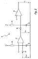
- the frequency detection stage 18 serving as an undercurrent detector is shown as a detailed circuit example.
- a first capacitor 19 is constantly charged by the operating voltage U B via a first charging resistor 20.
- the capacitor voltage is present at the inverting input of a first operational amplifier 21.
- a fixed comparison voltage U 1 is present at the non-inverting input of the operational amplifier 21.
- the pulse-width modulated voltage signal Upwm at the output of the controller 12 is applied to the capacitor 19 via a first discharge diode 22 such that it can be discharged during the signal pauses of the pulse-width-modulated voltage signal Upwm.
- the second operational amplifier 21 corresponds to a second one built circuit arrangement downstream, the off a second capacitor 23, a second charging resistor 24, a second operational amplifier 25 and a second Discharge diode 26 exists. While on the first circuit arrangement the pulse width modulated voltage signal Upwm is is the output signal Uop1 to the second circuit arrangement of the first operational amplifier 21. The output signal of the second operational amplifier 25 forms that Switching signal Us for the switching stage 16.
- the first capacitor 17 regularly discharged via the first discharge diode 22, so that the output voltage Uop1 of the first operational amplifier 21 high.
- the second discharge diode 24 is thereby blocked, and the second capacitor 23 is through the second charging resistor 24 charged so that the output voltage of the second operational amplifier 25, that is Switching signal Us, becomes zero.
- the pulse-width-modulated voltage signal Upwm no longer has a switching frequency or clocking, but is a continuous signal which is above the comparison voltage U 1 .
- the first discharge diode 22 is thereby blocked, and the first capacitor 19 is charged via the first charging resistor 20 with a certain time constant.
- the first operational amplifier 21 used as a comparator switches over, so that its output signal Uop1 becomes zero.
- the second discharge diode 26 can now discharge the second capacitor 23, so that the second operational amplifier 25 also switches over and the output signal now present as the switching signal Us can switch over to the higher starting current or the higher desired voltage Ua.
- the first circuit arrangement consisting of components 19 to 22 practically acts as a timing element which, after no clocking of the voltage signal Upwm, causes the switchover to the higher starting current only after a time delay t1.
- the second, from the Components 23 to 26 existing circuitry are also eliminated or be replaced by an inverter.
- the frequency detection stage 18 can of course also can be realized digitally, for example by two digital ones Time or delay elements.
- an additional optical and / or acoustic signaling device for reporting a inadmissible undercurrent or to report an interruption the timing of the pulse width modulated voltage signal Upwm be provided.
- This notification device can, for example by the switching signal Us or by the voltage Uop1 turned on at the output of the first operational amplifier 21 become.
Landscapes
- Physics & Mathematics (AREA)
- Electromagnetism (AREA)
- Engineering & Computer Science (AREA)
- Power Engineering (AREA)
- Dc-Dc Converters (AREA)
- Relay Circuits (AREA)
- Control Of Linear Motors (AREA)
Abstract
Description
- Fig. 1
- eine schematische Blockdarstellung der gesamten Schaltungsvorrichtung mit einer Frequenzdetektionsstufe und
- Fig. 2
- eine detaillierte Darstellung der Frequenzdetektionsstufe.
Claims (10)
- Schaltungsvorrichtung zur Erzeugung eines durch eine Magnetspulenanordnung fließenden, durch Taktung geregelten Spulenstroms, mit Umschaltmitteln zur Umschaltung von einem anfänglich höheren Anzugsstrom nach einer vorgebbaren Anzugszeitdauer auf einen niedrigeren Halte- oder Betriebsstrom, dadurch gekennzeichnet, dass eine Frequenzdetektionsstufe (18) zur Überwachung des Stromsteuersignals (Upwm) für die Magnetspulenanordnung (10) und zur Umschaltung auf den höheren Anzugsstrom oder die dem höheren Anzugsstrom zugrunde liegende höhere Spannung bei ausbleibendem Frequenzsignal vorgesehen ist.
- Schaltungsvorrichtung nach Anspruch 1, dadurch gekennzeichnet, dass die Umschaltmittel (16) ein die Umschaltung auf den niedrigeren Halte- oder Betriebsstrom nach einer vorgebbaren Zeitdauer vornehmendes Zeitglied besitzen oder mit diesem verbunden sind..
- Schaltungsvorrichtung nach Anspruch 1 oder 2, dadurch gekennzeichnet, dass der Ausgang der Frequenzdetektionsstufe (18) mit einem Umschalteingang der Umschaltmittel (16) verbunden ist.
- Schaltungsvorrichtung nach einem der vorhergehenden Ansprüche, dadurch gekennzeichnet, dass das überwachte Stromsteuersignal das Steuersignal für eine Treiber- oder Endstufe (13) der Magnetspulenanordnung (10) ist.
- Schaltungsvorrichtung nach einem der vorhergehenden Ansprüche, dadurch gekennzeichnet, dass die Frequenzdetektionsstufe (18) eine die Umschaltung auf den höheren Anzugsstrom oder höhere Anzugsspannung nach einer vorgebbaren Zeitdauer (t1) ab dem Ausbleiben von Frequenzsignalen auslösendes erstes Zeitglied (19 - 22) besitzt.
- Schaltungsvorrichtung nach Anspruch 5, dadurch gekennzeichnet, dass die Frequenzdetektionsstufe (18) ein die Umschaltung auf den niedrigeren Halte- oder Betriebsstrom nach Wiedereinsetzen der Taktung verzögerndes zweites Zeitglied (23 - 26) besitzt.
- Schaltungsvorrichtung nach Anspruch 5 oder 6, dadurch gekennzeichnet, dass das Zeitglied (19 - 22; 23 - 26) aus einem über einen Widerstand (20; 24) aufladbaren und durch das Frequenzsignal (Upwm) über eine Diode (22; 26) entladbaren Kondensator (19; 23) besteht, dessen Spannung mit einer Festspannung (U1; U2) mittels eines Vergleichers (21; 25) verglichen wird, wobei im Wesentlichen bei Erreichen der einen Spannung durch die andere Spannung ein Schaltsignal auslösbar ist.
- Schaltungsvorrichtung nach Anspruch 7, dadurch gekennzeichnet, dass der Vergleicher (21; 25) als Verstärker, insbesondere Operationsverstärker ausgebildet ist.
- Schaltungsvorrichtung nach Anspruch 5 oder 6, dadurch gekennzeichnet, dass das Zeitglied als digitales Zeitglied ausgebildet ist.
- Schaltungsvorrichtung nach einem der vorhergehenden Ansprüche, dadurch gekennzeichnet, dass eine optische und/oder akustische Meldevorrichtung zur Meldung eines Aussetzens der Taktung vorgesehen ist.
Applications Claiming Priority (2)
| Application Number | Priority Date | Filing Date | Title |
|---|---|---|---|
| DE10302988A DE10302988B3 (de) | 2003-01-25 | 2003-01-25 | Schaltungsvorrichtung zur Erzeugung eines durch eine Magnetspulenanordnung fließenden, durch Taktung geregelten Spulenstroms |
| DE10302988 | 2003-01-25 |
Publications (2)
| Publication Number | Publication Date |
|---|---|
| EP1441371A2 true EP1441371A2 (de) | 2004-07-28 |
| EP1441371A3 EP1441371A3 (de) | 2005-03-23 |
Family
ID=32520117
Family Applications (1)
| Application Number | Title | Priority Date | Filing Date |
|---|---|---|---|
| EP03028815A Withdrawn EP1441371A3 (de) | 2003-01-25 | 2003-12-15 | Schaltungsvorrichtung zur Erzeugung eines durch eine Magnetspulenanordnung fliessenden, durch Taktung geregelten Spulenstroms. |
Country Status (3)
| Country | Link |
|---|---|
| US (1) | US20040145851A1 (de) |
| EP (1) | EP1441371A3 (de) |
| DE (1) | DE10302988B3 (de) |
Families Citing this family (2)
| Publication number | Priority date | Publication date | Assignee | Title |
|---|---|---|---|---|
| JP4692813B2 (ja) | 2005-05-13 | 2011-06-01 | Smc株式会社 | 電磁弁駆動制御装置 |
| CN112292553B (zh) * | 2019-11-05 | 2022-10-28 | 深圳市大疆创新科技有限公司 | 电磁阀控制方法、农业无人飞行器及电磁阀控制设备 |
Family Cites Families (13)
| Publication number | Priority date | Publication date | Assignee | Title |
|---|---|---|---|---|
| JPS59228703A (ja) * | 1983-06-10 | 1984-12-22 | Hitachi Constr Mach Co Ltd | 比例ソレノイドを備えた電磁装置の駆動回路 |
| DE3543055C1 (de) * | 1985-12-05 | 1986-12-11 | Meyer, Hans-Wilhelm, Dr., 2000 Hamburg | Schaltungsanordnung zum Ansteuern eines Elektromagneten |
| US4970622A (en) * | 1986-12-03 | 1990-11-13 | Buechl Josef | Method and apparatus for controlling the operation of an electromagnet |
| US5196983A (en) * | 1991-10-07 | 1993-03-23 | Eastman Kodak Company | Solenoid engagement sensing circuit |
| US5510951A (en) * | 1994-08-01 | 1996-04-23 | Eaton Corporation | Electronic control for 3-wire DC coils |
| DE19529433A1 (de) * | 1995-08-10 | 1997-02-13 | Teves Gmbh Alfred | Verfahren und Schaltungsanordnung zur Überwachung einer Steuerschaltung |
| DE29600866U1 (de) * | 1996-01-19 | 1996-03-07 | Festo Kg, 73734 Esslingen | Schaltungsanordnung zur Steuerung von Magnetventilen |
| US5668693A (en) * | 1996-06-25 | 1997-09-16 | Eaton Corporation | Method of monitoring a contactor |
| DE29715925U1 (de) * | 1997-09-05 | 1997-10-23 | Festo AG & Co, 73734 Esslingen | Schaltungsvorrichtung |
| DE19742038A1 (de) * | 1997-09-24 | 1999-03-25 | Wabco Gmbh | Verfahren zur Zustandserkennung bei einem Magnetventil |
| US6121849A (en) * | 1998-07-24 | 2000-09-19 | Motorola Inc. | Oscillator amplifier with frequency based digital multi-discrete-level gain control and method of operation |
| DE19939650C2 (de) * | 1999-08-13 | 2001-08-02 | Siemens Ag | Schaltungsanordnung zum Betrieb eines Relais |
| EP1209793A1 (de) * | 2000-11-23 | 2002-05-29 | Semiconductor Components Industries LLC | Verfahren und Gerät zur Steuerung einer Stromversorgungseinrichtung |
-
2003
- 2003-01-25 DE DE10302988A patent/DE10302988B3/de not_active Expired - Fee Related
- 2003-12-15 EP EP03028815A patent/EP1441371A3/de not_active Withdrawn
-
2004
- 2004-01-13 US US10/756,619 patent/US20040145851A1/en not_active Abandoned
Also Published As
| Publication number | Publication date |
|---|---|
| US20040145851A1 (en) | 2004-07-29 |
| EP1441371A3 (de) | 2005-03-23 |
| DE10302988B3 (de) | 2004-10-28 |
Similar Documents
| Publication | Publication Date | Title |
|---|---|---|
| DE10210920B4 (de) | Leistungsschalter mit elektronischem Auslöser | |
| DE2751743C2 (de) | Verfahren und Regeleinrichtung zum Zumessen strömender Medien | |
| DE69406407T2 (de) | Schaltungskreis zum Laden von wiederaufladbaren Batterien | |
| DE69914054T2 (de) | Standardeinrichtung zur Steuerung eines Elektromagneten zum Öffnen oder Schliessen eines Schutzschalters | |
| DE3543055C1 (de) | Schaltungsanordnung zum Ansteuern eines Elektromagneten | |
| DE4136415C2 (de) | Verfahren und Vorrichtung zum Prüfen des Betriebs eiens Elektromagneten | |
| EP0837479B1 (de) | Elektromagnettreiberschaltung | |
| EP1403885A2 (de) | Ansteuereinrichtung für eine Magnetspule | |
| DE69914053T2 (de) | Einrichtung zur Steuerung eines Elektromagneten, mit Erfassung von unbeabsichtigtem Bewegen des beweglichen Kerns eines Elektromagneten | |
| DE69216370T2 (de) | Auslösesteuervorrichtung für einen Schalter | |
| EP2546852B1 (de) | Bistabiles Sicherheitsrelais | |
| DE3204234C2 (de) | Schaltungsanordnung zur Steuerung eines Relais | |
| EP0986173B1 (de) | Schaltungsanordnung zur Flankensteilheitsformung | |
| EP0575792B1 (de) | Verfahren und Vorrichtung zur Ansteuerung eines elektromagnetischen Schalters | |
| DE102009006372B4 (de) | Schaltnetzteil mit Schaltkreisen | |
| WO1998043334A1 (de) | Elektronische sicherung | |
| DE10302988B3 (de) | Schaltungsvorrichtung zur Erzeugung eines durch eine Magnetspulenanordnung fließenden, durch Taktung geregelten Spulenstroms | |
| DE102008023198A1 (de) | Hydraulikventilsteuergerät und Verfahren zum Überprüfen eines Hydraulikventilsteuergeräts | |
| DE102004026030B4 (de) | Augabeschaltung mit einer Überstromschutzfunktion | |
| EP4167457A1 (de) | Verfahren und schaltungsanordnung zur regelung eines schaltnetzteils | |
| DE10134346B4 (de) | Vorrichtung zur Ansteuerung eines Elektromagneten | |
| DE69818311T2 (de) | Festkörperüberstromrelais | |
| EP0780950A2 (de) | Verfahren zum Schutz eines Schaltreglers sowie Anordnung und Anwendung | |
| EP1109177B1 (de) | Verfahren zum Schalten einer Last | |
| BE1031305B1 (de) | Schaltgerät zum elektrischen Ein- und Ausschalten einer mit einer Gleichspannungs-Versorgungseinrichtung verbindbaren elektrischen Last sowie Verfahren zum Betreiben eines solchen Schaltgeräts |
Legal Events
| Date | Code | Title | Description |
|---|---|---|---|
| PUAI | Public reference made under article 153(3) epc to a published international application that has entered the european phase |
Free format text: ORIGINAL CODE: 0009012 |
|
| AK | Designated contracting states |
Kind code of ref document: A2 Designated state(s): AT BE BG CH CY CZ DE DK EE ES FI FR GB GR HU IE IT LI LU MC NL PT RO SE SI SK TR |
|
| AX | Request for extension of the european patent |
Extension state: AL LT LV MK |
|
| PUAL | Search report despatched |
Free format text: ORIGINAL CODE: 0009013 |
|
| AK | Designated contracting states |
Kind code of ref document: A3 Designated state(s): AT BE BG CH CY CZ DE DK EE ES FI FR GB GR HU IE IT LI LU MC NL PT RO SE SI SK TR |
|
| AX | Request for extension of the european patent |
Extension state: AL LT LV MK |
|
| 17P | Request for examination filed |
Effective date: 20050318 |
|
| AKX | Designation fees paid |
Designated state(s): AT BE BG CH CY CZ DE DK EE ES FI FR GB GR HU IE IT LI LU MC NL PT RO SE SI SK TR |
|
| RAP1 | Party data changed (applicant data changed or rights of an application transferred) |
Owner name: FESTO AG & CO. KG |
|
| 17Q | First examination report despatched |
Effective date: 20100310 |
|
| STAA | Information on the status of an ep patent application or granted ep patent |
Free format text: STATUS: THE APPLICATION IS DEEMED TO BE WITHDRAWN |
|
| 18D | Application deemed to be withdrawn |
Effective date: 20100721 |