EP1441099B1 - Braking and damping device, in particular for moving furniture parts - Google Patents
Braking and damping device, in particular for moving furniture parts Download PDFInfo
- Publication number
- EP1441099B1 EP1441099B1 EP04000122A EP04000122A EP1441099B1 EP 1441099 B1 EP1441099 B1 EP 1441099B1 EP 04000122 A EP04000122 A EP 04000122A EP 04000122 A EP04000122 A EP 04000122A EP 1441099 B1 EP1441099 B1 EP 1441099B1
- Authority
- EP
- European Patent Office
- Prior art keywords
- braking
- speed
- movement
- pinion
- furniture parts
- Prior art date
- Legal status (The legal status is an assumption and is not a legal conclusion. Google has not performed a legal analysis and makes no representation as to the accuracy of the status listed.)
- Expired - Lifetime
Links
- 238000013016 damping Methods 0.000 title claims abstract description 41
- 230000033001 locomotion Effects 0.000 claims abstract description 60
- 230000000694 effects Effects 0.000 claims description 12
- 230000002093 peripheral effect Effects 0.000 claims description 8
- 238000006073 displacement reaction Methods 0.000 claims description 4
- 239000007788 liquid Substances 0.000 claims description 4
- 230000001360 synchronised effect Effects 0.000 claims description 2
- 238000003780 insertion Methods 0.000 description 4
- 230000037431 insertion Effects 0.000 description 4
- 238000000034 method Methods 0.000 description 3
- 230000008569 process Effects 0.000 description 3
- 210000001520 comb Anatomy 0.000 description 2
- 230000008878 coupling Effects 0.000 description 2
- 238000010168 coupling process Methods 0.000 description 2
- 238000005859 coupling reaction Methods 0.000 description 2
- 230000009471 action Effects 0.000 description 1
- 230000005540 biological transmission Effects 0.000 description 1
- 230000008859 change Effects 0.000 description 1
- 238000011161 development Methods 0.000 description 1
- 230000018109 developmental process Effects 0.000 description 1
- 230000000717 retained effect Effects 0.000 description 1
- 238000010025 steaming Methods 0.000 description 1
Images


Classifications
-
- F—MECHANICAL ENGINEERING; LIGHTING; HEATING; WEAPONS; BLASTING
- F16—ENGINEERING ELEMENTS AND UNITS; GENERAL MEASURES FOR PRODUCING AND MAINTAINING EFFECTIVE FUNCTIONING OF MACHINES OR INSTALLATIONS; THERMAL INSULATION IN GENERAL
- F16F—SPRINGS; SHOCK-ABSORBERS; MEANS FOR DAMPING VIBRATION
- F16F9/00—Springs, vibration-dampers, shock-absorbers, or similarly-constructed movement-dampers using a fluid or the equivalent as damping medium
- F16F9/10—Springs, vibration-dampers, shock-absorbers, or similarly-constructed movement-dampers using a fluid or the equivalent as damping medium using liquid only; using a fluid of which the nature is immaterial
- F16F9/12—Devices with one or more rotary vanes turning in the fluid any throttling effect being immaterial, i.e. damping by viscous shear effect only
- F16F9/125—Devices with one or more rotary vanes turning in the fluid any throttling effect being immaterial, i.e. damping by viscous shear effect only characterised by adjustment means
-
- E—FIXED CONSTRUCTIONS
- E05—LOCKS; KEYS; WINDOW OR DOOR FITTINGS; SAFES
- E05F—DEVICES FOR MOVING WINGS INTO OPEN OR CLOSED POSITION; CHECKS FOR WINGS; WING FITTINGS NOT OTHERWISE PROVIDED FOR, CONCERNED WITH THE FUNCTIONING OF THE WING
- E05F5/00—Braking devices, e.g. checks; Stops; Buffers
- E05F5/02—Braking devices, e.g. checks; Stops; Buffers specially for preventing the slamming of swinging wings during final closing movement, e.g. jamb stops
-
- E—FIXED CONSTRUCTIONS
- E05—LOCKS; KEYS; WINDOW OR DOOR FITTINGS; SAFES
- E05Y—INDEXING SCHEME RELATING TO HINGES OR OTHER SUSPENSION DEVICES FOR DOORS, WINDOWS OR WINGS AND DEVICES FOR MOVING WINGS INTO OPEN OR CLOSED POSITION, CHECKS FOR WINGS AND WING FITTINGS NOT OTHERWISE PROVIDED FOR, CONCERNED WITH THE FUNCTIONING OF THE WING
- E05Y2201/00—Constructional elements; Accessories therefore
- E05Y2201/20—Brakes; Disengaging means, e.g. clutches; Holders, e.g. locks; Stops; Accessories therefore
- E05Y2201/21—Brakes
-
- E—FIXED CONSTRUCTIONS
- E05—LOCKS; KEYS; WINDOW OR DOOR FITTINGS; SAFES
- E05Y—INDEXING SCHEME RELATING TO HINGES OR OTHER SUSPENSION DEVICES FOR DOORS, WINDOWS OR WINGS AND DEVICES FOR MOVING WINGS INTO OPEN OR CLOSED POSITION, CHECKS FOR WINGS AND WING FITTINGS NOT OTHERWISE PROVIDED FOR, CONCERNED WITH THE FUNCTIONING OF THE WING
- E05Y2201/00—Constructional elements; Accessories therefore
- E05Y2201/20—Brakes; Disengaging means, e.g. clutches; Holders, e.g. locks; Stops; Accessories therefore
- E05Y2201/252—Brakes; Disengaging means, e.g. clutches; Holders, e.g. locks; Stops; Accessories therefore characterised by type of friction
- E05Y2201/254—Fluid or viscous friction
-
- E—FIXED CONSTRUCTIONS
- E05—LOCKS; KEYS; WINDOW OR DOOR FITTINGS; SAFES
- E05Y—INDEXING SCHEME RELATING TO HINGES OR OTHER SUSPENSION DEVICES FOR DOORS, WINDOWS OR WINGS AND DEVICES FOR MOVING WINGS INTO OPEN OR CLOSED POSITION, CHECKS FOR WINGS AND WING FITTINGS NOT OTHERWISE PROVIDED FOR, CONCERNED WITH THE FUNCTIONING OF THE WING
- E05Y2201/00—Constructional elements; Accessories therefore
- E05Y2201/20—Brakes; Disengaging means, e.g. clutches; Holders, e.g. locks; Stops; Accessories therefore
- E05Y2201/262—Brakes; Disengaging means, e.g. clutches; Holders, e.g. locks; Stops; Accessories therefore characterised by type of motion
- E05Y2201/266—Brakes; Disengaging means, e.g. clutches; Holders, e.g. locks; Stops; Accessories therefore characterised by type of motion rotary
-
- E—FIXED CONSTRUCTIONS
- E05—LOCKS; KEYS; WINDOW OR DOOR FITTINGS; SAFES
- E05Y—INDEXING SCHEME RELATING TO HINGES OR OTHER SUSPENSION DEVICES FOR DOORS, WINDOWS OR WINGS AND DEVICES FOR MOVING WINGS INTO OPEN OR CLOSED POSITION, CHECKS FOR WINGS AND WING FITTINGS NOT OTHERWISE PROVIDED FOR, CONCERNED WITH THE FUNCTIONING OF THE WING
- E05Y2201/00—Constructional elements; Accessories therefore
- E05Y2201/60—Suspension or transmission members; Accessories therefore
- E05Y2201/622—Suspension or transmission members elements
- E05Y2201/71—Toothed gearing
- E05Y2201/716—Pinions
-
- E—FIXED CONSTRUCTIONS
- E05—LOCKS; KEYS; WINDOW OR DOOR FITTINGS; SAFES
- E05Y—INDEXING SCHEME RELATING TO HINGES OR OTHER SUSPENSION DEVICES FOR DOORS, WINDOWS OR WINGS AND DEVICES FOR MOVING WINGS INTO OPEN OR CLOSED POSITION, CHECKS FOR WINGS AND WING FITTINGS NOT OTHERWISE PROVIDED FOR, CONCERNED WITH THE FUNCTIONING OF THE WING
- E05Y2201/00—Constructional elements; Accessories therefore
- E05Y2201/60—Suspension or transmission members; Accessories therefore
- E05Y2201/622—Suspension or transmission members elements
- E05Y2201/71—Toothed gearing
- E05Y2201/722—Racks
-
- E—FIXED CONSTRUCTIONS
- E05—LOCKS; KEYS; WINDOW OR DOOR FITTINGS; SAFES
- E05Y—INDEXING SCHEME RELATING TO HINGES OR OTHER SUSPENSION DEVICES FOR DOORS, WINDOWS OR WINGS AND DEVICES FOR MOVING WINGS INTO OPEN OR CLOSED POSITION, CHECKS FOR WINGS AND WING FITTINGS NOT OTHERWISE PROVIDED FOR, CONCERNED WITH THE FUNCTIONING OF THE WING
- E05Y2900/00—Application of doors, windows, wings or fittings thereof
- E05Y2900/20—Application of doors, windows, wings or fittings thereof for furnitures, e.g. cabinets
Definitions
- the invention relates to a braking and damping device for moving masses, in particular for movable furniture parts, such.
- DE 101 21 977 A1 describes a brake and damping device for a furniture fitting, in particular applied here in a furniture hinge.
- This device dampens the hinge rotation and thus prevents a fast, noisy and the furniture possibly damaging slamming a furniture door, flap or the like.
- the braking and damping effect is effected by at least one linearly movable slide, which has at least one sliding surface which slides along an associated, fixed sliding surface of the furniture fitting, wherein between the sliding surfaces a highly viscous, liquid medium is introduced, which generates this brake damping effect ,
- the movable part of the furniture fitting such.
- the slider As a hinge arm, engages only in the range of a closing angle in the slider, so that the brake-damping effect also acts only within this closing angle. However, during the opening movement, the slider must also overcome the entire braking force through the opening angle range until the hinge arm disengages and can be brought into the open position when idling.
- the essence of the invention is that the brake elements are coupled to each other via a force and wegübertragendes element, such that in a first phase of movement, the brake elements perform a synchronous movement in which the relative speed between the active surfaces is smaller than the speed of the first coupled with the furniture part braking element, that in a second phase of movement, the brake elements perform an opposite movement, in which the relative speed between the active surfaces is greater than the speed of the first, coupled to the furniture part braking element, and that in a third, the first two phases of movement opposite Movement phase in which the second brake element is substantially stationary, the relative speed between the active surfaces substantially corresponds to the speed of the first, coupled to the furniture part braking element.
- the first two phases of movement are preferably carried out during braking of the movable furniture part, ie during a first direction of movement of the movable furniture part. Due to the different speeds of the active surfaces relative to one another during the first two phases of motion, a different braking force is also achieved.
- the braking force in the first movement phase ie at the beginning of the deceleration process, is lower than the braking force in the second movement phase at the end of the deceleration process.
- the third phase of movement corresponds to the direction of movement that is passed through when resetting or opening the movable furniture part.
- the braking force is substantially lower than in the second movement phase, since the relative speed between the active surfaces of the two brake elements is lower.
- the force and wegübertragende element is a pinion whose axis of rotation is mounted axially and longitudinally movable in longitudinal slots of the housing, which are arranged parallel to the direction of movement of the brake elements.
- each brake element is provided with a rack, wherein both racks cooperate with the pinion and allow a force and displacement transmission between the brake elements.
- the peripheral speed of the pinion during the first phase of motion is lower, preferably substantially lower than the speed of the coupled with the furniture part braking element, wherein the axis of rotation of the pinion along the longitudinal slots moves in the same direction as this brake element.
- the peripheral speed of the pinion substantially corresponds to the speed of the braking element coupled to the furniture part, wherein the axis of rotation of the pinion does not change its position.
- the relative speed between the active surfaces doubles in comparison to the speed of the first, coupled with the furniture part braking element.
- the braking force increases sharply. This high braking and damping effect is retained until the complete insertion position of the movable furniture part.
- the peripheral speed of the pinion substantially corresponds to the speed of the brake element coupled to the furniture part, wherein the axis of rotation of the pinion moves along the longitudinal slots in the same direction as this brake element. This results in a low relative speed between the active surfaces of the brake elements and thus also a lower braking effect.
- the first movement phase corresponds to a first braking force
- the second movement phase to a second braking force
- the third movement phase corresponds to a third braking force.
- An increase in the braking effect and a homogeneous braking behavior can advantageously be achieved by introducing a highly viscous liquid between the active surfaces.
- the active surface of the respective braking element is preferably formed by a comb-groove region.
- the length of the braking portion is also determined by the effective length of the ridge groove portion of the first brake member and the effective length of the ridge groove portion of the second brake member, which are different from each other.
- the three phases of motion can be traversed in reverse order, i. the actual braking and damping process extends over the third movement phase, while during the return movement of the device, the second and the first movement phase are successively passed.
- Figure 1 shows the brake and damping device 1 in the fully extended position, ie at the beginning of their braking-damping effect, eg when closing a drawer.
- a housing 2 preferably as a pipe with a square or rectangular cross-section is formed, two slides, a lower slide 7 and an upper slide 12, respectively.
- the slides 7, 12 are longitudinally guided in the housing 2 and can therein in the direction of arrows 19 and 20 (Fig. 5) move back and forth.
- One end of the housing 2 is provided with a cover 5, which may preferably also be designed for fastening the device.
- this cover 5 is preferably a vent hole 6.
- the opposite end of the housing 2 is open, only a stop 18 is provided at this end (see also Figure 9).
- the lower slide 7 comprises a push and pull rod 8 with a coupling head, which projects from the open end of the housing 2.
- the coupling head is connected to the movable furniture part (not shown) to be braked.
- the push and pull rod 8 is followed by a rack member 9 and a comb-Nuten Siemens 10 at.
- the comb groove portion 10 forms the actual effective surface 11 for generating a braking force.
- the horizontal surfaces of the slide 7, 12, and the vertical side surfaces are longitudinally displaceable with sliding seat in the housing 2.
- the upper slide 12 is designed without push and pull rod and therefore shorter and has an approximately equal length of rack member 13 as the lower slide, but a shorter comb groove portion 14.
- This comb-benefit region 14 forms an active surface 15 for generating a braking force.
- the slider 12 is also mounted longitudinally displaceable with sliding fit in the housing 2. Both slides 7, 12 are guided facing each other, so that the comb-groove portions 10, 14 can also engage with sliding fit into each other. Also, both rack portions 9, 13 are directed against each other, so that a pinion 16 located therebetween forms a torque-transmitting pinion.
- the pinion 16 has a continuous axis 17 which is mounted on both sides in longitudinal slots 3, 4 of the housing 2 axially and longitudinally movable.
- a highly viscous liquid is preferably introduced.
- the push and pull rod 8 of the slide 7 is already moved a little way into the housing 2.
- the pinion 16 moves in a clockwise direction and its axis 17 is simultaneously taken along the longitudinal slots 3, 4 in the direction 19.
- the peripheral speed of the pinion 16 is therefore smaller than the speed of the lower slider 7.
- the pinion 16 and the upper slide 12 are approximately at its half displacement. Due to the lower peripheral speed of the pinion 16, the upper slide 12 has covered only about 1 ⁇ 4 of the displacement of the lower slide 7 and indeed in the same direction (arrow 19).
- the relative speed between the active surfaces 11, 15 of the comb and groove portions 10, 14 is therefore only about half as large as the insertion speed of the push and pull rod 8, d. H. the speed of the furniture part to be braked.
- the damping effect is therefore relatively low in this first movement phase.
- Figure 5 shows the lower slide 7 at its Wegde.
- the upper slide 12 has also covered his work path and is a little way in front of his stop 18th
- FIG. 6 shows the beginning of the third movement phase of the brake and damping device 1.
- the two slides 7, 12 are returned to their initial position.
- the push and pull rod 8 of the lower slide 7 is already pulled out in the direction of arrow 20 a piece of the housing 2.
- the pinion 16 rotates counterclockwise and has already unrolled on the rack 13 of the upper slider 12 and the slider is fully pressed against the stop 18.
- the upper slide 12 thus remains for the rest of the third movement phase.
- the lower slide 7 and the pinion 16 maintain their extension movement, wherein the pinion forcibly in the direction of arrow 20 along the longitudinal slots 3, 4 moves.
- the comb and groove regions 10, 14 or the active surfaces 11, 15 move toward one another at a speed which corresponds to the pull-out speed of the lower slide 7.
- the braking effect achieved is not so great and is between the braking forces of the first two phases of motion.
- the braking force is substantially constant throughout the third movement phase. This movement is maintained beyond the position shown in FIG.
Abstract
Description
Die Erfindung betrifft eine Brems- und Dämpfungsvorrichtung für bewegliche Massen, insbesondere für bewegliche Möbelteile, wie z.B. Schubladen, Möbeltüren und Klappen, nach dem Oberbegriff des Patentanspruchs 1.The invention relates to a braking and damping device for moving masses, in particular for movable furniture parts, such. Drawers, furniture doors and flaps, according to the preamble of patent claim 1.
Derartige, im wesentlichen auf dem Reibungsprinzip beruhende Brems- und Dämpfungsvorrichtungen sind bekannt.
Die DE 101 21 977 A1 beschreibt eine Brems- und Dämpfvorrichtung für einen Möbelbeschlag, hier insbesondere angewendet in einem Möbelscharnier. Diese Vorrichtung dämpft die Scharnierdrehbewegung und verhindert damit ein schnelles, geräuschvolles und das Möbelstück möglicherweise beschädigendes Zuschlagen einer Möbeltüre, Klappe oder ähnliches. Die Brems- und Dämpfungswirkung wird durch mindestens einen linear bewegbaren Schieber bewirkt, welcher mindestens eine Gleitfläche aufweist, die an einer zugeordneten, feststehenden Gleitfläche des Möbelbeschlages entlang gleitet, wobei zwischen den Gleitflächen ein hochviskoses, flüssiges Medium eingebracht ist, welches diese Brems-Dämpfwirkung erzeugt. Der bewegliche Teil des Möbelbeschlags, wie z. B. ein Scharnierarm, kuppelt sich nur im Bereich eines Schließwinkels in den Schieber ein, so dass die Brems-Dämpfwirkung auch nur innerhalb dieses Schließwinkels wirkt. Der Schieber muss aber bei der Öffnungsbewegung aber auch die gesamte Bremskraft durch den Öffnungswinkelbereich überwinden, bis der Scharnierarm auskuppelt und im Leerlauf in die Offenstellung gebracht werden kann.Such, based essentially on the friction principle braking and damping devices are known.
DE 101 21 977 A1 describes a brake and damping device for a furniture fitting, in particular applied here in a furniture hinge. This device dampens the hinge rotation and thus prevents a fast, noisy and the furniture possibly damaging slamming a furniture door, flap or the like. The braking and damping effect is effected by at least one linearly movable slide, which has at least one sliding surface which slides along an associated, fixed sliding surface of the furniture fitting, wherein between the sliding surfaces a highly viscous, liquid medium is introduced, which generates this brake damping effect , The movable part of the furniture fitting, such. As a hinge arm, engages only in the range of a closing angle in the slider, so that the brake-damping effect also acts only within this closing angle. However, during the opening movement, the slider must also overcome the entire braking force through the opening angle range until the hinge arm disengages and can be brought into the open position when idling.
Es ist Aufgabe der Erfindung, eine Brems- und Dämpfungsvorrichtung, insbesondere für bewegliche Möbelteile zu schaffen, welche die Bewegung des Möbelteils wirksam abbremst und dämpft, deren Brems- und Dämpfungsverhalten sich in der einen Bewegungsrichtung aber wesentlich von dem Brems- und Dämpfungsverhalten in der anderen Richtung unterscheidet.It is an object of the invention to provide a braking and damping device, in particular for moving furniture parts, which effectively slows down and dampens the movement of the furniture part, the braking and damping behavior in one direction of movement but substantially from the braking and damping behavior in the other Direction is different.
Diese Aufgabe wird erfindungsgemäß durch die im Patentanspruch 1 angegebenen Merkmale gelöst.This object is achieved by the features specified in claim 1.
Das Wesen der Erfindung besteht darin, dass die Bremselemente über ein kraft- und wegübertragendes Element miteinander gekoppelt sind, derart, dass in einer ersten Bewegungsphase die Bremselemente eine gleichläufige Bewegung ausführen, bei der die Relativgeschwindigkeit zwischen den Wirkflächen kleiner ist als die Geschwindigkeit des ersten, mit dem Möbelteil gekoppelten Bremselements, dass in einer zweiten Bewegungsphase die Bremselemente eine gegenläufige Bewegung ausführen, bei der die Relativgeschwindigkeit zwischen den Wirkflächen größer ist als die Geschwindigkeit des ersten, mit dem Möbelteil gekoppelten Bremselements, und dass in einer dritten, den ersten beiden Bewegungsphasen entgegengesetzten Bewegungsphase, bei der das zweite Bremselement im wesentlichen stillsteht, die Relativgeschwindigkeit zwischen den Wirkflächen im wesentlichen der Geschwindigkeit des ersten, mit dem Möbelteil gekoppelten Bremselements entspricht.The essence of the invention is that the brake elements are coupled to each other via a force and wegübertragendes element, such that in a first phase of movement, the brake elements perform a synchronous movement in which the relative speed between the active surfaces is smaller than the speed of the first coupled with the furniture part braking element, that in a second phase of movement, the brake elements perform an opposite movement, in which the relative speed between the active surfaces is greater than the speed of the first, coupled to the furniture part braking element, and that in a third, the first two phases of movement opposite Movement phase in which the second brake element is substantially stationary, the relative speed between the active surfaces substantially corresponds to the speed of the first, coupled to the furniture part braking element.
Die ersten beiden Bewegungsphasen werden vorzugsweise beim Abbremsen des beweglichen Möbelteils, d.h. während einer ersten Bewegungsrichtung des beweglichen Möbelteils durchlaufen. Durch die sich während der ersten beiden Bewegungsphasen unterscheidenden Geschwindigkeiten der Wirkflächen relativ zueinander wird auch einer unterschiedliche Bremskraft erreicht. Vorzugsweise ist die Bremskraft in der ersten Bewegungsphase, also am Anfang des Abbremsvorgangs, geringer als die Bremskraft in der zweiten Bewegungsphase am Ende des Abbremsvorgangs.
Die dritte Bewegungsphase entspricht der Bewegungsrichtung, die bei einem Rückstellen oder Öffnen des beweglichen Möbelteils durchlaufen wird. Hierbei ist die Bremskraft wesentlich geringer als in der zweiten Bewegungsphase, da auch die Relativgeschwindigkeit zwischen den Wirkflächen der beiden Bremselemente geringer ist.The first two phases of movement are preferably carried out during braking of the movable furniture part, ie during a first direction of movement of the movable furniture part. Due to the different speeds of the active surfaces relative to one another during the first two phases of motion, a different braking force is also achieved. Preferably, the braking force in the first movement phase, ie at the beginning of the deceleration process, is lower than the braking force in the second movement phase at the end of the deceleration process.
The third phase of movement corresponds to the direction of movement that is passed through when resetting or opening the movable furniture part. Here, the braking force is substantially lower than in the second movement phase, since the relative speed between the active surfaces of the two brake elements is lower.
Bevorzugte Ausgestaltungen und Weiterbildungen der Erfindung sind in den Unteransprüchen angegeben.Preferred embodiments and further developments of the invention are specified in the subclaims.
In einer bevorzugten Ausgestaltung der Erfindung ist das kraft- und wegübertragende Element ein Zahnritzel, dessen Drehachse axial- und längsbeweglich in Längsschlitzen des Gehäuses gelagert ist, die parallel zur Bewegungsrichtung der Bremselemente angeordnet sind. Ferner ist jedes Bremselement mit einer Zahnstange versehen, wobei beide Zahnstangen mit dem Zahnritzel zusammenwirken und eine kraft- und Wegübertragung zwischen den Bremselementen erlauben.In a preferred embodiment of the invention, the force and wegübertragende element is a pinion whose axis of rotation is mounted axially and longitudinally movable in longitudinal slots of the housing, which are arranged parallel to the direction of movement of the brake elements. Further, each brake element is provided with a rack, wherein both racks cooperate with the pinion and allow a force and displacement transmission between the brake elements.
Gemäß der vorteilhaften Ausgestaltung der Erfindung ist die Umfangsgeschwindigkeit des Zahnritzels während der ersten Bewegungsphase geringer, vorzugsweise wesentlich geringer, als die Geschwindigkeit des mit dem Möbelteil gekoppelten Bremselements, wobei sich die Drehachse des Zahnritzels entlang der Längsschlitze in der selben Richtung wie dieses Bremselement bewegt. Somit kann erreicht werden, dass die Relativgeschwindigkeit zwischen den Wirkflächen nur etwa halb so groß ist wie die Geschwindigkeit des ersten, mit dem Möbelteil gekoppelten Bremselements.According to the advantageous embodiment of the invention, the peripheral speed of the pinion during the first phase of motion is lower, preferably substantially lower than the speed of the coupled with the furniture part braking element, wherein the axis of rotation of the pinion along the longitudinal slots moves in the same direction as this brake element. Thus, it can be achieved that the relative speed between the active surfaces is only about half as great as the speed of the first braking element coupled to the furniture part.
Während der zweiten Bewegungsphase entspricht die Umfangsgeschwindigkeit des Zahnritzels im wesentlichen der Geschwindigkeit des mit dem Möbelteil gekoppelten Bremselements, wobei die Drehachse des Zahnritzels ihre Position nicht verändert. In diese Phase verdoppelt sich die Relativgeschwindigkeit zwischen den Wirkflächen im Vergleich zur Geschwindigkeit des ersten, mit dem Möbelteil gekoppelten Bremselements. Die Bremskraft steigt stark an. Dieser hohe Brems- und Dämpfungseffekt bleibt bis zur vollkommenen Einschiebestellung des beweglichen Möbelteils erhalten.During the second phase of movement, the peripheral speed of the pinion substantially corresponds to the speed of the braking element coupled to the furniture part, wherein the axis of rotation of the pinion does not change its position. In this phase, the relative speed between the active surfaces doubles in comparison to the speed of the first, coupled with the furniture part braking element. The braking force increases sharply. This high braking and damping effect is retained until the complete insertion position of the movable furniture part.
Während der dritten Bewegungsphase entspricht die Umfangsgeschwindigkeit des Zahnritzels im wesentlichen der Geschwindigkeit des mit dem Möbelteil gekoppelten Bremselements, wobei sich die Drehachse des Zahnritzels entlang der Längsschlitze in der selben Richtung wie dieses Bremselement bewegt. Somit ergibt sich eine geringe Relativgeschwindigkeit zwischen den Wirkflächen der Bremselemente und damit auch eine geringere Bremswirkung.During the third phase of movement, the peripheral speed of the pinion substantially corresponds to the speed of the brake element coupled to the furniture part, wherein the axis of rotation of the pinion moves along the longitudinal slots in the same direction as this brake element. This results in a low relative speed between the active surfaces of the brake elements and thus also a lower braking effect.
Erfindungsgemäß lässt sich somit vorteilhaft erreichen, dass die erste Bewegungsphase einer ersten Bremskraft, die zweite Bewegungsphase einer zweiten Bremskraft, und die dritte Bewegungsphase einer dritten Bremskraft entspricht. Durch Dimensionierung der effektiven Länge und Oberfläche der Wirkflächen, sowie durch Anpassung der Länge der Längsschlitze lassen sich diese unterschiedlichen Bremskräfte in ihrer Höhe und in ihrem gegenseitigen Verhältnis anpassen. Die Erfindung unterstützt in einfacher Weise auch eine freie Wahl beliebig langer Dämpfbereiche.Thus, according to the invention, it can advantageously be achieved that the first movement phase corresponds to a first braking force, the second movement phase to a second braking force, and the third movement phase corresponds to a third braking force. By dimensioning the effective length and surface of the active surfaces, as well as by adjusting the length of the longitudinal slots, these different braking forces can be adjusted in their height and in their mutual relationship. The invention also supports in a simple manner a free choice of any length steaming areas.
Eine Erhöhung der Bremswirkung und ein homogenes Bremsverhalten kann vorteilhaft dadurch erreicht werden, dass zwischen die Wirkflächen eine hochviskose Flüssigkeit eingebracht ist.An increase in the braking effect and a homogeneous braking behavior can advantageously be achieved by introducing a highly viscous liquid between the active surfaces.
Die Wirkfläche des jeweiligen Bremselements wird vorzugsweise durch einen Kamm-Nutenbereich gebildet. Durch Variation der Anzahl der Kämme und Nuten können die effektiven Reibungskräfte und damit auch die Bremskräfte verändert werden.The active surface of the respective braking element is preferably formed by a comb-groove region. By varying the number of combs and grooves, the effective frictional forces and thus the braking forces can be changed.
Die Länge des Bremsbereiches wird auch durch die wirksame Länge des Kamm-Nutenbereichs des ersten Bremselements und der wirksamen Länge des Kamm-Nutenbereichs des zweiten Bremselements bestimmt, die sich voneinander unterscheiden.The length of the braking portion is also determined by the effective length of the ridge groove portion of the first brake member and the effective length of the ridge groove portion of the second brake member, which are different from each other.
Natürlich ist es vorgesehen, dass die drei Bewegungsphasen in umgekehrter Reihenfolge durchlaufen werden können, d.h. der eigentliche Brems- und Dämpfungsvorgang erstreckt sich über die dritte Bewegungsphase, während bei der Rückstellbewegung der Vorrichtung nacheinander die zweite und die erste Bewegungsphase durchlaufen werden.Of course, it is envisaged that the three phases of motion can be traversed in reverse order, i. the actual braking and damping process extends over the third movement phase, while during the return movement of the device, the second and the first movement phase are successively passed.
Nachfolgend wird die Erfindung anhand der Zeichnungen näher erläutert. Aus den Zeichnungen und deren Beschreibung ergeben sich weitere Merkmale, Vorteile und Anwendungsmöglichkeiten der Erfindung.
- Figur 1 zeigt die Brems- und Dämpfungsvorrichtung in voll ausgezogener Stellung, d. h. am Anfang ihrer Brems-Dämpfwirkung;
Figur 2 zeigt die Brems- und Dämpfungsvorrichtung in einer Stellung, bei der die Schub- und Zugstange ein Stück eingefahren ist;Figur 3 zeigt die Brems- und Dämpfungsvorrichtung in einer Stellung, bei der die Schub- und Zugstange noch weiter eingefahren ist;Figur 4 zeigt die Brems- und Dämpfungsvorrichtung in einer Stellung, bei der die Schub- und Zugstange fast ganz eingefahren ist;Figur 5 zeigt die Brems- und Dämpfungsvorrichtung mit ihrer Schub- und Zugstange am Arbeitswegende;Figur 6 zeigt die Brems- und Dämpfungsvorrichtung in einer Stellung, bei der die Schub- und Zugstange ein Stück ausgezogen ist;Figur 7 zeigt die Brems- und Dämpfungsvorrichtung in einer Stellung, bei der die Schub- und Zugstange fast maximal ausgezogen ist;Figur 8 zeigt die Brems- und Dämpfungsvorrichtung in einer Stellung, bei der die Schub- und Zugstange maximal ausgezogen ist;Figur 9 zeigt die Einzelteile der Brems- und Dämpfungsvorrichtung in einer Explosionsdarstellung.
- Figure 1 shows the brake and damping device in the fully extended position, ie at the beginning of their braking-damping action;
- Figure 2 shows the brake and damping device in a position in which the push and pull rod is retracted a piece;
- Figure 3 shows the brake and damping device in a position in which the push and pull rod is retracted even further;
- Figure 4 shows the brake and damping device in a position in which the push and pull rod is almost completely retracted;
- FIG. 5 shows the brake and damping device with its push and pull rod at the end of the working path;
- Figure 6 shows the braking and damping device in a position in which the push and pull rod is pulled out a piece;
- Figure 7 shows the brake and damping device in a position in which the push and pull rod is almost fully extended;
- Figure 8 shows the brake and damping device in a position in which the push and pull rod is extended to the maximum;
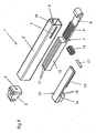
- FIG. 9 shows the individual parts of the braking and damping device in an exploded view.
Figur 1 zeigt die Brems- und Dämpfungsvorrichtung 1 in voll ausgezogener Stellung, d. h. am Anfang ihrer Brems-Dämpfwirkung, z.B. beim Schließen einer Schublade. Wie in Verbindung mit Figur 9 ersichtlich ist, sind in einem Gehäuse 2, das vorzugsweise als Rohr mit einem quadratischen oder rechtwinkligen Querschnitt ausgebildet ist, zwei Schieber, ein unterer Schieber 7 und ein oberer Schieber 12, angeordnet. Die Schieber 7, 12 sind im Gehäuse 2 längsgeführt und können sich darin in den Pfeilrichtungen 19 bzw. 20 (Fig. 5) vor- und zurückbewegen. Ein Ende des Gehäuses 2 ist mit einem Deckel 5 versehen, welcher vorzugsweise auch zur Befestigung der Vorrichtung ausgebildet sein kann. In diesem Deckel 5 befindet sich vorzugsweise eine Entlüftungsbohrung 6. Das gegenüberliegende Ende des Gehäuses 2 ist offen, lediglich ein Anschlag 18 ist an diesem Ende vorgesehen (siehe auch Figur 9).Figure 1 shows the brake and damping device 1 in the fully extended position, ie at the beginning of their braking-damping effect, eg when closing a drawer. As can be seen in connection with Figure 9 are in a
Der untere Schieber 7 umfasst eine Schub- und Zugstange 8 mit einem Kupplungskopf, die aus dem offenen Ende des Gehäuses 2 ragt. Der Kupplungskopf wird mit dem abzubremsenden beweglichen Möbelteil (nicht dargestellt) verbunden. Der Schub- und Zugstange 8 schließen sich ein Zahnstangenteil 9 und einen Kamm-Nutenbereich 10 an. Der Kamm-Nutenbereich 10 bildet die eigentliche Wirkfläche 11 zur Erzeugung einer Bremskraft aus. Die horizontalen Flächen der Schiebers 7, 12, sowie die senkrechten Seitenflächen sind mit Schiebesitz im Gehäuse 2 längsverschiebbar.The
Der obere Schieber 12 ist ohne Schub- und Zugstange und daher kürzer ausgeführt und besitzt ein etwa gleich langes Zahnstangenteil 13 wie der untere Schieber, aber einen kürzeren Kamm-Nutenbereich 14. Auch dieser Kamm-Nutzenbereich 14 bildet eine Wirkfläche 15 zur Erzeugung einer Bremskraft. Der Schieber 12 ist ebenfalls mit Schiebesitz im Gehäuse 2 längsverschiebbar gelagert. Beide Schieber 7, 12 sind einander zugewandt geführt, so dass die Kamm-Nutenbereiche 10, 14 ebenfalls mit Schiebesitz ineinander greifen können. Auch beide Zahnstangenbereiche 9, 13 sind gegeneinander gerichtet, so dass ein sich dazwischen befindliches Zahnritzel 16 einen drehmomentübertragenden Zahntrieb ausbildet. Das Zahnritzel 16 hat eine durchgehende Achse 17, welche auf beiden Seiten in Längsschlitzen 3, 4 des Gehäuses 2 axial- und längsbeweglich gelagert ist.The
In die ineinander greifenden Kämme und Nuten der beiden Schieber 7, 12 bzw. zwischen den Wirkflächen 11, 15 ist vorzugsweise eine hochviskose Flüssigkeit eingebracht.In the intermeshing combs and grooves of the two
In Figur 1 befindet sich der untere Schieber 7 in seiner voll ausgezogenen Stellung, und der obere Schieber ist ein kleines Stück vom Anschlag 18 entfernt. Durch das abzubremsende Möbelteil wird die Schub- und Zugstange nun ein Pfeilrichtung 19 bewegt.In Figure 1, the
In der Figur 2 ist die Schub- und Zugstange 8 des Schiebers 7 bereits ein Stück weit in das Gehäuse 2 eingefahren. Während dieser Bewegung bewegt sich das Zahnritzel 16 im Uhrzeigersinn und dessen Achse 17 wird gleichzeitig entlang der Längsschlitze 3, 4 in Richtung 19 mitgenommen. Die Umfangsgeschwindigkeit des Ritzels 16 ist daher kleiner als die Geschwindigkeit des unteren Schiebers 7. In der gezeigten Stellung befinden sich das Ritzel 16 und der obere Schieber 12 etwa auf ihrem halbem Verschiebeweg. Durch die geringere Umfangsgeschwindigkeit des Ritzels 16 hat der obere Schieber 12 aber nur etwa ¼ des Verschiebeweges des unteren Schiebers 7 zurückgelegt und zwar in der selben Richtung (Pfeilrichtung 19). Die Relativgeschwindigkeit zwischen den Wirkflächen 11, 15 der Kamm- und Nutenbereiche 10, 14 ist daher auch nur etwa halb so groß wie die Einschubgeschwindigkeit der Schub- und Zugstange 8, d. h. die Geschwindigkeit des abzubremsenden Möbelteils. Die Dämpfwirkung ist daher in dieser ersten Bewegungsphase relativ gering.In the figure 2, the push and pull
In der Figur 3 steht die Achse 17 des Ritzels 16 am Ende der Längsschlitze 3, 4 an, während die Schub- und Zugstange 8 mit dem unteren Schieber 7 und der Zahnstange 9 die Einschubbewegung fortsetzt. Das Ritzel 16 dreht sich daher im Uhrzeigersinn mit derselben Geschwindigkeit wie die Geschwindigkeit des unteren Schiebers und zwar an Ort und Stelle am hinteren Ende der Längsschlitze 3, 4. Der obere Schieber 12 wird daher mit derselben Längsgeschwindigkeit wie der untere Schieber 7 in Richtung des Anschlags 18, d.h. entgegen der Pfeilrichtung 19, bewegt. Die Schieber 7, 12 bewegen sich daher zueinander in entgegengesetzter Richtung, so dass sich die Relativgeschwindigkeit zwischen den Kamm- und Nutenbereichen 10, 14 in Bezug auf die jeweiligen Geschwindigkeit der Schieber 7, 12 verdoppelt. Dadurch steigt auch die Brems- und Dämpfungswirkung in dieser zweiten Bewegungsphase stark an. Dieser hohe Brems- und Dämpfungseffekt bleibt bis zur vollkommenen Einschiebestellung des unteren Schiebers 7 erhalten.
In der in Figur 4 gezeigten Stellung des Schiebersystems bewegen sich die Wirkflächen 11, 15 der Kamm- und Nutenbereiche 10, 14 immer noch mit doppelter Relativgeschwindigkeit zueinander.In the figure 3 is the
In the position of the slide system shown in FIG. 4, the
Figur 5 zeigt den unteren Schieber 7 an seinem Arbeitswegende. Der obere Schieber 12 hat seinen Arbeitsweg ebenfalls zurückgelegt und steht ein kleines Stück vor seinem Anschlag 18.Figure 5 shows the
Figur 6 zeigt den Beginn der dritten Bewegungsphase der Brems- und Dämpfungsvorrichtung 1. In dieser Bewegungsphase werden die beiden Schieber 7, 12 wieder in ihre Anfangsstellung gebracht. Die Schub- und Zugstange 8 des unteren Schiebers 7 ist bereits in Pfeilrichtung 20 ein Stück aus dem Gehäuse 2 herausgezogen. Das Ritzel 16 dreht sich gegen den Uhrzeigersinn und hat sich bereits auf der Zahnstange 13 des oberen Schiebers 12 abgerollt und den Schieber ganz an den Anschlag 18 gedrückt. Der obere Schieber 12 bleibt somit für den Rest der dritten Bewegungsphase stehen. Der untere Schieber 7 und das Ritzel 16 behalten ihre Auszugbewegung bei, wobei sich das Ritzel zwangsweise in Pfeilrichtung 20 entlang der Längsschlitze 3, 4 bewegt. Die Kamm- und Nutenbereiche 10, 14 bzw. die Wirkflächen 11, 15 bewegen sich zueinander mit einer Geschwindigkeit, die der Auszugsgeschwindigkeit des unteren Schiebers 7 entspricht. Die dadurch erzielte Bremswirkung ist nicht so groß und liegt zwischen den Bremskräften der ersten beiden Bewegungsphasen. Die Bremskraft ist während der gesamten dritten Bewegungsphase im wesentlichen gleichbleibend. Diese Bewegung wird über die Stellung gemäß Figur 7 hinaus beibehalten.FIG. 6 shows the beginning of the third movement phase of the brake and damping device 1. In this movement phase, the two
Am Ende der dritten Bewegungsphase, d.h. am Ende der Auszugbewegung, wie es in Figur 8 dargestellt ist, schlägt die Achse 17 des Ritzels 16 am Anfang der Längsschlitze 3, 4 an und drückt den oberen Schieber 12 etwas vom Anschlag 18 weg. Die Schub- und Zugstange 8, d.h. der untere Schieber 7, ist am Auszugsende angelangt. Diese Stellungen der Schieber 7, 12 entsprechen den in Figur 1 dargestellten Anfangsstellungen.At the end of the third movement phase, ie at the end of the extension movement, as shown in FIG. 8, the
- 11
- Brems- und DämpfungsvorrichtungBraking and damping device
- 22
- Gehäusecasing
- 33
- Längsschlitzlongitudinal slot
- 44
- Längsschlitzlongitudinal slot
- 55
- Deckelcover
- 66
- Entlüftungsbohrungvent hole
- 77
- Schieber (erster)Slider (first)
- 88th
- Schub-ZugstangePush-pull rod
- 99
- Zahnstangerack
- 1010
- Kamm-Nuten-BereichComb-groove area
- 1111
- Wirkflächeeffective area
- 1212
- Schieber (zweiter)Slider (second)
- 1313
- Zahnstangerack
- 1414
- Kamm-Nuten-BereichComb-groove area
- 1515
- Wirkflächeeffective area
- 1616
- Zahnritzelpinions
- 1717
- Achseaxis
- 1818
- Anschlagattack
- 1919
- Pfeilrichtungarrow
- 2020
- Pfeilrichtungarrow
Claims (11)
- Device for braking and damping movable furniture parts, comprising a housing (2), a first braking element (7) arranged partially in the housing and displaceable therein, which is coupled to the movable furniture part, and a second braking element (12) arranged in the housing and displaceable therein, wherein the braking elements form operative faces (11, 15) facing one another, which generate a braking force relative to one another during a displacement of the braking elements, characterised in that the braking elements (7, 12) are coupled to one another via a force-transmitting and path-transmitting element (16), in such a way that in a first movement phase, the braking elements (7, 12) carry out a synchronous movement, in which the relative speed between the operative faces (11, 15) is less than the speed of the first braking element (7) coupled to the furniture part, and in that in a second movement phase, the braking elements (7, 12) carry out a movement in the opposite direction, in which the relative speed between the operative faces (11, 15) is greater than the speed of the first braking element (7) coupled to the furniture part, and in that a third movement phase counter to the first two movement phases, the second braking element (12) substantially stands still, the relative speed between the operative faces (11, 15) substantially corresponding to the speed of the first braking element (7) coupled to the furniture part.
- Device for braking and damping movable furniture parts according to claim 1, characterised in that the force-transmitting and path-transmitting element is a pinion (16), the rotational axis (17) of which is mounted so as to be axially and longitudinally movable in elongated slots (3, 4) of the housing (2), which are arranged parallel to the movement direction of the braking elements (7, 12).
- Device for braking and damping movable furniture parts according to either of claims 1 or 2, characterised in that each braking element (7, 12) is provided with a toothed rack (8, 13), and the two toothed racks cooperate with the pinion (16).
- Device for braking and damping movable furniture parts according to any one of claims 1 to 3, characterised in that the peripheral speed of the pinion (16) during the first movement phase is less than the speed of the braking element (7) coupled to the furniture part, the rotational axle (17) of the pinion being moved along the elongated slots (3, 4) in the same direction (19) as this braking element (7).
- Device for braking and damping movable furniture parts according to any one of claims 1 to 4, characterised in that the peripheral speed of the pinion (16) during the second movement phase substantially corresponds to the speed of the braking element (7) coupled to the furniture part, the rotational axle (17) of the pinion being not changing its position.
- Device for braking and damping movable furniture parts according to any one of claims 1 to 5, characterised in that the peripheral speed of the pinion (16) during the third movement phase substantially corresponds to the speed of the braking element (7) coupled to the furniture part, the rotational axle (17) of the pinion being moved along the elongated slots (3, 4) in the same direction (20) as this braking element (7).
- Device for braking and damping movable furniture parts according to any one of claims 1 to 6, characterised in that a highly viscous liquid is introduced between the operative faces (11, 15).
- Device for braking and damping movable furniture parts according to any one of claims 1 to 7, characterised in that each of the braking elements (7, 12) has a comb/groove region (10, 14), which forms an operative face (11, 15) generating the braking effect.
- Device for braking and damping movable furniture parts according to any one of claims 1 to 8, characterised in that the effective length of the comb/groove region (10) of the first braking element (7) differs from the effective length of the comb/groove region (14) of the second braking element (12).
- Device for braking and damping movable furniture parts according to any one of claims 1 to 9, characterised in that the first movement phase corresponds to a first braking force, the second movement phase to a second braking force and the third movement phase to a third braking force.
- Device for braking and damping movable furniture parts, according to any one of claims 1 to 10, characterised in that the three movement phases are passed through in the reverse order.
Applications Claiming Priority (2)
| Application Number | Priority Date | Filing Date | Title |
|---|---|---|---|
| DE10301418 | 2003-01-16 | ||
| DE10301418A DE10301418A1 (en) | 2003-01-16 | 2003-01-16 | Braking and damping device |
Publications (2)
| Publication Number | Publication Date |
|---|---|
| EP1441099A1 EP1441099A1 (en) | 2004-07-28 |
| EP1441099B1 true EP1441099B1 (en) | 2006-12-20 |
Family
ID=32519993
Family Applications (1)
| Application Number | Title | Priority Date | Filing Date |
|---|---|---|---|
| EP04000122A Expired - Lifetime EP1441099B1 (en) | 2003-01-16 | 2004-01-07 | Braking and damping device, in particular for moving furniture parts |
Country Status (4)
| Country | Link |
|---|---|
| US (1) | US20040145284A1 (en) |
| EP (1) | EP1441099B1 (en) |
| AT (1) | ATE348936T1 (en) |
| DE (2) | DE10301418A1 (en) |
Families Citing this family (14)
| Publication number | Priority date | Publication date | Assignee | Title |
|---|---|---|---|---|
| KR20050072298A (en) * | 2004-01-06 | 2005-07-11 | 삼성전자주식회사 | Refrigerator |
| JP4471096B2 (en) * | 2004-06-03 | 2010-06-02 | 株式会社ニフコ | Drawing device |
| US20060163981A1 (en) * | 2005-01-21 | 2006-07-27 | Conrad Jennifer J | Storage unit for modular workstation |
| WO2007055204A1 (en) * | 2005-11-08 | 2007-05-18 | Nifco Inc. | Draw-in mechanism |
| DE202007012603U1 (en) * | 2007-09-07 | 2009-01-22 | Hettich-Oni Gmbh & Co. Kg | Door hinge of a household appliance |
| AT510361B1 (en) * | 2010-08-23 | 2013-12-15 | Blum Gmbh Julius | EXTRACTION GUIDE FOR DRAWERS |
| DE202010011854U1 (en) * | 2010-08-25 | 2011-11-28 | Grass Gmbh | Guide unit for a movable furniture element |
| TWI539916B (en) * | 2015-11-12 | 2016-07-01 | 川湖科技股份有限公司 | Slide rail assembly and auxiliary sliding device thereof |
| CN108368722A (en) * | 2015-12-09 | 2018-08-03 | 伊利诺斯工具制品有限公司 | Flexible rack for Linear-free stroke damper |
| JP6669399B2 (en) * | 2016-04-12 | 2020-03-18 | キヤノン株式会社 | Image forming device |
| IT201600088717A1 (en) * | 2016-08-31 | 2018-03-03 | C M I Cerniere Mecc Industriali Srl | HINGE DEVICE WITH DAMPING OF THE END OF THE LOCKING STROKE |
| KR101996289B1 (en) * | 2017-12-22 | 2019-07-04 | 주식회사 니프코코리아 | Flow Protection Device of Damper for Glovebox |
| TWI698202B (en) * | 2019-04-23 | 2020-07-11 | 川湖科技股份有限公司 | Slide rail assembly |
| US11124999B2 (en) * | 2019-11-11 | 2021-09-21 | Snap-On Incorporated | Adjustable door hinge mechanism |
Family Cites Families (15)
| Publication number | Priority date | Publication date | Assignee | Title |
|---|---|---|---|---|
| US1902795A (en) * | 1930-08-30 | 1933-03-21 | Remington Rand Inc | Drawer suspension |
| US3857618A (en) * | 1973-03-21 | 1974-12-31 | M Hagen | Synchronization and precision sequencing of ball retainer relationship to one-half of slide movement |
| DE2918572A1 (en) * | 1978-06-13 | 1980-01-03 | Blum Gmbh Julius | EXTENSION GUIDE SET FOR DRAWERS |
| DE3026544A1 (en) * | 1979-07-19 | 1981-02-05 | Blum Gmbh Julius | EXTENSION GUIDE SET FOR DRAWERS OR THE LIKE |
| EP0072370B1 (en) * | 1981-08-14 | 1988-06-22 | Control Commerce AG | Cash drawer for cash registers in pay desks, selling counters and the like |
| IT8220627A0 (en) * | 1982-04-07 | 1982-04-07 | Lorenzo Gasperin | DOUBLE SLIDE DEVICE WITH KINEMATIC TRANSMISSION FOR THE SLIDE AND CANTILEVER SUPPORT OF EXTRACTABLE ELEMENTS IN GENERAL AND IN SPECIES OF DRAWERS, BASKETS AND SIMILAR FURNITURE. |
| US4872239A (en) * | 1988-08-10 | 1989-10-10 | The Chamberlain Group, Inc. | Door closure with mechanical braking means |
| JPH0428308A (en) * | 1990-05-23 | 1992-01-30 | Sugatsune Ind Co Ltd | Traveling controller for member |
| AT401713B (en) * | 1993-06-29 | 1996-11-25 | Blum Gmbh Julius | DIFFERENTIAL EXTRACT FOR DRAWERS OD. DGL. |
| DE4444943A1 (en) * | 1994-12-16 | 1996-06-27 | Fischer Artur Werke Gmbh | Extendable slide-in unit for installation in a motor vehicle |
| DE29821364U1 (en) * | 1998-11-30 | 1999-02-11 | Salice Arturo Spa | Brake deceleration device |
| AT410506B (en) * | 2000-01-14 | 2003-05-26 | Blum Gmbh Julius | EXTENSION GUIDE SET FOR DRAWERS |
| DE50102368D1 (en) * | 2000-01-14 | 2004-07-01 | Blum Gmbh Julius | Pull-out guide set for drawers |
| IT250443Y1 (en) * | 2000-09-19 | 2003-09-10 | Salice Arturo Spa | DEVICE FOR THE DECELERATED CLOSURE OF SLIDING FURNITURE PARTS |
| DE10121977B4 (en) * | 2001-05-05 | 2007-04-19 | Grass Gmbh | Furniture fitting with brake and damping device |
-
2003
- 2003-01-16 DE DE10301418A patent/DE10301418A1/en not_active Withdrawn
-
2004
- 2004-01-07 EP EP04000122A patent/EP1441099B1/en not_active Expired - Lifetime
- 2004-01-07 AT AT04000122T patent/ATE348936T1/en active
- 2004-01-07 DE DE502004002340T patent/DE502004002340D1/en not_active Expired - Lifetime
- 2004-01-12 US US10/755,688 patent/US20040145284A1/en not_active Abandoned
Also Published As
| Publication number | Publication date |
|---|---|
| ATE348936T1 (en) | 2007-01-15 |
| US20040145284A1 (en) | 2004-07-29 |
| DE10301418A1 (en) | 2004-07-29 |
| EP1441099A1 (en) | 2004-07-28 |
| DE502004002340D1 (en) | 2007-02-01 |
Similar Documents
| Publication | Publication Date | Title |
|---|---|---|
| EP1441099B1 (en) | Braking and damping device, in particular for moving furniture parts | |
| EP1344885B1 (en) | Fitting for furniture with brake and damping device | |
| DE112009001940B4 (en) | Synchronization / stabilization system and self-moving mechanism for drawer applications | |
| EP3075935B1 (en) | Retracting device | |
| EP1907657B1 (en) | Damping element | |
| EP1151697B1 (en) | Device for adjusting the inclination of a drawer front panel | |
| EP1690473A2 (en) | Touch-latch system for furniture with relatively moving furniture parts to each other, in particular furniture drawers, furniture doors or furniture flaps | |
| AT514666B1 (en) | Guide device for movable furniture parts | |
| EP1255013B1 (en) | Fitting for furniture with brake and damping device | |
| DE102015117004B3 (en) | Moving device for drawers | |
| EP0768050B1 (en) | Drawer slide | |
| DE102018100674B4 (en) | Furniture plate with a hinge and furniture with such a furniture plate | |
| EP3147440B1 (en) | Retraction device for sliding doors | |
| EP1249570A1 (en) | Closure device | |
| EP1609936A2 (en) | Limit device for door or window sash | |
| EP2848759B1 (en) | Dampening device | |
| EP3675691B1 (en) | Retraction device for retracting a movable part of an item of furniture or domestic appliance into an end position | |
| EP3532690B1 (en) | Braking device for a sliding element | |
| EP0662556B1 (en) | Locking device for a door or a window | |
| EP3955773A1 (en) | Retraction device for a movable part | |
| DE102017103861A1 (en) | Damping unit for a sliding element | |
| DE102006059585A1 (en) | Vehicle function device, e.g. for starting a motor vehicle with an electronic key, has a moving element with speed reduction and a fixed rotating attenuator | |
| AT524384A1 (en) | Drive device for a movable furniture part | |
| AT5927U1 (en) | LOCKING DEVICE FOR A MOVABLE FURNITURE | |
| DE102016120702A1 (en) | Damping unit for a sliding element |
Legal Events
| Date | Code | Title | Description |
|---|---|---|---|
| PUAI | Public reference made under article 153(3) epc to a published international application that has entered the european phase |
Free format text: ORIGINAL CODE: 0009012 |
|
| AK | Designated contracting states |
Kind code of ref document: A1 Designated state(s): AT BE BG CH CY CZ DE DK EE ES FI FR GB GR HU IE IT LI LU MC NL PT RO SE SI SK TR |
|
| AX | Request for extension of the european patent |
Extension state: AL LT LV MK |
|
| 17P | Request for examination filed |
Effective date: 20040922 |
|
| 17Q | First examination report despatched |
Effective date: 20050204 |
|
| AKX | Designation fees paid |
Designated state(s): AT BE BG CH CY CZ DE DK EE ES FI FR GB GR HU IE IT LI LU MC NL PT RO SE SI SK TR |
|
| GRAP | Despatch of communication of intention to grant a patent |
Free format text: ORIGINAL CODE: EPIDOSNIGR1 |
|
| GRAS | Grant fee paid |
Free format text: ORIGINAL CODE: EPIDOSNIGR3 |
|
| GRAA | (expected) grant |
Free format text: ORIGINAL CODE: 0009210 |
|
| AK | Designated contracting states |
Kind code of ref document: B1 Designated state(s): AT BE BG CH CY CZ DE DK EE ES FI FR GB GR HU IE IT LI LU MC NL PT RO SE SI SK TR |
|
| PG25 | Lapsed in a contracting state [announced via postgrant information from national office to epo] |
Ref country code: RO Free format text: LAPSE BECAUSE OF FAILURE TO SUBMIT A TRANSLATION OF THE DESCRIPTION OR TO PAY THE FEE WITHIN THE PRESCRIBED TIME-LIMIT Effective date: 20061220 Ref country code: DK Free format text: LAPSE BECAUSE OF FAILURE TO SUBMIT A TRANSLATION OF THE DESCRIPTION OR TO PAY THE FEE WITHIN THE PRESCRIBED TIME-LIMIT Effective date: 20061220 Ref country code: SK Free format text: LAPSE BECAUSE OF FAILURE TO SUBMIT A TRANSLATION OF THE DESCRIPTION OR TO PAY THE FEE WITHIN THE PRESCRIBED TIME-LIMIT Effective date: 20061220 Ref country code: IE Free format text: LAPSE BECAUSE OF FAILURE TO SUBMIT A TRANSLATION OF THE DESCRIPTION OR TO PAY THE FEE WITHIN THE PRESCRIBED TIME-LIMIT Effective date: 20061220 Ref country code: CZ Free format text: LAPSE BECAUSE OF FAILURE TO SUBMIT A TRANSLATION OF THE DESCRIPTION OR TO PAY THE FEE WITHIN THE PRESCRIBED TIME-LIMIT Effective date: 20061220 Ref country code: SI Free format text: LAPSE BECAUSE OF FAILURE TO SUBMIT A TRANSLATION OF THE DESCRIPTION OR TO PAY THE FEE WITHIN THE PRESCRIBED TIME-LIMIT Effective date: 20061220 Ref country code: FI Free format text: LAPSE BECAUSE OF FAILURE TO SUBMIT A TRANSLATION OF THE DESCRIPTION OR TO PAY THE FEE WITHIN THE PRESCRIBED TIME-LIMIT Effective date: 20061220 Ref country code: NL Free format text: LAPSE BECAUSE OF FAILURE TO SUBMIT A TRANSLATION OF THE DESCRIPTION OR TO PAY THE FEE WITHIN THE PRESCRIBED TIME-LIMIT Effective date: 20061220 |
|
| REG | Reference to a national code |
Ref country code: GB Ref legal event code: FG4D Free format text: NOT ENGLISH |
|
| REG | Reference to a national code |
Ref country code: CH Ref legal event code: EP |
|
| PG25 | Lapsed in a contracting state [announced via postgrant information from national office to epo] |
Ref country code: MC Free format text: LAPSE BECAUSE OF NON-PAYMENT OF DUE FEES Effective date: 20070131 |
|
| REF | Corresponds to: |
Ref document number: 502004002340 Country of ref document: DE Date of ref document: 20070201 Kind code of ref document: P |
|
| REG | Reference to a national code |
Ref country code: IE Ref legal event code: FG4D Free format text: LANGUAGE OF EP DOCUMENT: GERMAN |
|
| PG25 | Lapsed in a contracting state [announced via postgrant information from national office to epo] |
Ref country code: BG Free format text: LAPSE BECAUSE OF FAILURE TO SUBMIT A TRANSLATION OF THE DESCRIPTION OR TO PAY THE FEE WITHIN THE PRESCRIBED TIME-LIMIT Effective date: 20070320 Ref country code: SE Free format text: LAPSE BECAUSE OF FAILURE TO SUBMIT A TRANSLATION OF THE DESCRIPTION OR TO PAY THE FEE WITHIN THE PRESCRIBED TIME-LIMIT Effective date: 20070320 |
|
| PG25 | Lapsed in a contracting state [announced via postgrant information from national office to epo] |
Ref country code: ES Free format text: LAPSE BECAUSE OF FAILURE TO SUBMIT A TRANSLATION OF THE DESCRIPTION OR TO PAY THE FEE WITHIN THE PRESCRIBED TIME-LIMIT Effective date: 20070331 |
|
| PG25 | Lapsed in a contracting state [announced via postgrant information from national office to epo] |
Ref country code: PT Free format text: LAPSE BECAUSE OF FAILURE TO SUBMIT A TRANSLATION OF THE DESCRIPTION OR TO PAY THE FEE WITHIN THE PRESCRIBED TIME-LIMIT Effective date: 20070424 |
|
| NLV1 | Nl: lapsed or annulled due to failure to fulfill the requirements of art. 29p and 29m of the patents act | ||
| GBV | Gb: ep patent (uk) treated as always having been void in accordance with gb section 77(7)/1977 [no translation filed] |
Effective date: 20061220 |
|
| EN | Fr: translation not filed | ||
| PLBE | No opposition filed within time limit |
Free format text: ORIGINAL CODE: 0009261 |
|
| STAA | Information on the status of an ep patent application or granted ep patent |
Free format text: STATUS: NO OPPOSITION FILED WITHIN TIME LIMIT |
|
| PG25 | Lapsed in a contracting state [announced via postgrant information from national office to epo] |
Ref country code: GB Free format text: LAPSE BECAUSE OF FAILURE TO SUBMIT A TRANSLATION OF THE DESCRIPTION OR TO PAY THE FEE WITHIN THE PRESCRIBED TIME-LIMIT Effective date: 20061220 |
|
| 26N | No opposition filed |
Effective date: 20070921 |
|
| BERE | Be: lapsed |
Owner name: GRASS GMBH Effective date: 20070131 |
|
| PG25 | Lapsed in a contracting state [announced via postgrant information from national office to epo] |
Ref country code: BE Free format text: LAPSE BECAUSE OF NON-PAYMENT OF DUE FEES Effective date: 20070131 |
|
| PG25 | Lapsed in a contracting state [announced via postgrant information from national office to epo] |
Ref country code: GR Free format text: LAPSE BECAUSE OF FAILURE TO SUBMIT A TRANSLATION OF THE DESCRIPTION OR TO PAY THE FEE WITHIN THE PRESCRIBED TIME-LIMIT Effective date: 20070321 Ref country code: FR Free format text: LAPSE BECAUSE OF FAILURE TO SUBMIT A TRANSLATION OF THE DESCRIPTION OR TO PAY THE FEE WITHIN THE PRESCRIBED TIME-LIMIT Effective date: 20070810 |
|
| REG | Reference to a national code |
Ref country code: CH Ref legal event code: PL |
|
| PG25 | Lapsed in a contracting state [announced via postgrant information from national office to epo] |
Ref country code: LI Free format text: LAPSE BECAUSE OF NON-PAYMENT OF DUE FEES Effective date: 20080131 Ref country code: CH Free format text: LAPSE BECAUSE OF NON-PAYMENT OF DUE FEES Effective date: 20080131 |
|
| PG25 | Lapsed in a contracting state [announced via postgrant information from national office to epo] |
Ref country code: FR Free format text: LAPSE BECAUSE OF FAILURE TO SUBMIT A TRANSLATION OF THE DESCRIPTION OR TO PAY THE FEE WITHIN THE PRESCRIBED TIME-LIMIT Effective date: 20061220 |
|
| PG25 | Lapsed in a contracting state [announced via postgrant information from national office to epo] |
Ref country code: EE Free format text: LAPSE BECAUSE OF FAILURE TO SUBMIT A TRANSLATION OF THE DESCRIPTION OR TO PAY THE FEE WITHIN THE PRESCRIBED TIME-LIMIT Effective date: 20061220 |
|
| PG25 | Lapsed in a contracting state [announced via postgrant information from national office to epo] |
Ref country code: LU Free format text: LAPSE BECAUSE OF NON-PAYMENT OF DUE FEES Effective date: 20070107 Ref country code: CY Free format text: LAPSE BECAUSE OF FAILURE TO SUBMIT A TRANSLATION OF THE DESCRIPTION OR TO PAY THE FEE WITHIN THE PRESCRIBED TIME-LIMIT Effective date: 20061220 |
|
| PGFP | Annual fee paid to national office [announced via postgrant information from national office to epo] |
Ref country code: IT Payment date: 20090130 Year of fee payment: 6 |
|
| PG25 | Lapsed in a contracting state [announced via postgrant information from national office to epo] |
Ref country code: TR Free format text: LAPSE BECAUSE OF FAILURE TO SUBMIT A TRANSLATION OF THE DESCRIPTION OR TO PAY THE FEE WITHIN THE PRESCRIBED TIME-LIMIT Effective date: 20061220 Ref country code: HU Free format text: LAPSE BECAUSE OF FAILURE TO SUBMIT A TRANSLATION OF THE DESCRIPTION OR TO PAY THE FEE WITHIN THE PRESCRIBED TIME-LIMIT Effective date: 20070621 |
|
| PG25 | Lapsed in a contracting state [announced via postgrant information from national office to epo] |
Ref country code: IT Free format text: LAPSE BECAUSE OF NON-PAYMENT OF DUE FEES Effective date: 20100107 |
|
| PGFP | Annual fee paid to national office [announced via postgrant information from national office to epo] |
Ref country code: AT Payment date: 20170123 Year of fee payment: 14 |
|
| PGFP | Annual fee paid to national office [announced via postgrant information from national office to epo] |
Ref country code: DE Payment date: 20180122 Year of fee payment: 15 |
|
| REG | Reference to a national code |
Ref country code: AT Ref legal event code: MM01 Ref document number: 348936 Country of ref document: AT Kind code of ref document: T Effective date: 20180107 |
|
| PG25 | Lapsed in a contracting state [announced via postgrant information from national office to epo] |
Ref country code: AT Free format text: LAPSE BECAUSE OF NON-PAYMENT OF DUE FEES Effective date: 20180107 |
|
| REG | Reference to a national code |
Ref country code: DE Ref legal event code: R119 Ref document number: 502004002340 Country of ref document: DE |
|
| PG25 | Lapsed in a contracting state [announced via postgrant information from national office to epo] |
Ref country code: DE Free format text: LAPSE BECAUSE OF NON-PAYMENT OF DUE FEES Effective date: 20190801 |