EP1690473A2 - Touch-latch system for furniture with relatively moving furniture parts to each other, in particular furniture drawers, furniture doors or furniture flaps - Google Patents
Touch-latch system for furniture with relatively moving furniture parts to each other, in particular furniture drawers, furniture doors or furniture flaps Download PDFInfo
- Publication number
- EP1690473A2 EP1690473A2 EP06002841A EP06002841A EP1690473A2 EP 1690473 A2 EP1690473 A2 EP 1690473A2 EP 06002841 A EP06002841 A EP 06002841A EP 06002841 A EP06002841 A EP 06002841A EP 1690473 A2 EP1690473 A2 EP 1690473A2
- Authority
- EP
- European Patent Office
- Prior art keywords
- touch
- latch
- drawer
- furniture
- latch fitting
- Prior art date
- Legal status (The legal status is an assumption and is not a legal conclusion. Google has not performed a legal analysis and makes no representation as to the accuracy of the status listed.)
- Granted
Links
Images


Classifications
-
- A—HUMAN NECESSITIES
- A47—FURNITURE; DOMESTIC ARTICLES OR APPLIANCES; COFFEE MILLS; SPICE MILLS; SUCTION CLEANERS IN GENERAL
- A47B—TABLES; DESKS; OFFICE FURNITURE; CABINETS; DRAWERS; GENERAL DETAILS OF FURNITURE
- A47B88/00—Drawers for tables, cabinets or like furniture; Guides for drawers
- A47B88/90—Constructional details of drawers
- A47B88/944—Drawers characterised by the front panel
- A47B88/95—Drawers characterised by the front panel characterised by connection means for the front panel
- A47B88/956—Drawers characterised by the front panel characterised by connection means for the front panel for enabling adjustment of the front panel
-
- A—HUMAN NECESSITIES
- A47—FURNITURE; DOMESTIC ARTICLES OR APPLIANCES; COFFEE MILLS; SPICE MILLS; SUCTION CLEANERS IN GENERAL
- A47B—TABLES; DESKS; OFFICE FURNITURE; CABINETS; DRAWERS; GENERAL DETAILS OF FURNITURE
- A47B88/00—Drawers for tables, cabinets or like furniture; Guides for drawers
- A47B88/40—Sliding drawers; Slides or guides therefor
- A47B88/453—Actuated drawers
- A47B88/46—Actuated drawers operated by mechanically-stored energy, e.g. by springs
- A47B88/467—Actuated drawers operated by mechanically-stored energy, e.g. by springs self-closing
-
- A—HUMAN NECESSITIES
- A47—FURNITURE; DOMESTIC ARTICLES OR APPLIANCES; COFFEE MILLS; SPICE MILLS; SUCTION CLEANERS IN GENERAL
- A47B—TABLES; DESKS; OFFICE FURNITURE; CABINETS; DRAWERS; GENERAL DETAILS OF FURNITURE
- A47B88/00—Drawers for tables, cabinets or like furniture; Guides for drawers
- A47B88/40—Sliding drawers; Slides or guides therefor
- A47B88/473—Braking devices, e.g. linear or rotational dampers or friction brakes; Buffers; End stops
-
- A—HUMAN NECESSITIES
- A47—FURNITURE; DOMESTIC ARTICLES OR APPLIANCES; COFFEE MILLS; SPICE MILLS; SUCTION CLEANERS IN GENERAL
- A47B—TABLES; DESKS; OFFICE FURNITURE; CABINETS; DRAWERS; GENERAL DETAILS OF FURNITURE
- A47B2210/00—General construction of drawers, guides and guide devices
- A47B2210/0091—Drawer movement damping
- A47B2210/0094—Drawer damping device with 2 relatively movable parts to convert kinetic energy
-
- A—HUMAN NECESSITIES
- A47—FURNITURE; DOMESTIC ARTICLES OR APPLIANCES; COFFEE MILLS; SPICE MILLS; SUCTION CLEANERS IN GENERAL
- A47B—TABLES; DESKS; OFFICE FURNITURE; CABINETS; DRAWERS; GENERAL DETAILS OF FURNITURE
- A47B88/00—Drawers for tables, cabinets or like furniture; Guides for drawers
- A47B88/40—Sliding drawers; Slides or guides therefor
- A47B88/453—Actuated drawers
- A47B88/46—Actuated drawers operated by mechanically-stored energy, e.g. by springs
- A47B88/463—Actuated drawers operated by mechanically-stored energy, e.g. by springs self-opening
Definitions
- the invention relates to a touch-latch system for furniture with mutually relatively movable furniture parts, in particular furniture drawer, furniture door, or furniture flap, according to the preamble of claim 1.
- Such touch-latch systems are u.a. used on drawers or doors without handle on the front panel.
- Such touch-latch systems are known per se from the prior art, e.g. a Touch-Latch-System with the Kuli-Principle (rotary motion), or a Touch-Latch-System with a backdrop (2D-Herzkurve, 3D-Kurve).
- Such devices are used to allow the opening and closing of drawers, doors, flaps and any other movable furniture parts that, for example, have no handle for aesthetic reasons. Opening and closing such movable furniture parts, for example, by lateral actuation of the front panel or other accessible part, is impractical or not possible, since it can not be operated and does not allow safe operation.
- DE 198 21014 A1 discloses a device for opening a closure element, in particular a drawer, door, or flap of a piece of furniture, wherein a drive unit for opening the drawer, door, or flap is provided and a triggering element with in particular an el Front panel of the drawer, door, or flap is provided for operating the drive unit.
- DE 100 08 350 A1 discloses a device for opening a furniture cover, in particular a drawer, door, or flap of a Piece of furniture, wherein a combination of a touch-latch fitting is provided with a damper and the touch-latch fitting is attached to a separate lower shell of the furniture cover.
- EP 1 183 963 A1 discloses an adapter and a drawer with this adapter, which has at least two functional elements by means of which the opening and / or closing operation of the drawer can be influenced.
- As functional elements damping, locking and unlocking, motors and springs for opening and closing the drawer and touch-latch fittings with labyrinth and drive spring are disclosed.
- the touch-latch fittings are connected to the drawer frame at the rear of the drawer below the bottom of the drawer, which destroys storage space in the drawer.
- DE 295 07 917 U1 and EP-743032 B1 disclose an underfloor rail system for drawers with a touch-latch system with a drawer in the closed position locking spring-loaded locking element, which is arranged below the guide rail system on the underside of the fixed carcass rail.
- the spring-loaded locking element is a latch which can be moved by means of a arranged on the extendable drawer rail driver.
- the latch is slidable in a flat guide body with a guideway with turning loop in the extension direction of the drawer. Disadvantage is that the arrangement of the touch-latch system below the guide rail system at the bottom of the fixed cabinet rail storage space is lost for the underlying drawer.
- EP 1 314 842 A1 discloses a device for opening and closing a movable furniture part, in particular a drawer, door or flap, which corresponds to a touch-latch system.
- the device comprises two triggering and drive units, each having a triggerable by external force trigger element and a trigger element coupled to the drive element for moving the furniture part, and at least one locking element for locking the furniture part in the closed position and release of the furniture part in dependence of an outer Force on at least one trigger element, wherein the two tripping / drive units synchronously and substantially free of play by way and force-transmitting means are coupled together.
- the entire device is located in the front of the drawer and is mounted on corpus firm stops on the drawer bottom.
- the advantage is that you can press anywhere on the front panel to open the drawer, as a large trigger area is present. Disadvantage is the complex and cost-intensive construction, and also the large trigger area due to an unintentional triggering. If two independent per se known touch-latch fittings are provided, sometimes only one fitting is triggered, the other not. Another disadvantage is that the device takes a relatively large amount of space below and next to the drawer to complete and therefore storage space for the drawer is lost in itself.
- DE 101 18 394 A1 discloses a touch-latch system with rotary movement and locking pin for doors, flaps and extracts of furniture. The exact arrangement of the touch-latch system on the furniture is not disclosed.
- EP 0 131 909 A2 discloses a touch-latch system for ashtrays in the car with the coolie principle (rotary motion and 8-slot system).
- the touch-latch system is located in the rear of the car ashtray between the rear wall of the hinged part and the underside of the ashes for the ashtray.
- GB 2 117 472 A discloses a cylindrical touch-latch system with 3D curve as a doorknob for a building door, but not for a piece of furniture.
- Object of the present invention is to provide an initially described generic touch-latch system, which allows a simple and inexpensive adjustment of the front panel.
- the present invention is characterized by the features of claim 1.
- touch-latch fitting is designed to be adjustable in length.
- the advantage is that a simple and cost-effective adjustment of the front panel is made possible by the length adjustability of the touch-latch fitting.
- the entire touch-latch system or at least the touch-latch fitting of the touch-latch system is fully or almost completely integrated into existing components of the furniture, namely within the rail system (especially in the drawer rail, in particular at their a free end in the front area), or within the drawer (decor) in particular over the rail system, in particular in the rear wall area, or within a specially created recess in the material of the furniture body in particular in the rear wall area.
- the touch-latch fitting is integrated in the door.
- the advantage is that no additional space for the touch-latch fitting is required by integrating the touch-latch fitting into existing components of the furniture, so that the storage space for items to be stored in the furniture body, especially the drawer, in the desired manner can be maintained, or compared to furniture with touch-latch systems of the prior art is considerably increased.
- the furniture drawer according to the invention comprises at least one touch-latch system with at least one touch-latch fitting, wherein preferably at least one pull-out in the furniture drawer is provided which includes at least one cabinet rail and a drawer rail and possibly a center rail.
- the touch-latch fitting includes at least one preferably cylindrical housing and a sliding and / or rotating part, wherein the touch-latch fitting via a first part (housing or sliding and / or rotating part) directly or indirectly with one of the rails (cabinet rail, middle rail, drawer rail) is connected and on her other Part (sliding or rotating part or housing) temporarily during the opening and closing directly or indirectly with another rail (carcass rail, center rail, drawer rail) is in contact or can be coupled.
- a first part housing or sliding and / or rotating part
- one of the rails cabinet rail, middle rail, drawer rail
- her other Part sliding or rotating part or housing
- the touch-latch fitting is integrated in the existing components of the drawer and is therefore invisible or almost invisible in the retracted and / or extended state of the drawer / door / flap arranged in the furniture. No part of the touch-latch system comes out of the body during the movement of the drawer or stands out during the retracted or extended drawer / door / flap, so that there is no risk of injury to the user and no optical interference, but a harmonious design ,
- the invention is expressly not limited to a drawer, but the attachment on the guide may be arbitrary, such. a drawer, a wire basket, a plate, etc. Also, the touch-latch system according to the invention, of course, in connection with furniture doors and furniture flaps used, so that no restriction on rail systems should be made.
- the housing of the touch-latch fitting is indirectly or directly connected to the drawer rail, preferably in the front region of the drawer rail, and the sliding and / or rotary member directly or indirectly on the cabinet rail, preferably on a on the cabinet rail attached stop strikes.
- An alternative embodiment of the invention provides that the housing of the touch-latch fitting is indirectly or directly connected to the carcass rail, and the sliding and / or rotating part of the touch-latch fitting directly or indirectly on the drawer rail, preferably strikes a mounted on the drawer rail stop.
- the touch-latch system is interchangeable with a damper integrated in the guide (e.g., damper as in DE-10256133 or EP-03012770.8).
- a damper integrated in the guide e.g., damper as in DE-10256133 or EP-03012770.8.
- the advantage is that the customer or the fitter can decide "at the last minute" whether he wants to use the damper or the touch-latch system. It may be provided that a touch-latch system be mounted on one side and a damper on the other side.
- a single touch-latch system per drawer is present, but it can be arranged in different versions on each side of the drawer a particular identical touch-latch system or even several different touch-latch systems at different positions in the drawer or be present to the furniture body.
- a touch-latch system is mounted in a single guide. With two uncoupled touch-latch systems, it malfunctions when opening outside the trip range.
- the trip range is predefined with the position of the touch-latch system and does not necessarily correspond to the entire front panel (depending on the front panel width). For narrow drawers it is the whole front panel, for wide drawers the release on the side with touch-latch is easy too the further you press the touch-latch system, the harder it becomes impossible to trigger (eg with 1200cm wide drawers).
- one-sided equipped touch-latch system must be mounted on the opposite side of an additional element as a sprung front gap stop.
- a uniform gap between the front and body over the entire front width guaranteed (important in the closed state, since the touch-latch system requires a larger front gap: about 5 mm instead of only about 2 mm, to push the front to open can). This would be a possibly existing standard automatic retraction pull the opposite side of the front too far.
- the attachment to a single touch-latch system is preferably a buffer, e.g. is arranged on the inside of the front panel or generally on the body.
- the additional element may be a resilient pressure piece which is mounted in the opposite position of the touch-latch system.
- the two sliding parts and / or rotating parts of the touch-latch hardware are coupled via transmission means (e.g., cables, pulleys, tie bars), preferably under the drawer bottom or behind the drawer back panel.
- transmission means e.g., cables, pulleys, tie bars
- the two touch-latch systems are independently mounted in the guide.
- the two touch-latch systems are locked in the closed state, which ensures a uniform front gap and eliminates the automatic catch.
- the drawer can not open unintentionally because it is locked. Normally, it is locked by the automatic retraction.
- the locking of the touch-latch system is carried out in a preferred embodiment of the invention via a resilient hook between the housing of the touch-latch fitting, and the opposite rail.
- the locking of the touch-latch system takes place via a coupling device at the end of the sliding part of the touch-latch fitting and an additional locking within the touch-latch system.
- a touch-latch system can be used, preferably on the cabinet rail.
- this touch-latch system has the same external dimensions as the automatic retraction.
- the touch-latch function is preferably realized via a heart curve.
- the lock is the same as the automatic retractor, where a hook is tilted and snaps onto one edge of the auto-retractable housing.
- the opening path of the drawer is limited, regardless of the weight of the drawer. To open the drawer completely, you must pull it once more. This can be as additional Security feature may be desirable to prevent unintentional too wide opening of the drawer.
- the automatic feed mechanism does not hold the drawer closed, but pushes the drawer through the automatic retraction path.
- the touch-latch hardware of the principle known touch-latch system may have a particular curve, e.g. Heart curve, 3D curve or any other touch-latch principle have.
- the touch-latch system can be mounted on the left or right or in the middle of the drawer, e.g. drilled, e.g. in the drawer bottom or in the frame, or with adapter screwed somewhere, or drilled in the cabinet side.
- the associated to the touch-latch system stop member is preferably mounted in the body.
- touch-latch systems there may be two such touch-latch systems in the drawer connected via transmission means or two touch-latch systems which are independent of each other.
- the length adjustability of the touch-latch fitting is effected by three different basic variants, namely an adjustment of the entire touch-latch fitting, or else only by an adjustment between defined individual parts of the touch-latch fitting, or by an adjustment of a stop, which cooperates with the touch-latch fitting.
- these three basic variants could also be arbitrarily combined.
- a simple and inexpensive all three previously described variants of the length adjustability of the touch-latch fitting of the touch-latch system is carried out either via an eccentric adjustment, or via a screw adjustment, or via a locking position adjustment.
- these three versions of the adjustment could also be arbitrary with each other be combined.
- the longitudinal adjustment has the advantage that the position of the front of the drawer can be adjusted.
- the eccentric adjustment of the touch-latch fitting has either an eccentric screw with at least one cam or a worm screw with spiral screw winding.
- the angle of rotation of the eccentric screw is between 90 ° and 180 °, but up to a maximum of 360 °, the angle of rotation of the screw between 360 ° and 540 °, but can also be 720 ° or more, depending on the desired adjustment.
- the screw adjustment of the touch-latch fitting has a threaded sleeve, which is screwed into or on the housing of the touch-latch fitting, or has a threaded spindle of a stop which with a sliding part and / or a push-off of the touch-latch -Beschlages length adjustable is connected by screwing movements.
- the means for length adjustment, in particular eccentric adjustments of the touch-latch fitting preferably act between the sliding part of the touch-latch fitting and arranged at the front free end of the sliding part stop.
- the means for length adjustment, in particular screw adjustments preferably act between the housing of the touch-latch fitting and its sliding part, or between two components of the stop at the front free end of the touch-latch fitting.
- the spring force of the spring of the touch-latch fitting is designed to be adjustable.
- a spring with a larger spring force is advantageous, for a drawer that has only low capacity, a touch-latch fitting spring with a relatively low spring force is sufficient.
- the spring force can be adjusted either in stages, or stepless. If the touch-latch-fitting spring is adjustable in predefined stages, the end of the spring, for example, hangs at different latching steps in the housing of the touch-latch fitting. With infinitely variable adjustability of the touch-latch fitting spring this is adjustable, for example via an adjusting screw, which is attached to the bottom of the housing of the touch-latch fitting.
- a Vorbe stainedung is also conceivable, i. for a heavy duty drawer or door, a touch-latch fitting is used with a spring with a large spring force, and for a normal or light drawer or door, a touch-latch fitting is used with a spring with a lower spring force.
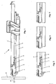
- a drawer slide 1 touch-latch system with integrated touch-latch fitting 5 is shown.
- the housing 6 of the touch-latch fitting 5 is connected to the drawer rail 2 and is temporarily in contact with the carcass rail 4 via the stop 9.
- the connection between the housing 6 of the touch-latch fitting 5 and the drawer rail 2 can through Known methods are: snap connection, rotary connection, insertion technique, screw connection, bayonet connection, Renktagen, etc ....
- Figs. 1 and 2 the drawer slide 1 is closed or has just been opened.
- the touch latch fitting 5 is still (or ready) in the open state.
- the sliding part 7 of the touch-latch fitting 5 is pulled out and not in contact with the stop 9 of the carcass rail 4th
- Fig. 3 the drawer slide 1 is in the closed state, as well as the touch-latch fitting 5.
- the sliding part 7 is in contact with the stopper 9.
- the distance between the housing 6 of the touch-latch fitting 5 and the stopper 9 is comparable to the front gap 24 in FIG. 11.
- the depressed position of the touch-latch fitting 5 can be seen. Among other things, it corresponds to the process of opening the drawer when the front panel of the drawer is pressed.
- the distance between the housing 6 of the touch-latch fitting 5 and the stop 9 is equal to zero (the sliding part 7 of the touch-latch fitting 5 is retracted), so that the unlocking of the system can take place.
- FIG. 5 shows a first principle of a touch-latch system.
- the housing 6 has on its inside eight longitudinally extending grooves 10, which are arranged at a distance of approximately 45 ° around, and wherein each second groove 10 is formed deeper.
- the grooves 10 do not extend over the entire length of the housing. 6
- the rotary member 8 has four projections 13 offset by 90 °, each having an oblique edge 14 at its end.
- the inclination of these edges 14 corresponds to the inclination of the edges 12.
- the projections 13 can be guided displaceably only in the deep grooves 10 of the housing 6.
- the rotary member 8 is located in the housing 6 between the lid 17 and the grooves 10th
- the sliding part 7 has eight projections 11 which engage in all the grooves 10 of the housing 6, since these projections 11 are only as high as the four grooves 10, which are not very deep.
- the sliding part 7 is guided displaceably in the housing 6.
- eight edges 12 are provided at the end of the disk part 7.
- the other end of the disk part 7 forms the stop, which comes temporarily in contact with the stopper 9.
- the spring 15 is preferably in the rotary part. 8
- the number of grooves, edges, and protrusions (45 ° / 90 °) is not the only possibility, there may be other divisions (e.g., 30 ° / 60 °).
- the mounting device 16 on the housing 6 of the touch-latch fitting 5 is used for mounting on the drawer rail second
- a second principle of a touch-latch system is shown. It is a backdrop principle with a heart curve.
- the link pawl 20 is rotatably mounted in the housing 6 and runs in the gate 18.
- the Verrieglungsmechanismus is given by the shape of the heart curve of the gate 18.
- the link pawl 20 runs on one side of the curve of the link 18 when the user presses the touch-latch system or the front panel or when the drawer is closed.
- the link pawl 20 is locked by the force of the spring 15 in the locking position 19 of the link 18. After unlocking, the link pawl 20 continues in the curve until it reaches the straight part of the gate 18 again.
- the mounting device 16 on the housing 6 of the touch-latch fitting 5 is not shown.
- the end of the sliding sleeve 7 can strike the stop 9.
- FIGS. 8 to 10 show a third principle of a touch-latch system. It is a backdrop principle with a 3D curve.
- the link pawl 20 is mounted on the housing 6 via a first arm and its other arm runs in the gate 18.
- the Verrieglungsmechanismus is given by the shape of the 3D curve of the gate 18.
- the mounting device 16 on the housing 6 of the touch-latch fitting 5 is not shown.
- the end of the sliding sleeve 7 can strike the stop 9.
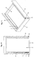
- FIG. 11 there is shown a drawer 21 having a "complete" built-in touch-latch system.
- the drawer 21 is located in the body 22nd
- a touch-latch fitting 5 and a stop 9 in the drawer slide 1 (not shown here) integrated.
- the installation of a touch-latch system requires a larger front gap 24 between the front panel 23 and the body 22, as with conventional drawers with handle, so that the front panel can be pressed for the opening process.
- the front gap 24 may be about 1.5 to 6 mm, preferably 5 mm.
- a buffer 25 is installed between the front panel 23 and the body 22 (either on the front panel 23 or on the body 22).
- the size of the buffer 25 corresponds to the size of the front gap 24.
- a resilient pressure piece on the opposite side of the touch-latch system (at the same position).
- a cylinder is integrated into the guide only with spring and sliding sleeve.
- Another possibility would be the installation of a resilient pressure piece in the automatic retraction so that it is not completely retracted or the displacement of the bolt, which engages in the driver of the automatic retraction.
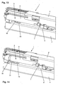
- Figs. 13 and 14 show a locking mechanism with a clip system.
- a resilient hook 30 is attached to the housing 6 of the touch-latch fitting 5, which locks when retracting the drawer in the recess 29 of the carcass rail 4. Now, when the drawer is pulled in to trigger the touch-latch system, the spring force of the touch-latch system is sufficient to push the resilient hook 30 from its lock.
- the length of the recess 29 corresponds approximately to the length of the front gap (path that you can press).
- Fig. 14 the reverse solution of Fig. 13 is shown.
- the resilient hook 31 is mounted on the carcass rail 4 and may e.g. are mounted in the recess 29 and locked in the recess 32 of the housing 6 of the touch-latch fitting 5 when retracting the drawer. Now, when the drawer is pulled in to trigger the touch-latch system, the spring force of the touch-latch system is sufficient to push the resilient hook 31 from its lock.
- a coupling device 33 At the end of the sliding part 7 is a coupling device 33, preferably a hook, and preferably a pad 34 is provided, which is not absolutely necessary if the sliding part 7 has a different geometry.
- the block 34 acts as a stop for the sliding part 7 against the stop 9 and the hooks of the coupling device 33 engage behind the stop 9, as with the damper DE-10256133).
- the rails Drawer rail 2 and cabinet rail 4
- Fig. 16 When retracting the touch-latch fitting 5 and the sliding part 7 with the knob 35 in the recess 36 of the housing 6 is additionally locked (push-pull and release are otherwise always locked). When the touch-latch system is triggered, the spring force of the touch-latch fitting 5 is sufficient to press the knob 35 out of the recess 36.
- Fig. 17 shows a variant for the additional lock.
- the sliding part 7 is always connected to the rotary part 8 via a plug connection (locking pin 37).
- the triggering works as in FIG. 16.
- FIG. 18 shows another variant of the integrated touch-latch system.
- the touch-latch system is integrated or mounted in the drawer frame 26 and abuts the stopper 27 on the body 22.
- One way is that there is only one touch-latch system on one side of the drawer 21, and preferably on the other side a buffer 25 between the body 22 and front panel 23 or a resilient pressure piece in the shop side without touch-latch system.
- FIG. 18 Another possibility according to FIG. 18 is that two touch-latch systems are present in the drawer, one per drawer frame 26, which are both interconnected with transmission means 28, so that there is synchronization and no false triggering. In Fig. 18, only a part of the drawer is shown with this variant.
- Figures 19 and 20 show another embodiment of the present invention with a touch-latch fitting 5, which is integrated in the body side wall 22 and rests with its front free end on the inside of the front panel 23, while the drawer 21 is closed.
- a separate stop 9 or 27 as in the previous embodiments can therefore be omitted.
- one touch latch fitting 5 may be present on one side of the drawer 21, or two, one in the left and one in the right side wall 22 of the body, which in turn may be mechanically coupled to each other via transmission means for synchronization purposes but can work independently.
- a lock on this touch-latch fitting 5 may be provided so that a automatic feed can then be omitted.
- FIG. 21 shows a length adjustability of the touch-latch fitting 5.
- the length adjustment is necessary in order to adjust the front position so that all fronts in the body 22 are in the same plane when the drawers 21 are closed.
- an adjustable stop 38 is mounted at the front free end of the sliding part 7, which is adjustable via an eccentric 39, for example in the form of a slotted screw in the length 40 in the longitudinal extension of the touch-latch fitting 5.
- an eccentric 39 for example in the form of a slotted screw in the length 40 in the longitudinal extension of the touch-latch fitting 5.
- the typical adjustment 40 is about ⁇ 2 mm.
- FIGS. 22-25 show a touch-latch fitting 41 according to a second embodiment, which in turn includes the housing 6, in which the sliding part 7 is received in a longitudinally displaceable manner, at the front free end of which there is a stop 42.
- a worm screw 43 within the stop 42, this is moved relative to the sliding part 7 in the longitudinal adjustment directions 40.
- the sliding part 7 engages longitudinally displaceable in the U-shaped profiled stop 42, which has at the free ends of the U-legs inwardly directed hook-shaped projections 44, so that the sliding part 7 to the stop 42 is exclusively axially displaceable, but not transversely or in other directions.
- a further recess 45 is introduced, for receiving the worm screw 43, the tool lug 46 is freely rotatably mounted in a bore 47 approximately centrally in the recess 45 of the stopper 42.
- knobs 48 are arranged axially one behind the other, in the interstices 49, the spiral screw winding 50 of the worm screw 43 engages.
- FIG. 26 shows an exploded view of a third embodiment of a touch-latch fitting 51 that is almost identical to the embodiment of the touch-latch fitting 5 according to FIG. 5, so that all the reference signs listed there also designate the same components in FIG.
- a sleeve 52 is provided, which contains the touch-latch contour (2D / 3D Koulisse), and which in the housing 6 via a thread (for example, fine thread). is screwed in.
- a thread for example, fine thread
- a fourth embodiment of a touch-latch fitting 53 is shown, wherein the stopper 54 is formed in two parts and includes a threaded spindle 56 and a Abdschreiber 55.
- the threaded spindle 56 can be screwed into the Abdschreiber 55, so that depending on the depth of engagement different front gaps between the front panel 23 and front of the body 22 result.
Abstract
Description
Die Erfindung betrifft ein Touch-Latch System für Möbel mit zueinander relativ bewegbaren Möbelteilen, insbesondere Möbelschublade, Möbeltüre, oder Möbelklappe, nach dem Oberbegriff des Patentanspruches 1.The invention relates to a touch-latch system for furniture with mutually relatively movable furniture parts, in particular furniture drawer, furniture door, or furniture flap, according to the preamble of
Derartige Touch-Latch Systeme werden u.a. bei Schubladen oder Türen ohne Griff auf der Frontblende eingesetzt. Derartige Touch-Latch-Systeme sind aus dem Stand der Technik an sich bekannt , so z.B. ein Touch-Latch-System mit dem Kuli-Prinzip (Drehbewegung), oder ein Touch-Latch-System mit Kulisse (2D-Herzkurve, 3D-Kurve).Such touch-latch systems are u.a. used on drawers or doors without handle on the front panel. Such touch-latch systems are known per se from the prior art, e.g. a Touch-Latch-System with the Kuli-Principle (rotary motion), or a Touch-Latch-System with a backdrop (2D-Herzkurve, 3D-Kurve).
Derartige Vorrichtungen dienen dazu, das Öffnen und Schließen von Schubladen, Türen, Klappen und beliebigen anderen beweglichen Möbelteilen zu ermöglichen, die beispielweise aus ästhetischen Gründen keinen Griff aufweisen. Ein Öffnen und Schließen derartiger beweglicher Möbelteile, beispielweise durch seitliche Betätigung der Frontplatte oder eines anderen zugänglichen Teils, ist unpraktisch bzw. nicht möglich, da nicht bedienbar und lässt keine sichere Bedienung zu.Such devices are used to allow the opening and closing of drawers, doors, flaps and any other movable furniture parts that, for example, have no handle for aesthetic reasons. Opening and closing such movable furniture parts, for example, by lateral actuation of the front panel or other accessible part, is impractical or not possible, since it can not be operated and does not allow safe operation.
Es sind Beschläge zum Öffnen von Schubladen bekannt, die dadurch betätigt werden, dass die Schublade um eine vorgegebene Wegstrecke eingedrückt wird und anschließend durch einen Federmechanismus ausgefahren wird. Diese Funktion wird in bekannter Weise über sogenannte Touch-Latch-Beschläge erreicht.There are fittings for opening drawers are known, which are actuated by the drawer is pressed by a predetermined distance and then extended by a spring mechanism. This function is achieved in a known manner via so-called touch-latch fittings.
Die DE 198 21014 A1 offenbart eine Vorrichtung zum Öffnen eines Verschlusselementes, insbesondere einer Schublade, Tür, oder Klappe eines Möbelstückes, wobei eine Antriebseinheit zum Öffnen der Schublade, Tür, oder Klappe vorgesehen ist und ein Auslöseelement mit insbesondere einem el. Kondensator insbesondere in der Frontblende der Schublade, Tür, oder Klappe vorgesehen ist, zum Betätigen der Antriebseinheit.DE 198 21014 A1 discloses a device for opening a closure element, in particular a drawer, door, or flap of a piece of furniture, wherein a drive unit for opening the drawer, door, or flap is provided and a triggering element with in particular an el Front panel of the drawer, door, or flap is provided for operating the drive unit.
Die DE 100 08 350 A1 offenbart eine Vorrichtung zum Öffnen einer Möbelabdeckung, insbesondere einer Schublade, Tür, oder Klappe eines Möbelstückes, wobei eine Kombination eines Touch-Latch-Beschlages mit einem Dämpfer vorgesehen ist und der Touch-Latch-Beschlag an einer separaten Unterschale der Möbelabdeckung befestigt ist.DE 100 08 350 A1 discloses a device for opening a furniture cover, in particular a drawer, door, or flap of a Piece of furniture, wherein a combination of a touch-latch fitting is provided with a damper and the touch-latch fitting is attached to a separate lower shell of the furniture cover.
Die EP 1 183 963 A1 offenbart einen Adapter und eine Schublade mit diesem Adapter, der wenigstens zwei Funktionselemente aufweist, durch die der öffnungs-und/oder Schließvorgang der Schublade beeinflussbar ist. Als Funktionselemente sind Dämpfungen, Ver- und Entriegelungen, Motoren und Federn zum Öffnen und Schließen der Schublade und auch Touch-Latch-Beschläge mit Labyrinth und Antriebsfeder offenbart. Die Touch-Latch-Beschläge sind im hinteren Bereich der Schublade unterhalb des Schubladenbodens mit der Schubladenzarge verbunden, wodurch Stauraum in der Schublade verloren geht.
Die DE 295 07 917 U1 und EP-743032 B1 offenbaren ein Unterflur-Schienensystem für Schubkästen mit einem Touch-Latch-System mit einem den Schubkasten in Schließstellung sichernden federbelasteten Zuhalteelement, welches unterhalb des Führungsschienensystems an der Unterseite der feststehenden Korpusschiene angeordnet ist. Das federbelastete Zuhalteelement ist eine Rastklinke, die mittels eines an der ausfahrbaren Auszugsschiene angeordneten Mitnehmers verfahrbar ist. Die Rastklinke ist in einem flachen Führungskörper mit einer Führungsbahn mit Wendeschleife in Auszugsrichtung des Schubkastens verschiebbar. Nachteil ist, dass durch die Anordnung des Touch-Latch-System unterhalb des Führungsschienensystems an der Unterseite der feststehenden Korpusschiene Stauraum für die darunter liegende Schublade verloren geht.DE 295 07 917 U1 and EP-743032 B1 disclose an underfloor rail system for drawers with a touch-latch system with a drawer in the closed position locking spring-loaded locking element, which is arranged below the guide rail system on the underside of the fixed carcass rail. The spring-loaded locking element is a latch which can be moved by means of a arranged on the extendable drawer rail driver. The latch is slidable in a flat guide body with a guideway with turning loop in the extension direction of the drawer. Disadvantage is that the arrangement of the touch-latch system below the guide rail system at the bottom of the fixed cabinet rail storage space is lost for the underlying drawer.
Die EP 1 314 842 A1 offenbart eine Vorrichtung zum Öffnen und Schließen eines beweglichen Möbelteils, insbesondere einer Schublade, Tür oder Klappe, die einem Touch-Latch-System entspricht. Die Vorrichtung umfasst zwei Auslöse-und Antriebseinheiten, die jeweils ein durch äußere Krafteinwirkung beeinflussbares Auslöseelement und ein mit dem Auslöselement gekoppeltes Antriebselement zum Bewegen des Möbelteils aufweisen, und mindestens ein Verriegelungselement zur Verriegelung des Möbelteils in der geschlossenen Stellung und Freigabe des Möbelteils in Abhängigkeit einer äußeren Krafteinwirkung auf mindestens ein Auslöselement, wobei die beiden Auslöse-/Antriebseinheiten synchron und im wesentlichen spielfrei durch weg- und kraftübertragende Mittel miteinander gekoppelt sind. Die gesamte Vorrichtung ist im vorderen Bereich der Schublade angeordnet und ist bis auf korpusfeste Anschläge auf dem Schubladenboden montiert. Vorteil ist, dass man überall auf die Frontblende drücken kann, um die Schublade zu öffnen, da ein großer Auslösebereich vorhanden ist. Nachteil ist die aufwendige und kostenintensive Konstruktion, und auch der große Auslösebereich wegen einem unbeabsichtigten Auslösen. Wenn zwei unabhängige an sich bekannte Touch-Latch-Beschläge vorgesehen sind, wird manchmal nur ein Beschlag ausgelöst, der andere nicht. Weiterer Nachteil ist, dass die Vorrichtung relativ viel Bauraum unterhalb und neben der Schublade in Anspruch nimmt und daher Stauraum für die Schublade an sich verloren geht.
Die DE 101 18 394 A1 offenbart ein Touch-Latch-System mit Drehbewegung und Verrieglungsstift für Türen, Klappen und Auszüge von Möbeln. Die genaue Anordnung des Touch-Latch-Systems an den Möbeln ist nicht offenbart.DE 101 18 394 A1 discloses a touch-latch system with rotary movement and locking pin for doors, flaps and extracts of furniture. The exact arrangement of the touch-latch system on the furniture is not disclosed.
Die DE 100 60 655 A1 offenbart ein Touch-Latch-System mit Drehbewegung für Türen, Klappen und Auszüge von Möbeln. Die genaue Anordnung des Touch-Latch-Systems an den Möbeln ist nicht offenbart.DE 100 60 655 A1 discloses a touch-latch system with rotary motion for doors, flaps and pull-outs of furniture. The exact arrangement of the touch-latch system on the furniture is not disclosed.
Die EP 0 131 909 A2 offenbart ein Touch-Latch-System für Aschenbecher im Auto mit dem Kuli-Prinzip (Drehbewegung und 8-Nuten System). Das Touch-Latch-System ist im hinteren Bereich des Auto-Aschenbechers zwischen der Rückwand des Klappteils und der Unterseite der Niesche für den Aschenbecher angeordnet.EP 0 131 909 A2 discloses a touch-latch system for ashtrays in the car with the coolie principle (rotary motion and 8-slot system). The touch-latch system is located in the rear of the car ashtray between the rear wall of the hinged part and the underside of the ashes for the ashtray.
Die GB 2 117 472 A offenbart ein zylinderförmiges Touch-Latch-System mit 3D-Kurve als Türknauf für eine Gebäudetüre, nicht aber für ein Möbelstück.
Aufgabe der vorliegenden Erfindung ist es, ein eingangs geschildertes gattungsgemäßes Touch-Latch-System bereit zu stellen, welches eine einfache und kostengünstige Verstellung der Frontblende ermöglicht.Object of the present invention is to provide an initially described generic touch-latch system, which allows a simple and inexpensive adjustment of the front panel.
Zur Lösung der gestellten Aufgaben ist die vorliegende Erfindung durch die Merkmale des Patentanspruches 1 gekennzeichnet.To achieve the objects, the present invention is characterized by the features of
Wesentlich dabei ist, dass der Touch-Latch-Beschlag längenverstellbar ausgebildet ist.It is essential that the touch-latch fitting is designed to be adjustable in length.
Vorteil ist, dass durch die Längenverstellbarkeit des Touch-Latch-Beschlags eine einfache und kostengünstige Verstellung der Frontblende ermöglicht wird.The advantage is that a simple and cost-effective adjustment of the front panel is made possible by the length adjustability of the touch-latch fitting.
Bevorzugt wird, wenn das gesamte Touch-Latch-System oder zumindest der Touch-Latch-Beschlag des Touch-Latch-Systems vollständig oder nahezu vollständig in bereits vorhandene Bauteile des Möbels integriert ist, nämlich innerhalb des Schienensystems (insbesondere in der Schubladenschiene insbesondere an deren einen freien Ende im Frontbereich), oder innerhalb der Schubladenzarge (Dekor) insbesondere über dem Schienensystem insbesondere im Rückwandbereich, oder aber innerhalb einer eigens dafür geschaffenen Ausnehmung im Material des Möbelkorpus insbesondere im Rückwandbereich. Es kann auch vorgesehen sein, dass der Touch-Latch-Beschlag in der Tür integriert wird.Preferably, when the entire touch-latch system or at least the touch-latch fitting of the touch-latch system is fully or almost completely integrated into existing components of the furniture, namely within the rail system (especially in the drawer rail, in particular at their a free end in the front area), or within the drawer (decor) in particular over the rail system, in particular in the rear wall area, or within a specially created recess in the material of the furniture body in particular in the rear wall area. It can also be provided that the touch-latch fitting is integrated in the door.
Vorteil ist, dass durch das Integrieren des Touch-Latch-Beschlags in bereits vorhandene Bauteile des Möbels kein zusätzlicher Bauraum für den Touch-Latch-Beschlag benötigt wird, so dass der Stauraum für zu lagernde Gegenstände im Möbelkorpus, insbesondere der Schublade, in erwünschter Weise beibehalten bleiben kann, bzw. gegenüber Möbeln mit Touch-Latch-Systemen aus dem Stand der Technik erheblich vergrößert ist.The advantage is that no additional space for the touch-latch fitting is required by integrating the touch-latch fitting into existing components of the furniture, so that the storage space for items to be stored in the furniture body, especially the drawer, in the desired manner can be maintained, or compared to furniture with touch-latch systems of the prior art is considerably increased.
Die erfindungsgemäße Möbelschublade beinhaltet mindestens ein Touch-Latch-System mit mindestens einem Touch-Latch-Beschlag, wobei bevorzugt mindestens eine Ausziehführung in der Möbelschublade vorgesehen ist, die mindestens eine Korpusschiene und eine Schubladenschiene und gegebenenfalls eine Mittelschiene beinhaltet.The furniture drawer according to the invention comprises at least one touch-latch system with at least one touch-latch fitting, wherein preferably at least one pull-out in the furniture drawer is provided which includes at least one cabinet rail and a drawer rail and possibly a center rail.
In einer ersten Ausführungsform der Erfindung beinhaltet der Touch-Latch-Beschlag mindestens ein vorzugsweise zylindrisches Gehäuse und einen Schiebe- und/oder Drehteil, wobei der Touch-Latch-Beschlag über ein erstes Teil (Gehäuse oder Schiebe- und/oder Drehteil) mittelbar oder unmittelbar mit einer der Schienen (Korpusschiene, Mittelschiene, Schubladenschiene) verbunden ist und über ihr jeweils anderes Teil (Schiebe- bzw. Drehteil oder Gehäuse) zeitweilig während des Öffnens und Schließens mittelbar oder unmittelbar mit einer anderen Schiene (Korpusschiene, Mittelschiene, Schubladenschiene) in Kontakt liegt bzw. koppelbar ist.In a first embodiment of the invention, the touch-latch fitting includes at least one preferably cylindrical housing and a sliding and / or rotating part, wherein the touch-latch fitting via a first part (housing or sliding and / or rotating part) directly or indirectly with one of the rails (cabinet rail, middle rail, drawer rail) is connected and on her other Part (sliding or rotating part or housing) temporarily during the opening and closing directly or indirectly with another rail (carcass rail, center rail, drawer rail) is in contact or can be coupled.
Der Touch-Latch-Beschlag ist integriert in den bereits vorhandenen Bauteilen der Schublade und ist daher im eingefahrenen und/oder ausgefahrenen Zustand der Schublade/Türe/Klappe unsichtbar oder nahezu unsichtbar in dem Möbel angeordnet. Kein Teil des Touch-Latch-Systems kommt während der Bewegung der Schublade aus dem Korpus heraus oder steht während der eingezogenen oder ausgefahrenen Schublade/Türe/Klappe ab, so dass keine Verletzungsgefahr für den Nutzer und auch keine optische Störung vorliegt, sondern ein harmonisches Design.The touch-latch fitting is integrated in the existing components of the drawer and is therefore invisible or almost invisible in the retracted and / or extended state of the drawer / door / flap arranged in the furniture. No part of the touch-latch system comes out of the body during the movement of the drawer or stands out during the retracted or extended drawer / door / flap, so that there is no risk of injury to the user and no optical interference, but a harmonious design ,
Es sind auch keine aufwändigen Anbauteile für das erfindungsgemäße Touch-Latch-System notwendig, wie ein Adapter, eine Zusatzleiste oder einen Anschlag, nach dem Stand der Technik, die genau positioniert werden müssten.There are also no complex attachments for the touch-latch system according to the invention necessary, such as an adapter, an additional strip or a stop, according to the prior art, which would have to be positioned accurately.
Auch sind keine Bohrungen notwendig, um das Touch-Latch-System in der Schublade einzustecken.Also, no holes are necessary to plug the touch-latch system into the drawer.
Die Erfindung ist ausdrücklich nicht auf eine Schublade begrenzt, sondern der Aufsatz auf der Führung kann beliebig sein, so z.B. eine Schublade, ein Drahtkorb, eine Platte, etc.. Auch ist das erfindungsgemäße Touch-Latch-System natürlich in Zusammenhang mit Möbeltüren und Möbelklappen verwendbar, so dass keine Einschränkung auf Schienensysteme erfolgen soll.The invention is expressly not limited to a drawer, but the attachment on the guide may be arbitrary, such. a drawer, a wire basket, a plate, etc. Also, the touch-latch system according to the invention, of course, in connection with furniture doors and furniture flaps used, so that no restriction on rail systems should be made.
Insbesondere ist vorgesehen, dass das Gehäuse des Touch-Latch-Beschlags mittelbar oder unmittelbar mit der Schubladenschiene, vorzugsweise im vorderen Bereich der Schubladenschiene verbunden ist, und der Schiebe- und/oder Drehteil mittelbar oder unmittelbar an der Korpusschiene, vorzugsweise auf einem auf der Korpusschiene angebrachten Anschlag anschlägt.In particular, it is provided that the housing of the touch-latch fitting is indirectly or directly connected to the drawer rail, preferably in the front region of the drawer rail, and the sliding and / or rotary member directly or indirectly on the cabinet rail, preferably on a on the cabinet rail attached stop strikes.
Eine alternative Ausführung der Erfindung sieht vor, dass das Gehäuse des Touch-Latch-Beschlags mittelbar oder unmittelbar mit der Korpusschiene, verbunden ist, und der Schiebe- und/oder Drehteil des Touch-Latch-Beschlags mittelbar oder unmittelbar an der Schubladenschiene, vorzugsweise auf einem auf der Schubladenschiene angebrachten Anschlag anschlägt.An alternative embodiment of the invention provides that the housing of the touch-latch fitting is indirectly or directly connected to the carcass rail, and the sliding and / or rotating part of the touch-latch fitting directly or indirectly on the drawer rail, preferably strikes a mounted on the drawer rail stop.
Das Touch-Latch-System ist mit einem in der Führung integrierten Dämpfer (z.B. Dämpfer wie in der DE-10256133 oder EP-03012770.8) austauschbar. Dies gilt insbesondere für die Anordnung des Touch-Latch-Systems am freien Ende einer Schiene, z.B. der Schubladenschiene. Vorteil ist, dass der Kunde bzw. der Monteur "in der letzten Minute" entscheiden kann, ob er den Dämpfer oder das Touch-Latch-System einsetzen möchte. Es kann vorgesehen sein, dass ein Touch-Latch-System auf einer Seite und ein Dämpfer auf der anderen Seite montiert werden.The touch-latch system is interchangeable with a damper integrated in the guide (e.g., damper as in DE-10256133 or EP-03012770.8). This applies in particular to the arrangement of the touch-latch system at the free end of a rail, e.g. the drawer rail. The advantage is that the customer or the fitter can decide "at the last minute" whether he wants to use the damper or the touch-latch system. It may be provided that a touch-latch system be mounted on one side and a damper on the other side.
Vorzugsweise ist ein einziges Touch-Latch-System pro Schublade vorhanden, es kann aber in anderen Ausführungen auf jeder Seite der Schublade ein insbesondere identisches Touch-Latch-System angeordnet sein oder auch mehrere unterschiedliche Touch-Latch-Systeme an unterschiedlichen Positionen in der Schublade bzw. dem Möbelkorpus vorhanden sein. Bevorzugt wird aber ein einziges Touch-Latch-System pro Schublade und es wird ein Zusatzelement als gefederter Frontspalt-Anschlag auf der gegenüberliegenden Seite des Touch-Latch-Systems montiert.Preferably, a single touch-latch system per drawer is present, but it can be arranged in different versions on each side of the drawer a particular identical touch-latch system or even several different touch-latch systems at different positions in the drawer or be present to the furniture body. However, preference is given to a single touch-latch system per drawer and an additional element is mounted as a sprung front-gap stop on the opposite side of the touch-latch system.
Um aber Fehlfunktionen zu vermeiden, ist ein Touch-Latch-System nur in einer einzigen Führung montiert. Mit zwei ungekoppelten Touch-Latch-Systemen, kommt es zu Fehlfunktionen, wenn man außerhalb des Auslösebereiches zum Öffnen drückt.But to avoid malfunctions, a touch-latch system is mounted in a single guide. With two uncoupled touch-latch systems, it malfunctions when opening outside the trip range.
Der Auslösebereich ist mit der Position des Touch-Latch-Systemes vordefiniert und entspricht nicht unbedingt der ganzen Frontblendenfläche (je nach Frontblendenbreite). Für schmale Schubladen ist es die ganze Frontblendenfläche, für breite Schubladen ist die Auslösung auf der Seite mit Touch-Latch leicht zu erzielen, je weiter vom Touch-Latch-System gedrückt wird, desto schwieriger bis unmöglich wird eine Auslösung (z.B. bei 1200cm breiten Schubladen).The trip range is predefined with the position of the touch-latch system and does not necessarily correspond to the entire front panel (depending on the front panel width). For narrow drawers it is the whole front panel, for wide drawers the release on the side with touch-latch is easy too the further you press the touch-latch system, the harder it becomes impossible to trigger (eg with 1200cm wide drawers).
Durch das vorzugsweise einseitig bestückte Touch-Latch-System muss auf der gegenüberliegenden Seite ein Zusatzelement als gefederter Frontspalt-Anschlag angebracht werden. Somit ist ein gleichmäßiger Spalt zwischen Front und Korpus über die gesamte Frontbreite gewährleistet (wichtig im geschlossenen Zustand, da das Touch-Latch-System einen größeren Frontspalt fordert: ca. 5 mm statt nur ca. 2 mm, um die Front zum Öffnen drücken zu können). Dazu würde eine eventuell vorhandene Standard-Einzugsautomatik die gegenüberliegende Seite der Front zu weit zuziehen.By preferably one-sided equipped touch-latch system must be mounted on the opposite side of an additional element as a sprung front gap stop. Thus, a uniform gap between the front and body over the entire front width guaranteed (important in the closed state, since the touch-latch system requires a larger front gap: about 5 mm instead of only about 2 mm, to push the front to open can). This would be a possibly existing standard automatic retraction pull the opposite side of the front too far.
Dies ist nicht notwendig, wenn es nur eine Ausziehführung pro Schublade gibt, die dann unten und mittig an der Schublade angeordnet ist.This is not necessary if there is only one pull-out guide per drawer, which is then arranged at the bottom and in the middle of the drawer.
Das Zusatzelement zu einem einzigen Touch-Latch-System ist bevorzugt ein Puffer, der z.B. auf der Innenseite der Frontblende oder allgemein am Korpus angeordnet ist.The attachment to a single touch-latch system is preferably a buffer, e.g. is arranged on the inside of the front panel or generally on the body.
Auch kann das Zusatzelement ein federndes Druckstück sein, das in der gegenüberliegenden Position des Touch-Latch-Systems montiert ist.Also, the additional element may be a resilient pressure piece which is mounted in the opposite position of the touch-latch system.
Es kann vorgesehen sein, dass zwei Touch-Latch-Systeme pro Schublade (ein pro Ausziehführung) vorhanden sind.It can be provided that there are two touch-latch systems per drawer (one per pull-out guide).
In einer Ausführungsform der vorliegenden Erfindung sind die zwei Schiebeteile und/oder Drehteile der Touch-Latch-Beschläge über Übertragungsmittel (z.B. Seile, Umlenkrollen, Verbindungsstangen), vorzugsweise unter dem Schubladenboden oder hinter der Schubladenrückwand, verbunden bzw. gekoppelt.In one embodiment of the present invention, the two sliding parts and / or rotating parts of the touch-latch hardware are coupled via transmission means (e.g., cables, pulleys, tie bars), preferably under the drawer bottom or behind the drawer back panel.
In einer anderen Ausführungsform der vorliegenden Erfindung sind die zwei Touch-Latch-Systeme unabhängig voneinander in der Führung angebracht.In another embodiment of the present invention, the two touch-latch systems are independently mounted in the guide.
Unabhängige Touch-Latch-Systeme mit Verriegelung funktionieren gut bei schmalen Schubladen, da der Auslösebereich eigentlich der ganzen Frontblendenfläche entspricht.Independent touch-latch systems with locking work well with narrow ones Drawers, as the release area actually corresponds to the entire front panel.
Insbesondere werden die zwei Touch-Latch-Systeme im geschlossenen Zustand verriegelt, womit ein gleichmäßiger Frontspalt gewährleistet ist und die Einzugsautomatik entfällt. Die Schublade kann sich nicht unbeabsichtigt öffnen, da sie verriegelt ist. Im Normalfall ist sie durch die Einzugsautomatik verriegelt.
Für breite Schubladen mit 2 Touch-Latch-Systeme mit Verriegelung kann es passieren, dass beim Drücken (= beim Öffnen) ein Touch-Latch-System entriegelt wird und das andere nicht weil man außerhalb des Auslösebereiches gedrückt hat. Wenn dies der Fall ist, muss man auf der Seite des noch verriegelten Touch-Latch-Systems drücken und es entriegelt sich. Dieser "Fangmechanismus" toleriert die Fehlauslösungen.In particular, the two touch-latch systems are locked in the closed state, which ensures a uniform front gap and eliminates the automatic catch. The drawer can not open unintentionally because it is locked. Normally, it is locked by the automatic retraction.
For wide drawers with 2 touch-latch systems with interlocking it can happen that when pressing (= when opening) one touch-latch system is unlocked and the other one is not pressed because one has pressed outside of the tripping area. If this is the case, you have to press on the side of the still locked touch-latch system and it unlocks. This "catch mechanism" tolerates the false alarms.
Die Verriegelung des Touch-Latch-Systems erfolgt in einer bevorzugten Ausführung der Erfindung über einen federnden Haken zwischen dem Gehäuse des Touch-Latch-Beschlags, und der gegenüberliegenden Schiene.The locking of the touch-latch system is carried out in a preferred embodiment of the invention via a resilient hook between the housing of the touch-latch fitting, and the opposite rail.
In einer alternativen Ausführung erfolgt die Verriegelung des Touch-Latch-Systems über eine Koppelvorrichtung am Ende des Schiebeteiles des Touch-Latch-Beschlags und eine zusätzliche Verriegelung innerhalb des Touch-Latch-Systems.In an alternative embodiment, the locking of the touch-latch system takes place via a coupling device at the end of the sliding part of the touch-latch fitting and an additional locking within the touch-latch system.
Anstatt einer Einzugsautomatik kann ein Touch-Latch-System eingesetzt werden, vorzugsweise an der Korpusschiene. Vorzugsweise hat dieses Touch-Latch-System dieselben Aussenabmessungen wie die Einzugsautomatik. Die Touch-Latch-Funktion wird vorzugsweise über eine Herzkurve realisiert. Die Verriegelung ist dieselbe wie bei der Einzugsautomatik, wo ein Haken gekippt wird und auf einer Kante des Gehäuses der Einzugsautomatik rastet.Instead of a automatic retraction, a touch-latch system can be used, preferably on the cabinet rail. Preferably, this touch-latch system has the same external dimensions as the automatic retraction. The touch-latch function is preferably realized via a heart curve. The lock is the same as the automatic retractor, where a hook is tilted and snaps onto one edge of the auto-retractable housing.
Ist der Auslöseweg des Touch-Latch-Systems kleiner als der Einzugsweg einer optional vorhandenen Einzugsautomatik, dann wird der Öffnungsweg der Schublade begrenzt, unabhängig vom Gewicht der Schublade. Um die Schublade ganz zu öffnen, muss noch einmalgezogen werden. Dies kann als zusätzliches Sicherungsmerkmal erwünscht sein, um ein unbeabsichtigtes zu weites Öffnen der Schublade zu vermeiden.If the triggering distance of the touch-latch system is smaller than the feed path of an optional automatic feed mechanism, then the opening path of the drawer is limited, regardless of the weight of the drawer. To open the drawer completely, you must pull it once more. This can be as additional Security feature may be desirable to prevent unintentional too wide opening of the drawer.
Ist aber der Auslöseweg des Touch-Latch-Systems länger als der Einzugsweg einer optional vorhandenen Einzugsautomatik, dann hält die Einzugsautomatik die Schublade nicht geschlossen, sondern stößt die Lade über den Einzugsautomatik-Weg auf.However, if the triggering path of the touch-latch system is longer than the feed path of an optional automatic feed mechanism, then the automatic feed mechanism does not hold the drawer closed, but pushes the drawer through the automatic retraction path.
Der Touch-Latch-Beschlag des vom Prinzip her bekannten Touch-Latch-Systems kann eine besondere Kurve, z.B. Herzkurve, 3D-Kurve oder ein beliebiges anderes Touch-Latch-Prinzip aufweisen.The touch-latch hardware of the principle known touch-latch system may have a particular curve, e.g. Heart curve, 3D curve or any other touch-latch principle have.
In einer anderen Variante der Erfindung kann das Touch-Latch-System dabei links oder rechts oder mittig von der Schublade montiert sein, z.B. eingebohrt, z.B. im Schubladenboden oder in der Zarge, oder mit Adapter irgendwo geschraubt sein, oder in der Korpusseite eingebohrt. Das zum Touch-Latch-System zugehörige Anschlagteil ist bevorzugt im Korpus montiert.In another variant of the invention, the touch-latch system can be mounted on the left or right or in the middle of the drawer, e.g. drilled, e.g. in the drawer bottom or in the frame, or with adapter screwed somewhere, or drilled in the cabinet side. The associated to the touch-latch system stop member is preferably mounted in the body.
Es können zwei solche Touch-Latch-Systeme in der Schublade vorhanden sein, die über Übertragungsmittel verbunden sind oder aber zwei Touch-Latch-Systeme, die unabhängig voneinander sind.There may be two such touch-latch systems in the drawer connected via transmission means or two touch-latch systems which are independent of each other.
Erfindungsgemäß erfolgt die Längenverstellbarkeit des Touch-Latch-Beschlags durch drei verschiedene Grundvarianten, nämlich eine Verstellung des gesamten Touch-Latch-Beschlags, oder aber nur durch eine Verstellung zwischen definierten Einzelteilen des Touch-Latch-Beschlags, oder aber durch eine Verstellung eines Anschlages, der mit dem Touch-Latch-Beschlag zusammenwirkt. Natürlich könnten diese drei Grundvarianten auch beliebig miteinander kombiniert werden.According to the invention, the length adjustability of the touch-latch fitting is effected by three different basic variants, namely an adjustment of the entire touch-latch fitting, or else only by an adjustment between defined individual parts of the touch-latch fitting, or by an adjustment of a stop, which cooperates with the touch-latch fitting. Of course, these three basic variants could also be arbitrarily combined.
Bevorzugt erfolgt eine einfache und kostengünstige aller zuvor beschriebenen drei Grundvarianten der Längenverstellbarkeit des Touch-Latch-Beschlags des Touch-Latch-Systems entweder über eine Exzenterverstellung, oder aber über eine Schraubverstellung, oder aber über eine Rastpositionenverstellung. Natürlich könnten diese drei Ausführungen der Verstellung ebenfalls beliebig miteinander kombiniert werden. Die Längsverstellung hat den Vorteil, dass die Position der Front der Schublade verstellt werden kann.Preferably, a simple and inexpensive all three previously described variants of the length adjustability of the touch-latch fitting of the touch-latch system is carried out either via an eccentric adjustment, or via a screw adjustment, or via a locking position adjustment. Of course, these three versions of the adjustment could also be arbitrary with each other be combined. The longitudinal adjustment has the advantage that the position of the front of the drawer can be adjusted.
Die Exzenterverstellung des Touch-Latch-Beschlags weist dabei entweder eine Exzenterschraube mit mindestens einer Nocke oder aber eine Schneckenschraube mit spiralförmiger Schneckenwindung auf. Der Verdrehwinkel der Exzenterschraube liegt zwischen 90° und 180°, jedoch bis maximal 360°, der Verdrehwinkel der Schneckenschraube zwischen 360° und 540°, kann aber auch 720° oder mehr betragen, je nach erwünschtem Verstellweg.The eccentric adjustment of the touch-latch fitting has either an eccentric screw with at least one cam or a worm screw with spiral screw winding. The angle of rotation of the eccentric screw is between 90 ° and 180 °, but up to a maximum of 360 °, the angle of rotation of the screw between 360 ° and 540 °, but can also be 720 ° or more, depending on the desired adjustment.
Die Schraubverstellung des Touch-Latch-Beschlags weist eine Schraubhülse auf, die in oder auf das Gehäuse des Touch-Latch-Beschlages geschraubt ist, oder aber weist eine Gewindespindel eines Anschlages auf, die mit einem Schiebeteil und/oder einem Abdrücker des Touch-Latch-Beschlages längenverstellbar mittels Schraubbewegungen verbunden ist.The screw adjustment of the touch-latch fitting has a threaded sleeve, which is screwed into or on the housing of the touch-latch fitting, or has a threaded spindle of a stop which with a sliding part and / or a push-off of the touch-latch -Beschlages length adjustable is connected by screwing movements.
Die Mittel zur Längenverstellbarkeit, insbesondere Exzenterverstellungen des Touch-Latch-Beschlags wirken bevorzugt zwischen dem Schiebeteil des Touch-Latch-Beschlags und einem an dem vorderen freien Ende des Schiebeteils angeordneten Anschlag. Die Mittel zur Längenverstellbarkeit, insbesondere Schraubverstellungen wirken bevorzugt zwischen Gehäuse des Touch-Latch-Beschlags und dessen Schiebeteil, oder aber zwischen zwei Bauteilen des Anschlages am vorderen freien Ende des Touch-Latch-Beschlags.The means for length adjustment, in particular eccentric adjustments of the touch-latch fitting preferably act between the sliding part of the touch-latch fitting and arranged at the front free end of the sliding part stop. The means for length adjustment, in particular screw adjustments preferably act between the housing of the touch-latch fitting and its sliding part, or between two components of the stop at the front free end of the touch-latch fitting.
In einer anderen Variante der Erfindung kann es vorgesehen sein, dass die Federkraft der Feder des Touch-Latch-Beschlags einstellbar ausgebildet ist. Z.B. ist für eine Schwerlastschublade eine Feder mit einer größeren Federkraft von Vorteil, für eine Schublade, die nur geringe Tragfähigkeit aufweisen muss, genügt eine Touch-Latch-Beschlag-Feder mit relativ geringer Federkraft.In another variant of the invention, it may be provided that the spring force of the spring of the touch-latch fitting is designed to be adjustable. For example, For a heavy duty drawer, a spring with a larger spring force is advantageous, for a drawer that has only low capacity, a touch-latch fitting spring with a relatively low spring force is sufficient.
Die Federkraft kann entweder in Stufen eingestellt werden, oder aber stufenlos. Bei einer Einstellbarkeit der Touch-Latch-Beschlag-Feder in vordefinierten Stufen hängt z.B. das Ende der Feder auf verschiedenen Raststufen im Gehäuse des Touch-Latch-Beschlags. Bei einer stufenlosen Einstellbarkeit der Touch-Latch-Beschlag-Feder ist diese z.B. über eine Verstellschraube einstellbar, die am Boden des Gehäuses des Touch-Latch-Beschlags angebracht ist.The spring force can be adjusted either in stages, or stepless. If the touch-latch-fitting spring is adjustable in predefined stages, the end of the spring, for example, hangs at different latching steps in the housing of the touch-latch fitting. With infinitely variable adjustability of the touch-latch fitting spring this is adjustable, for example via an adjusting screw, which is attached to the bottom of the housing of the touch-latch fitting.
Eine Vorbestückung ist auch denkbar, d.h. für eine Schwerlastschublade bzw. Tür wird ein Touch-Latch-Beschlag mit einer Feder mit einer großen Federkraft eingesetzt, und für eine normale oder leichte Schublade bzw. Tür wird ein Touch-Latch-Beschlag mit einer Feder mit einer niedrigeren Federkraft eingesetzt.A Vorbestückung is also conceivable, i. for a heavy duty drawer or door, a touch-latch fitting is used with a spring with a large spring force, and for a normal or light drawer or door, a touch-latch fitting is used with a spring with a lower spring force.
Natürlich kann eine stufenlose sowie stufige Einstellbarkeit der Touch-Latch-Beschlag-Feder innerhalb eines Touch-Latch-Beschlags oder einer Schublade auch kombiniert werden.Of course, a stepless and gradual adjustability of the touch-latch fitting spring within a touch-latch fitting or drawer can also be combined.
- Fig. 1 :Fig. 1:
- isometrische Ansicht einer Ausziehführung mit Touch-Latch-System im offenen Zustand kurz vor dem Schließen bzw. kurz nach dem ÖffnenIsometric view of a pull-out guide with touch-latch system in the open state shortly before closing or shortly after opening
- Fig. 2 :Fig. 2:
- Detailansicht der Fig. 1 (Zoom auf das Touch-Latch-System und Anordnung in den Schienen)Detail view of FIG. 1 (zoom on the touch-latch system and arrangement in the rails)
- Fig. 3 :3:
- Zoom wie in Fig. 2, wobei das Touch-Latch-System sich im geschlossenen Zustand befindet, ohne Wirkung einer Handkraft eines Benutzers für das Öffnen der SchubladeZoom as in Fig. 2, wherein the touch-latch system is in the closed state, without effect of a manual force of a user for the opening of the drawer
- Fig.4 :Fig.4:
- Zoom wie in Fig. 2, wobei das Touch-Latch-System sich in gedrückter Position befindet, mit Wirkung einer Handkraft eines Benutzers für das Öffnen der SchubladeZoom as shown in Fig. 2, wherein the touch-latch system is in the depressed position, with the help of a hand force of a user for the opening of the drawer
- Fig. 5 :Fig. 5:
- Explosionsansicht des Touch-Latch-Beschlags (mit Kuli-Prinzip)Exploded view of the Touch-Latch fitting (with Kuli principle)
- Fig. 6 :Fig. 6:
- Explosionsansicht des Touch-Latch-Beschlags (mit Herz-Kurve)Exploded view of the touch latch fitting (with heart curve)
- Fig. 7 :Fig. 7:
- Detailansicht von oben der Herz-KurveDetail view from above of the heart curve
- Fig. 8 :Fig. 8:
- Explosionsansicht des Touch-Latch-Beschlags (mit 3D-Kurve)Exploded view of the touch-latch fitting (with 3D curve)
- Fig. 9 :Fig. 9:
- Detailansicht von der Seite der 3D-KurveDetail view from the side of the 3D curve
- Fig. 10 :Fig. 10:
- Detailansicht von oben der 3D-KurveDetail view from above of the 3D curve
- Fig. 11 :Fig. 11:
- Isometrische Ansicht einer Schublade mit einseitigem Touch-Latch-System ohne Verriegelung und Puffer auf der anderen Seite, jedoch mit beidseitiger EinzugsautomatikIsometric view of a drawer with one-sided touch-latch system without locking and buffer on the other side, but with double-sided automatic retraction
- Fig. 12 :Fig. 12:
- Ansicht von oben der Fig. 11Top view of FIG. 11
- Fig. 13 :Fig. 13:
- Detailansicht einer Schubladenführung mit Touch-Latch-System mit einem ersten VerriegelungssystemDetail view of a drawer slide with touch-latch system with a first locking system
- Fig. 14 :Fig. 14:
- Detailansicht einer Schubladenführung mit Touch-Latch-System mit einem zweiten VerriegelungssystemDetail view of a drawer slide with touch-latch system with a second locking system
- Fig. 15 :Fig. 15:
- Detailansicht einer Schubladenführung mit Touch-Latch-System mit einem dritten VerriegelungssystemDetail view of a drawer slide with touch-latch system with a third locking system
- Fig.16:Figure 16:
- Schnittansicht des Touch-Latch-Systemes mit dem dritten Verriegelungssystem nach Figur 15, im verriegelten ZustandSectional view of the touch-latch system with the third locking system of Figure 15, in the locked state
- Fig.17:Figure 17:
- Schnittansicht eines Touch-Latch-Systemes mit einem vierten Verriegelungssystem, im verriegelten ZustandSectional view of a touch-latch system with a fourth locking system, in the locked state
- Fig. 18:Fig. 18:
- Schublade mit 2 gekoppelten Touch-Latch-Systemen in der Zarge der Schublade, mit Übertragungsmitteln (nur ein Touch-Latch-System dargestellt)Drawer with 2 coupled touch-latch systems in the drawer frame, with transmission means (only one touch-latch system shown)
- Fig. 19:Fig. 19:
- Perspektivische Ansicht einer Schublade mit Touch-Latch-System in einer anderen Position in einer Ausnehmung des MöbelkorpusPerspective view of a drawer with touch-latch system in another position in a recess of the furniture body
- Fig. 20:Fig. 20:
- Draufsicht auf Figur 19Top view of Figure 19
- Fig. 21:Fig. 21:
- Perspektivische Darstellung einer ersten Ausführung eines erfindungsgemäßen längenverstellbaren Touch-Latch-Beschlages insbesondere des erfindungsgemäßen Touch-Latch-SystemsPerspective view of a first embodiment of a length-adjustable touch-latch fitting according to the invention, in particular of the touch-latch system according to the invention
- Fig. 22:Fig. 22:
- Perspektivische Darstellung von oben einer zweiten Ausführung eines erfindungsgemäßen längenverstellbaren Touch-Latch-Beschlages insbesondere des erfindungsgemäßen Touch-Latch-SystemsPerspective view from above of a second embodiment of a length-adjustable touch-latch fitting according to the invention, in particular of the touch-latch system according to the invention
- Fig. 23:Fig. 23:
- Perspektivische Darstellung von unten der zweiten Ausführung eines erfindungsgemäßen längenverstellbaren Touch-Latch-BeschlagesPerspective view from below of the second embodiment of a length-adjustable touch-latch fitting according to the invention
- Fig. 24:Fig. 24:
- Perspektivische Darstellung von oben der zweiten Ausführung eines erfindungsgemäßen längenverstellbaren Touch-Latch-Beschlages mit abgenommenem längenverstellbaren AnschlagPerspective view from above of the second embodiment of a length-adjustable touch-latch fitting according to the invention with removed length-adjustable stop
- Fig. 25:Fig. 25:
- Perspektivische Darstellung von unten der zweiten Ausführung eines erfindungsgemäßen längenverstellbaren Touch-Latch-Beschlages mit abgenommenem längenverstellbaren AnschlagPerspective view from below of the second embodiment of a length-adjustable touch-latch fitting according to the invention with removed length-adjustable stop
- Fig. 26:Fig. 26:
- Perspektivische Darstellung einer dritten Ausführung eines erfindungsgemäßen längenverstellbaren Touch-Latch-Beschlages insbesondere des erfindungsgemäßen Touch-Latch-Systems in ExplosionsdarstellungPerspective view of a third embodiment of a length-adjustable touch-latch fitting according to the invention in particular of the touch-latch system according to the invention in an exploded view
- Fig. 27:Fig. 27:
- Perspektivische Darstellung einer vierten Ausführung eines erfindungsgemäßen längenverstellbaren Touch-Latch-Beschlages insbesondere des erfindungsgemäßen Touch-Latch-SystemsPerspective view of a fourth embodiment of a length-adjustable touch-latch fitting according to the invention, in particular of the touch-latch system according to the invention
- 1.1.
- Schubladenführungdrawer guide
- 2.Second
- Schubladenschienedrawer rail
- 3.Third
- Mittelschienemiddle rail
- 4.4th
- Korpusschienecabinet member
- 5.5th
- Touch-Latch-Beschlag des Touch-Latch-SystemsTouch-latch fitting of the touch-latch system
- 6.6th
- Gehäusecasing
- 7.7th
- Schiebeteilsliding part
- 8.8th.
- Drehteilturned part
- 9.9th
- Anschlagattack
- 10.10th
- Nutgroove
- 11.11th
- Vorsprunghead Start
- 12.12th
- Kanteedge
- 13.13th
- Vorsprunghead Start
- 14.14th
- Kanteedge
- 15.15th
- Federfeather
- 16.16th
- Montagevorrichtungmounter
- 17.17th
- Deckelcover
- 18.18th
- Kulissescenery
- 19.19th
- Rastpositiondetent position
- 20.20th
- Kulisseklinkesetting catch
- 21.21st
- Schubladedrawer
- 22.22nd
- Korpuscorpus
- 23.23rd
- Frontblendefront panel
- 24.24th
- Frontspaltfront gap
- 25.25th
- Pufferbuffer
- 26.26th
- Schubladenzargedrawer
- 27.27th
- Anschlagattack
- 28.28th
- Übertragungsmitteltransmission means
- 29.29th
- Aussparungrecess
- 30.30th
- federnde Hakenspringy hooks
- 31.31st
- federnde Hakenspringy hooks
- 32.32nd
- Aussparungrecess
- 33.33rd
- Koppelvorrichtungcoupling device
- 34.34th
- Klotzblock
- 35.35th
- Noppeburl
- 36.36th
- Aussparungrecess
- 37.37th
- Verriegelungsstiftlocking pin
- 38.38th
- verstellbarer Anschlagadjustable stop
- 39.39th
- Exzenterschraubeeccentric
- 40.40th
- Verstellrichtungenadjusting directions
- 41.41st
- Touch-Latch-Beschlag des Touch-Latch-SystemsTouch-latch fitting of the touch-latch system
- 42.42nd
- Anschlagattack
- 43.43rd
- Schneckenschraubeworm screw
- 44.44th
- hakenförmige Fortsätze von 42hook-shaped extensions of 42
- 45.45th
- Ausnehmung in 42 für 43Recess in 42 for 43
- 46.46th
- Werkzeugansatz von 43Tooling of 43
- 47.47th
- Bohrung in 42Bore in 42
- 48.48th
- Noppen auf 7Pimples on 7
- 49.49th
- Zwischenräume zwischen 48Spaces between 48
- 50.50th
- Schneckenwindung von 43Auger of 43
- 51.51st
- Touch-Latch-Beschlag des Touch-Latch-SystemsTouch-latch fitting of the touch-latch system
- 52.52nd
- Hülseshell
- 53.53rd
- Touch-Latch-Beschlag des Touch-Latch-SystemsTouch-latch fitting of the touch-latch system
- 54.54th
- Anschlagattack
- 55.55th
- Abdrückerbead breaker
- 56.56th
- Gewindespindelscrew
Im Folgenden wird die Erfindung anhand von mehrere Ausführungswege darstellende Zeichnungen näher erläutert. Hierbei gehen aus den Zeichnungen und ihrer Beschreibung weitere Merkmale und Vorteile der Erfindung hervor.In the following, the invention will be explained in more detail with reference to drawings illustrating several execution paths. Here are the drawings and their description further features and advantages of the invention.
In Fig. 1 bis 4 ist eine Schubladenführung 1 Touch-Latch-System mit integriertem Touch-Latch-Beschlag 5 gezeigt. Das Gehäuse 6 des Touch-Latch-Beschlags 5 ist mit der Schubladenschiene 2 verbunden und ist zeitweilig im Kontakt mit der Korpusschiene 4 über den Anschlag 9. Die Verbindung zwischen dem Gehäuse 6 des Touch-Latch-Beschlags 5 und der Schubladenschiene 2 kann durch an sich bekannte Methoden erfolgen : Snap-Verbindung, Dreh-Verbindung, Einsteck-Technik, Schraubverbindung, Bajonettverbindung, Renkverbindung, usw....In Fig. 1 to 4, a
Es sind Schubladenführungen bekannt, die einen integrierten Dämpfer haben (siehe DE-10256133 oder EP-03012770.8). Die zwei Systeme (Touch-Latch und Dämpfer) können beliebig ausgetauscht werden, wenn sie die gleiche Baugröße haben.There are known drawer slides that have an integrated damper (see DE-10256133 or EP-03012770.8). The two systems (touch-latch and damper) can be replaced as required, if they have the same size.
Die Anordnung des Touch-Latch-Systems in der Führung muss sich nicht auf die in der Fig.1 bis 4 einschränken !The arrangement of the touch-latch system in the guide does not have to be limited to that in FIGS. 1 to 4!
In Fig. 1 und 2 wird die Schubladenführung 1 geschlossen oder wurde gerade geöffnet. Der Touch-Latch-Beschlag 5 ist noch (oder bereit) im offenen Zustand. Der Schiebeteil 7 des Touch-Latch-Beschlags 5 ist ausgezogen und nicht im Kontakt mit dem Anschlag 9 der Korpusschiene 4.In Figs. 1 and 2, the
In Fig. 3 liegt die Schubladenführung 1 im geschlossenen Zustand, sowie der Touch-Latch-Beschlag 5. Der Schiebeteil 7 ist im Kontakt mit dem Anschlag 9. Der Abstand zwischen dem Gehäuse 6 des Touch-Latch-Beschlags 5 und dem Anschlag 9 ist vergleichbar mit dem Frontspalt 24 in der Fig. 11.In Fig. 3, the
In Fig. 4 ist die gedrückte Position des Touch-Latch-Beschlags 5 zu sehen. Es entspricht u.a. dem Vorgang um die Schublade zu öffnen, wenn die Frontblende der Schublade gedrückt wird. Der Abstand zwischen dem Gehäuse 6 des Touch-Latch-Beschlags 5 und dem Anschlag 9 ist gleich null (der Schiebeteil 7 des Touch-Latch-Beschlags 5 ist eingezogen), damit die Entriegelung des Systems erfolgen kann.In Fig. 4, the depressed position of the touch-
In Fig. 5 ist ein erstes Prinzip eines Touch-Latch-Systems gezeigt.FIG. 5 shows a first principle of a touch-latch system.
Das Gehäuse 6 hat auf seiner Innenseite acht sich in Längsrichtung erstreckende Nuten 10, die mit Abstand von ca. 45° rundum angeordnet sind, und wobei jede zweite Nut 10 tiefer ausgebildet ist. Die Nuten 10 erstrecken sich nicht über die ganze Länge des Gehäuses 6.The
Der Drehteil 8 weist vier um 90° versetzte Vorsprünge 13 auf, wobei jeder eine schräge Kante 14 an seinem Ende aufweist. Die Neigung dieser Kanten 14 entspricht der Neigung der Kanten 12. Die Vorsprünge 13 können nur in den tiefen Nuten 10 des Gehäuses 6 verschiebbar geführt werden.
Der Drehteil 8 liegt im Gehäuse 6 zwischen dem Deckel 17 und die Nuten 10.The
The
Der Schiebeteil 7 hat acht Vorsprünge 11, die in alle Nuten 10 des Gehäuses 6 eingreifen, da diese Vorsprünge 11 nur so hoch sind wie die vier Nuten 10, die aber nicht sehr tief sind. Der Schiebeteil 7 wird im Gehäuse 6 verschiebbar geführt.
Am Ende des Scheibeteils 7 sind acht Kanten 12 (wie eine sägezahnartige Lauffläche) vorgesehen.
Das andere Ende des Scheibeteils 7 bildet den Anschlag, der zeitweilig im Kontakt mit dem Anschlag 9 kommt.The sliding
At the end of the
The other end of the
Die Feder 15 liegt vorzugsweise im Drehteil 8.The
Beim Eindrücken des Schiebeteiles 7 gegen den Anschlag 9 kommen die Kanten 14 der Vorsprüngen 13 vom Drehteil 8 mit den Kanten 12 des Scheibeteils 7 in Kontakt und werden entsprechend um einen Teilbetrag gedreht. Lässt die Kraft vom Eindrücken durch den Benutzer oder weil die Schublade geschlossen ist nach, wird der Schiebeteil 7 aufgrund der Federkraft der Feder 15 wieder in die Öffnungsrichtung bewegt, und der Drehteil 8 wird durch den Kontakt der Kanten 14 mit den Kanten 12 um einen weiteren Teilbetrag gedreht. Die gesamte Drehung des Drehteils 8 beim Öffnen oder Schließen beträgt in diesem Fall 45°.
Im geschlossenen Zustand des Touch-Latch-Systems liegen die Vorsprünge 13 vom Drehteil 8 außerhalb der Nuten 10 des Gehäuses 6. Im offenen Zustand des Touch-Latch-Systems liegen die Vorsprüngen 13 des Drehteils 8 in den Nuten 10 des Gehäuses 6.When pressing the sliding
In the closed state of the touch-latch system, the
Die Anzahl der Nuten, Kanten, und Vorsprünge (45° / 90°) ist nicht die einzige Möglichkeit, es kann andere Einteilungen geben (z.B. 30° / 60°).The number of grooves, edges, and protrusions (45 ° / 90 °) is not the only possibility, there may be other divisions (e.g., 30 ° / 60 °).
Die Montagevorrichtung 16 auf dem Gehäuse 6 des Touch-Latch-Beschlags 5 dient für die Montage auf die Schubladenschiene 2.The mounting
In Fig. 6 und 7 ist ein zweites Prinzip eines Touch-Latch-Systems gezeigt. Es handelt sich um ein Kulissen-Prinzip mit einer Herz-Kurve.
Die Kulissenklinke 20 ist drehbar im Gehäuse 6 gelagert und läuft in der Kulisse 18. Der Verrieglungsmechanismus ist durch die Form der Herz-Kurve der Kulisse 18 gegeben. Die Kulissenklinke 20 läuft auf einer Seite der Kurve der Kulisse 18 wenn der Benutzer das Touch-Latch-System bzw. die Frontblende drückt oder wenn die Schublade geschlossen wird. Wenn die Kraft nachlässt, wird die Kulissenklinke 20 durch die Kraft der Feder 15 in der Rastposition 19 der Kulisse 18 verriegelt. Nach der Entriegelung, läuft die Kulissenklinke 20 weiter in die Kurve bis sie den geraden Teil der Kulisse 18 wieder erreicht.In Fig. 6 and 7, a second principle of a touch-latch system is shown. It is a backdrop principle with a heart curve.
The
Die Montagevorrichtung 16 auf dem Gehäuse 6 des Touch-Latch-Beschlags 5 ist nicht dargestellt. Das Ende der Schiebehülse 7 kann am Anschlag 9 anschlagen.The mounting
In Fig. 8 bis 10 ist ein drittes Prinzip eines Touch-Latch-Systems gezeigt. Es handelt sich um ein Kulisse-Prinzip mit einer 3D-Kurve.
Die Kulissenklinke 20 ist über einen ersten Arm auf dem Gehäuse 6 gelagert und ihr anderer Arm läuft in der Kulisse 18. Der Verrieglungsmechanismus ist durch die Form der 3D-Kurve der Kulisse 18 gegeben. Beim Verriegeln rastet die Kulisseklinke 20 in der Rastposition 19 der Kulisse 18 ein, beim Entriegeln wird die Kulissenklinke 20 von der Rastposition 19 entfernt.FIGS. 8 to 10 show a third principle of a touch-latch system. It is a backdrop principle with a 3D curve.
The
Die Montagevorrichtung 16 auf dem Gehäuse 6 des Touch-Latch-Beschlags 5 ist nicht dargestellt. Das Ende der Schiebehülse 7 kann am Anschlag 9 anschlagen.The mounting
In Fig. 11 und 12 ist eine Schublade 21 mit einem "kompletten" eingebauten Touch-Latch-System gezeigt. Die Schublade 21 befindet sich im Korpus 22.Referring now to Figures 11 and 12, there is shown a
Auf einer Seite der Schublade 21 ist ein Touch-Latch-Beschlag5 und ein Anschlag 9 in der Schubladenführung 1 (hier nicht gezeichnet) integriert. Der Einbau eines Touch-Latch-Systems fordert einen größeren Frontspalt 24 zwischen der Frontblende 23 und dem Korpus 22, als bei konventionellen Schubladen mit Griff, damit die Frontblende für den Öffnungsvorgang gedrückt werden kann. Der Frontspalt 24 kann ca. 1,5 bis 6 mm, vorzugsweise 5 mm, betragen.On one side of the
Die Seite der Schublade 21 ohne Touch-Latch-System wird aber von der üblich eingebauten Einzugsautomatik (nicht gezeichnet) mehr eingezogen. Um diesen Nachteil zu beseitigen, wird z.B. ein Puffer 25 zwischen der Frontblende 23 und dem Korpus 22 eingebaut (entweder auf der Frontblende 23 oder auf dem Korpus 22). Die Größe des Puffers 25 entspricht der Größe des Frontspaltes 24.The side of the
Eine andere Variante ist der Einbau eines federnden Druckstückes auf der gegenüberliegenden Seite des Touch-Latch-Systems (an der gleichen Position). Z.B. wird ein Zylinder nur mit Feder und Schiebehülse in die Führung integriert.Another variant is the installation of a resilient pressure piece on the opposite side of the touch-latch system (at the same position). For example, a cylinder is integrated into the guide only with spring and sliding sleeve.
Eine andere Möglichkeit wäre der Einbau eines federnden Drückstückes in die Einzugsautomatik, damit sie nicht ganz eingezogen wird oder die Verlagerung des Bolzens, der im Mitnehmer der Einzugsautomatik greift.Another possibility would be the installation of a resilient pressure piece in the automatic retraction so that it is not completely retracted or the displacement of the bolt, which engages in the driver of the automatic retraction.
Die Fig. 13 und 14 zeigen einen Verriegelungsmechanismus mit einem Klippssystem.Figs. 13 and 14 show a locking mechanism with a clip system.
In Fig. 13 ist am Gehäuse 6 des Touch-Latch-Beschlags 5 ein federnder Haken 30 angebracht, der sich beim Einfahren der Schublade in der Aussparung 29 der Korpusschiene 4 verriegelt. Wird nun die Schublade hineingerückt um das Touch-Latch-System auszulösen, reicht die Federkraft des Touch-Latch-Systems aus, um den federnden Haken 30 aus seiner Arretierung zu drücken.
Die Länge der Aussparung 29 entspricht ca. der Länge des Frontspaltes (Weg, den man drücken kann).In Fig. 13, a
The length of the
In Fig. 14 ist die umgekehrte Lösung von Fig. 13 gezeigt. Der federnde Haken 31 ist auf der Korpusschiene 4 angebracht und kann z.B. in der Aussparung 29 montiert werden und verriegelt sich in der Aussparung 32 des Gehäuses 6 des Touch-Latch-Beschlags 5 beim Einfahren der Schublade. Wird nun die Schublade hineingerückt um das Touch-Latch-System auszulösen, reicht die Federkraft des Touch-Latch-Systems, um den federnden Haken 31 aus seiner Arretierung zu drücken.In Fig. 14, the reverse solution of Fig. 13 is shown. The
In Fig. 15 ist ein anderer Verriegelungsmechanismus dargestellt. Am Ende des Schiebeteils 7 ist eine Kopplungsvorrichtung 33, vorzugsweise ein Haken, und vorzugsweise ein Klotz 34 vorgesehen, der nicht unbedingt notwendig ist, wenn der Schiebeteil 7 ein andere Geometrie hat.
Der Klotz 34 wirkt als Anschlag für den Schiebeteil 7 gegen den Anschlag 9 und die Haken der Koppelvorrichtung 33 rasten hinter dem Anschlag 9 ein, wie mit dem Dämpfer der DE-10256133). Über die Koppelvorrichtung 33 werden die Schienen (Schubladenschiene 2 und Korpusschiene 4) zueinander auf Position gehalten, wenn die Schublade geschlossen ist.In Fig. 15, another locking mechanism is shown. At the end of the sliding
The
Fig. 16 : Beim Einfahren des Touch-Latch-Beschlags 5 wird auch der Schiebeteil 7 mit der Noppe 35 in der Aussparung 36 des Gehäuses 6 zusätzlich verriegelt (Abdrücker und Auslöser sind sonst immer verriegelt).
Beim Auslösen des Touch-Latch-Systems reicht die Federkraft des Touch-Latch-Beschlags 5 aus, um die Noppe 35 aus der Aussparung 36 zu drücken.Fig. 16: When retracting the touch-
When the touch-latch system is triggered, the spring force of the touch-
Die Fig. 17 zeigt eine Variante für die zusätzliche Verriegelung. Der Schiebeteil 7 ist immer mit dem Drehteil 8 über eine Steckverbindung (Verriegelungsstift 37) verbunden. Die Auslösung funktioniert wie in Fig. 16.Fig. 17 shows a variant for the additional lock. The sliding
Die Fig. 18 zeigt eine andere Variante des integrierten Touch-Latch-Systems.
Das Touch-Latch-System ist in der Schubladenzarge 26 integriert bzw. montiert und schlägt am Anschlag 27 am Korpus 22 an.FIG. 18 shows another variant of the integrated touch-latch system.
The touch-latch system is integrated or mounted in the
Eine Möglichkeit (nicht dargestellt) ist, dass es nur ein Touch-Latch-System auf einer Seite der Schublade 21 gibt, und auf der anderen Seite befindet sich vorzugsweise ein Puffer 25 zwischen Korpus 22 und Frontblende 23 oder ein federndes Druckstück in der Ladenseite ohne Touch-Latch-System.One way (not shown) is that there is only one touch-latch system on one side of the
Eine andere Möglichkeit nach Fig. 18 ist, dass zwei Touch-Latch-Systeme in der Schublade vorhanden sind, je eines pro Schubladenzarge 26, die beide untereinander mit Übertragungsmitteln 28 verbunden sind, damit es eine Synchronisation und keine Fehlauslösung gibt. In Fig. 18 ist nur ein Teil der Schublade mit dieser Variante gezeigt.Another possibility according to FIG. 18 is that two touch-latch systems are present in the drawer, one per
Es ist auch vorstellbar, dass zwei Touch-Latch-Systeme in der Schubladenführung integriert sind (ein Touch-Latch-System pro Schubladenführung) und dass sie mit Übertragungsmitteln verbunden sind (z.B. laufen die Übertragungsmittel unter dem Schubladenboden). Mit dieser Variante wird der Auslösebereich größer (auf der ganzen Frontblende) und es treten keine Fehlauslösungen aus.It is also conceivable that two touch-latch systems are integrated in the drawer slide (one touch-latch system per drawer slide) and that they are connected to transmission means (e.g., the transmission means pass under the drawer bottom). With this variant, the triggering range becomes larger (on the entire front panel) and no false triggering occurs.
Figuren 19 und 20 zeigen eine andere Ausführungsform der vorlegenden Erfindung mit einem Touch-Latch-Beschlag 5, der in der Korpus-Seitenwand 22 integriert ist und mit seinem vorderen freien Ende an der Innenseite der Frontblende 23 anliegt, während die Schublade 21 geschlossen ist. Ein separater Anschlag 9 oder 27 wie in den vorhergehenden Ausführungen kann daher entfallen. Natürlich kann wiederum nur ein Touch-Latch-Beschlag 5 auf einer Seite der Schublade 21 vorhanden sein, oder aber zwei, einer in der linken und einer in der rechten Korpus-Seitenwand 22, die wiederum zu Synchronisationszwecken miteinander über Übertragungsmittel mechanisch gekoppelt sein können oder aber unabhängig voneinander arbeiten können. Auch kann wiederum eine Verriegelung an diesem Touch-Latch-Beschlag 5 vorgesehen sein, damit eine Einzugsautomatik dann entfallen kann.Figures 19 and 20 show another embodiment of the present invention with a touch-
In Figur 21 ist eine Längenverstellbarkeit des Touch-Latch-Beschlags 5 dargestellt. Die Längenverstellung ist notwendig, um die Frontposition einstellen zu können, damit alle Fronten im Korpus 22 in der gleichen Ebene liegen, wenn die Schubladen 21 geschlossen sind. Hierzu ist an vorderen freien Ende des Schiebeteils 7 ein verstellbarer Anschlag 38 montiert, der über einen Exzenter 39 beispielsweise in Form einer Schlitzschraube in der Länge 40 in der Längserstreckung des Touch-Latch-Beschlags 5 verstellbar ist. Natürlich sind von diesem Erfindungsgedanken sämtliche Längenverstellmöglichkeiten umfasst, wie z.B. Teleskopverstellung, Austauschbarkeit des Schiebeteils 7 mit kürzeren/längeren Schiebeteilen etc.. Der typische Verstellweg 40 liegt bei ca. ± 2 mm.FIG. 21 shows a length adjustability of the touch-
In den Figuren 22-25 wird ein Touch-Latch-Beschlag 41 gemäß einer zweiten Ausführungsform dargestellt, der wiederum das Gehäuse 6 beinhaltet, in dem längsverschieblich das Schiebeteil 7 aufgenommen ist, an dessen vorderem freien Ende sich ein Anschlag 42 befindet. Mit Hilfe einer Schneckenschraube 43 innerhalb des Anschlages 42 wird dieser relativ zum Schiebeteil 7 in den Längsverstellrichtungen 40 bewegt. Das Schiebeteil 7 greift längsverschiebbar in den U-förmig profilierten Anschlag 42 ein, der an den freien Enden der U-Schenkel nach innen gerichtete hakenförmige Fortsätze 44 aufweist, so dass das Schiebeteil 7 zum Anschlag 42 ausschließlich axial verschiebbar ist, nicht aber quer oder in anderen Richtungen hierzu. Innerhalb des U-förmig profilierten Anschlags 42 ist eine weitere Ausnehmung 45 eingebracht, zur Aufnahme der Schneckenschraube 43, deren Werkzeugansatz 46 in eine Bohrung 47 etwa mittig in der Ausnehmung 45 des Anschlags 42 frei drehbar gelagert ist. Auf der Unterseite des Schiebeteils 7 sind mehrere (hier 3 Stück) Noppen 48 axial hintereinander liegend angeordnet, in deren Zwischenräume 49 die spiralförmige Schneckenwindung 50 der Schneckenschraube 43 eingreift. Wird nun die Schneckenschraube 43 mittels eines in den Werkzeugansatz 46 eingreifenden Werkzeuges (nicht dargestellt) gedreht (links oder rechts herum), so läuft die Schneckenwindung 50 in den Zwischenräumen 49 zwischen den Noppen 48 ab und bewirkt damit eine Relativverstellung zwischen Anschlag 42 und Schiebeteil 7 in den Verstellrichtungen 40. Am Gehäuse 6 des Touch-Latch-Beschlags 41 befinden sich wiederum Befestigungsmittel 16 (siehe Fig. 5) zur mittelbaren oder unmittelbaren Befestigung des Touch-Latch-Beschlags 41 an dem Möbelstück, z.B. an der Schubladenschiene 2, sowie gegebenenfalls Rastmittel zur Verrastung des Touch-Latch-Beschlags 41 an dem Möbelstück, z.B. an der Schubladenschiene 2. Vorteil der Längenverstellung des Touch-Latch-Beschlags 41 mit der Schneckenschraube 43 mit spiralförmiger Schneckenwindung 50 nach den Figuren 22-25 gegenüber der Längenverstellung des Touch-Latch-Beschlags 5 mit Exzenterschraube 39 (mit nicht dargestellter Nocke) nach Figur 21 ist der längere Verstellweg der Schneckenschraube 43, da im Beispiel etwa eine Drehung von 540° der Schneckenschraube 43 zu einer Verlängerung bzw. Verkürzung führen, bei der Exzenterschraube 39 hingegen nur z.B. eine Drehung um 180°.FIGS. 22-25 show a touch-
Figur 26 zeigt eine dritte Ausführungsform eines Touch-Latch-Beschlages 51 in Explosionsdarstellung nahezu identisch zur Ausführung des Touch-Latch-Beschlages 5 nach Figur 5, so dass alle dort aufgeführten Bezugszeichen auch in Figur 26 gleiche Bauteile bezeichnen. Im Unterschied zur Ausführung nach Figur 5 ist aber eine Hülse 52 vorgesehen, welche die Touch-Latch-Kontur (2D/3D-Koulisse) enthält, und welche in das Gehäuse 6 über ein Gewinde (z.B. Feingewinde) . eingeschraubt wird. Je nach Einschraubtiefe der Hülse 52 in das Gehäuse 6 ergeben sich unterschiedliche Frontspalte zwischen Frontblende 23 und Vorderseite des Korpus 22.FIG. 26 shows an exploded view of a third embodiment of a touch-
In Fig. 27 ist eine vierte Ausführung eines Touch-Latch-Beschlages 53 dargestellt, wobei der Anschlag 54 zweiteilig ausgebildet ist und eine Gewindespindel 56 und einen Abdrücker 55 enthält. Die Gewindespindel 56 kann in den Abdrücker 55 eingeschraubt werden, so dass je nach Einschraubtiefe sich unterschiedliche Frontspalte zwischen Frontblende 23 und Vorderseite des Korpus 22 ergeben.In Fig. 27, a fourth embodiment of a touch-
Claims (15)
Applications Claiming Priority (2)
| Application Number | Priority Date | Filing Date | Title |
|---|---|---|---|
| DE200520002433 DE202005002433U1 (en) | 2005-02-14 | 2005-02-14 | Touch-latch fitting for furniture with moving parts is fully incorporated into existing moving parts |
| DE200520006724 DE202005006724U1 (en) | 2005-02-14 | 2005-04-27 | Drawer mounting system comprises carcass rail, drawer rail and optionally intermediate connecting rail, gap between front of drawer and its front panel being adjusting using knurled screw in mounting attached to drawer rail |
Publications (3)
| Publication Number | Publication Date |
|---|---|
| EP1690473A2 true EP1690473A2 (en) | 2006-08-16 |
| EP1690473A3 EP1690473A3 (en) | 2009-01-07 |
| EP1690473B1 EP1690473B1 (en) | 2016-05-18 |
Family
ID=36424633
Family Applications (2)
| Application Number | Title | Priority Date | Filing Date |
|---|---|---|---|
| EP06002841.2A Active EP1690473B1 (en) | 2005-02-14 | 2006-02-13 | Touch-latch system for furniture with relatively moving furniture parts to each other, in particular furniture drawers, furniture doors or furniture flaps |
| EP06002807.3A Active EP1690472B1 (en) | 2005-02-14 | 2006-02-13 | Drawer guide |
Family Applications After (1)
| Application Number | Title | Priority Date | Filing Date |
|---|---|---|---|
| EP06002807.3A Active EP1690472B1 (en) | 2005-02-14 | 2006-02-13 | Drawer guide |
Country Status (3)
| Country | Link |
|---|---|
| EP (2) | EP1690473B1 (en) |
| DE (2) | DE202005006724U1 (en) |
| ES (1) | ES2587330T3 (en) |
Cited By (3)
| Publication number | Priority date | Publication date | Assignee | Title |
|---|---|---|---|---|
| DE202006006065U1 (en) * | 2006-04-13 | 2007-08-23 | Alfit Ag | Underfloor guide arrangement for furniture parts, in particular in the body of furniture |
| EP2304153A1 (en) * | 2008-04-28 | 2011-04-06 | Graeme Owen Bertram | Panel movement system |
| EP2413740B1 (en) | 2009-04-04 | 2015-07-01 | KARL SIMON GmbH & Co. KG | Retracting device |
Families Citing this family (25)
| Publication number | Priority date | Publication date | Assignee | Title |
|---|---|---|---|---|
| DE202005006724U1 (en) * | 2005-02-14 | 2005-07-28 | Grass Gmbh | Drawer mounting system comprises carcass rail, drawer rail and optionally intermediate connecting rail, gap between front of drawer and its front panel being adjusting using knurled screw in mounting attached to drawer rail |
| DE202005017635U1 (en) * | 2005-11-09 | 2007-03-22 | Grass Gmbh | Detachable coupling for linear power transmission, in particular for drawer rails |
| ATE516725T1 (en) * | 2005-11-10 | 2011-08-15 | Grass Gmbh | PULL OUT FOR DRAWERS AND DRAWERS |
| CN101330850B (en) | 2005-12-15 | 2012-05-23 | 尤利乌斯·布卢姆有限公司 | Piece of furniture having at least a first and a second furniture part |
| EP1817981B1 (en) * | 2006-02-13 | 2017-04-05 | Grass GmbH | Device for guiding the movement of movable furniture parts relative to one another, in particular for drawer guides, aswell as a drawer guide with such a device. |
| DE202006004718U1 (en) | 2006-03-22 | 2007-08-02 | Grass Gmbh | Device for influencing the movement of furniture parts and furniture that are movable relative to one another |
| DE202006006178U1 (en) * | 2006-04-18 | 2007-08-30 | Paul Hettich Gmbh & Co. Kg | End position delimiter for e.g. drawer, has pusher spring-loaded in moving direction of drawer, where front panel of drawer is held at preset distance to front edge by using pusher, and delimiter is arranged between panel and front edge |
| DE202006012088U1 (en) * | 2006-08-04 | 2007-12-20 | Grass Gmbh | Device with a guide unit for guiding a relative to a body movable furniture drawer and furniture |
| AT10097U1 (en) * | 2007-04-30 | 2008-09-15 | Blum Gmbh Julius | SPRING BUFFER FOR A FURNITURE |
| AT506541B1 (en) * | 2008-03-19 | 2012-12-15 | Blum Gmbh Julius | FIXING DEVICE FOR LOCKING A FURNITURE MOVED IN OR ON A FURNITURE |
| DE202008008753U1 (en) * | 2008-07-02 | 2008-11-27 | Grass Gmbh | Device for moving a movable furniture part relative to a stationary furniture part |
| DE202008010861U1 (en) * | 2008-08-14 | 2010-01-14 | Grass Gmbh | Furniture, fastening device and device for guiding the movement of a relative to a body movable furniture part |
| DE102009003362B4 (en) * | 2009-01-19 | 2023-01-19 | Paul Hettich Gmbh & Co. Kg | Device for opening and/or closing drawers and method for their calibration |
| DE202009004225U1 (en) * | 2009-03-30 | 2010-08-19 | Grass Gmbh | Device for attaching a first furniture part to a guide unit and furniture with a guide unit |
| DE202009004955U1 (en) * | 2009-06-26 | 2010-11-11 | Paul Hettich Gmbh & Co. Kg | Opening and closing device for a push element and furniture |
| DE202010009274U1 (en) * | 2010-06-18 | 2011-11-02 | Grass Gmbh | Device for opening a piece of furniture and furniture with a device |
| DE202010008079U1 (en) | 2010-07-14 | 2010-09-09 | Anton Schneider Gmbh & Co Kg | Pull-out guide for drawers |
| DE202012003537U1 (en) * | 2012-04-11 | 2013-07-15 | Grass Gmbh | Device for opening and closing a movable furniture part |
| CN102824038B (en) * | 2012-09-04 | 2014-07-02 | 伍志勇 | Device for adjusting drawer and sliding rail |
| DE202012009762U1 (en) * | 2012-10-12 | 2014-01-21 | Grass Gmbh | Device for opening and closing a movable furniture part |
| DE202012012265U1 (en) | 2012-12-21 | 2014-03-24 | Grass Gmbh | Device for adjusting a furniture part accommodated in a furniture carcass, guide device for moving a movable furniture part and furniture with a device for adjusting a furniture part accommodated in a furniture carcass |
| AT515265B1 (en) * | 2014-01-09 | 2018-07-15 | Blum Gmbh Julius | drawer |
| AT520402A1 (en) * | 2017-08-17 | 2019-03-15 | Blum Gmbh Julius | drawer |
| DE102019102378A1 (en) | 2019-01-30 | 2020-07-30 | Grass Gmbh | Device for setting a closed position of a drawer, cabinet rail, drawer guide and drawer |
| CN115399585B (en) * | 2022-09-13 | 2024-04-09 | 东莞市博锐特五金塑胶制品有限公司 | Multi-section hidden pressing synchronous rebound type drawer |
Citations (5)
| Publication number | Priority date | Publication date | Assignee | Title |
|---|---|---|---|---|
| DE1784817A1 (en) | 1968-09-21 | 1972-01-20 | William Bol | Opener for drawers and doors of cupboards or the like. |
| GB2117472A (en) | 1982-03-25 | 1983-10-12 | Alan John Richmond | Mechanism for retaining two members in two different relative positions |
| EP0131909A2 (en) | 1983-07-19 | 1985-01-23 | FOGGINI PROGETTI S.r.l. | Device for the restraint and controlled opening of tilting elements, particularly of recessed mount ashtrays for motor vehicles |
| DE10060655A1 (en) | 2000-12-06 | 2002-06-27 | Bulthaup Gmbh & Co | Locking device for doors, flaps, and drawers of furniture comprises locking sleeve held in bearing sleeve so that force acting in insertion direction of bolt produces rotation movement |
| DE10118394A1 (en) | 2001-04-12 | 2002-11-07 | Bulthaup Gmbh & Co Kg Kuechens | closure device |
Family Cites Families (12)
| Publication number | Priority date | Publication date | Assignee | Title |
|---|---|---|---|---|
| AT390175B (en) * | 1981-04-22 | 1990-03-26 | Grass Alfred Metallwaren | PANEL ADJUSTMENT FOR DRAWERS, EXTENDING OD. DGL. |
| JPS6178980A (en) * | 1984-09-26 | 1986-04-22 | 株式会社 ニフコ | Drawer apparatus of drawing body |
| JPH056365Y2 (en) * | 1985-02-19 | 1993-02-18 | ||
| US5281021A (en) | 1989-10-06 | 1994-01-25 | Julius Blum Gesellschaft M.B.H. | Arrangement for removably mounting a drawer to pull-out rails of drawer guide assemblies |
| AT401860B (en) | 1993-07-20 | 1996-12-27 | Blum Gmbh Julius | DRAWER |
| DE19506430C2 (en) * | 1995-02-24 | 1997-04-10 | Aubi Baubeschlaege Gmbh | Snap for a tilt and turn door |
| DE10008350C2 (en) * | 2000-02-23 | 2003-01-30 | Bulthaup Gmbh & Co | Device for opening a furniture cover, such as. B. a drawer, door or flap |
| AT413933B (en) * | 2003-05-19 | 2006-07-15 | Blum Gmbh Julius | FURNITURE WITH A MOVABLE FURNITURE |
| EP1483984B1 (en) | 2003-06-05 | 2017-08-09 | Grass GmbH | Drawer slide |
| AT7232U1 (en) * | 2003-11-20 | 2004-12-27 | Blum Gmbh Julius | DRAWER |
| DE102004038708A1 (en) * | 2004-08-10 | 2006-03-09 | Schock Metallwerk Gmbh | Movement damping device |
| DE202005006724U1 (en) * | 2005-02-14 | 2005-07-28 | Grass Gmbh | Drawer mounting system comprises carcass rail, drawer rail and optionally intermediate connecting rail, gap between front of drawer and its front panel being adjusting using knurled screw in mounting attached to drawer rail |
-
2005
- 2005-04-27 DE DE200520006724 patent/DE202005006724U1/en not_active Expired - Lifetime
-
2006
- 2006-02-13 EP EP06002841.2A patent/EP1690473B1/en active Active
- 2006-02-13 ES ES06002841.2T patent/ES2587330T3/en active Active
- 2006-02-13 EP EP06002807.3A patent/EP1690472B1/en active Active
- 2006-02-13 DE DE102006006760.6A patent/DE102006006760B4/en active Active
Patent Citations (5)
| Publication number | Priority date | Publication date | Assignee | Title |
|---|---|---|---|---|
| DE1784817A1 (en) | 1968-09-21 | 1972-01-20 | William Bol | Opener for drawers and doors of cupboards or the like. |
| GB2117472A (en) | 1982-03-25 | 1983-10-12 | Alan John Richmond | Mechanism for retaining two members in two different relative positions |
| EP0131909A2 (en) | 1983-07-19 | 1985-01-23 | FOGGINI PROGETTI S.r.l. | Device for the restraint and controlled opening of tilting elements, particularly of recessed mount ashtrays for motor vehicles |
| DE10060655A1 (en) | 2000-12-06 | 2002-06-27 | Bulthaup Gmbh & Co | Locking device for doors, flaps, and drawers of furniture comprises locking sleeve held in bearing sleeve so that force acting in insertion direction of bolt produces rotation movement |
| DE10118394A1 (en) | 2001-04-12 | 2002-11-07 | Bulthaup Gmbh & Co Kg Kuechens | closure device |
Cited By (6)
| Publication number | Priority date | Publication date | Assignee | Title |
|---|---|---|---|---|
| DE202006006065U1 (en) * | 2006-04-13 | 2007-08-23 | Alfit Ag | Underfloor guide arrangement for furniture parts, in particular in the body of furniture |
| EP2304153A1 (en) * | 2008-04-28 | 2011-04-06 | Graeme Owen Bertram | Panel movement system |
| EP2304153A4 (en) * | 2008-04-28 | 2014-09-10 | Graeme Owen Bertram | Panel movement system |
| AU2009243264B2 (en) * | 2008-04-28 | 2016-08-11 | Graeme Owen Bertram | Panel movement system |
| EP2413740B1 (en) | 2009-04-04 | 2015-07-01 | KARL SIMON GmbH & Co. KG | Retracting device |
| EP2413740B2 (en) † | 2009-04-04 | 2018-10-03 | KARL SIMON GmbH & Co. KG | Retracting device |
Also Published As
| Publication number | Publication date |
|---|---|
| DE102006006760A1 (en) | 2006-08-17 |
| EP1690472A3 (en) | 2009-02-11 |
| ES2587330T3 (en) | 2016-10-24 |
| EP1690472A2 (en) | 2006-08-16 |
| EP1690473B1 (en) | 2016-05-18 |
| EP1690472B1 (en) | 2016-06-29 |
| DE102006006760B4 (en) | 2016-02-04 |
| DE202005006724U1 (en) | 2005-07-28 |
| EP1690473A3 (en) | 2009-01-07 |
Similar Documents
| Publication | Publication Date | Title |
|---|---|---|
| EP1690473B1 (en) | Touch-latch system for furniture with relatively moving furniture parts to each other, in particular furniture drawers, furniture doors or furniture flaps | |
| DE202005002433U1 (en) | Touch-latch fitting for furniture with moving parts is fully incorporated into existing moving parts | |
| EP1845821B1 (en) | Closing and opening device for drawers | |
| EP1785063B1 (en) | Device for opening and closing a movable furniture part and said furniture part | |
| EP1785062B1 (en) | Drawer pull-out guide and drawer | |
| EP3133230B1 (en) | Device for moving a piece of furniture and furniture | |
| EP2661195B1 (en) | Lockable ejection device with overload mechanism | |
| AT506541B1 (en) | FIXING DEVICE FOR LOCKING A FURNITURE MOVED IN OR ON A FURNITURE | |
| EP3319482B1 (en) | Drive device for a movable furniture part | |
| DE19935120C2 (en) | Device for opening and closing a drawer | |
| EP3926136A1 (en) | Guide system for pieces of furniture | |
| EP2254442B1 (en) | Immobilization device for locking a furniture part movably supported in or on a furniture part | |
| EP3132717B1 (en) | Device for moving a movable piece of furniture and piece of furniture | |
| WO2008131466A1 (en) | Spring buffer for a piece of furniture | |
| EP3141153B1 (en) | Device for moving a movable furniture part in an opening direction relative to a furniture body of a piece of furniture | |
| EP3132713B1 (en) | Device for moving a movable piece of furniture and piece of furniture | |
| EP3319483B1 (en) | Drive device for a movable furniture part | |
| EP3132715B1 (en) | Device for moving a movable furniture part in an opening direction with respect to a furniture body of a piece of furniture | |
| EP2649906B1 (en) | Device for opening and closing a movable furniture part | |
| EP3147435B1 (en) | Pull-out locking device and piece of furniture | |
| EP1716778B1 (en) | Drawer for a freestanding body being bilaterally extensible | |
| EP3132714B1 (en) | Device for moving a movable furniture part in an opening direction relative to a furniture body of a piece of furniture | |
| EP3941313B1 (en) | Drive device for a moveable furniture part | |
| EP0998865B1 (en) | Locking device for drawer slide | |
| DE202011104525U1 (en) | Furniture and device for moving a furniture part |
Legal Events
| Date | Code | Title | Description |
|---|---|---|---|
| PUAI | Public reference made under article 153(3) epc to a published international application that has entered the european phase |
Free format text: ORIGINAL CODE: 0009012 |
|
| AK | Designated contracting states |
Kind code of ref document: A2 Designated state(s): AT BE BG CH CY CZ DE DK EE ES FI FR GB GR HU IE IS IT LI LT LU LV MC NL PL PT RO SE SI SK TR |
|
| AX | Request for extension of the european patent |
Extension state: AL BA HR MK YU |
|
| PUAL | Search report despatched |
Free format text: ORIGINAL CODE: 0009013 |
|
| AK | Designated contracting states |
Kind code of ref document: A3 Designated state(s): AT BE BG CH CY CZ DE DK EE ES FI FR GB GR HU IE IS IT LI LT LU LV MC NL PL PT RO SE SI SK TR |
|
| AX | Request for extension of the european patent |
Extension state: AL BA HR MK YU |
|
| RIC1 | Information provided on ipc code assigned before grant |
Ipc: A47B 88/04 20060101AFI20060531BHEP Ipc: E05C 19/02 20060101ALI20081204BHEP |
|
| 17P | Request for examination filed |
Effective date: 20090408 |
|
| 17Q | First examination report despatched |
Effective date: 20090515 |
|
| AKX | Designation fees paid |
Designated state(s): AT BE BG CH CY CZ DE DK EE ES FI FR GB GR HU IE IS IT LI LT LU LV MC NL PL PT RO SE SI SK TR |
|
| GRAP | Despatch of communication of intention to grant a patent |
Free format text: ORIGINAL CODE: EPIDOSNIGR1 |
|
| INTG | Intention to grant announced |
Effective date: 20160112 |
|
| GRAS | Grant fee paid |
Free format text: ORIGINAL CODE: EPIDOSNIGR3 |
|
| GRAA | (expected) grant |
Free format text: ORIGINAL CODE: 0009210 |
|
| AK | Designated contracting states |
Kind code of ref document: B1 Designated state(s): AT BE BG CH CY CZ DE DK EE ES FI FR GB GR HU IE IS IT LI LT LU LV MC NL PL PT RO SE SI SK TR |
|
| REG | Reference to a national code |
Ref country code: GB Ref legal event code: FG4D Free format text: NOT ENGLISH |
|
| REG | Reference to a national code |
Ref country code: CH Ref legal event code: EP |
|
| REG | Reference to a national code |
Ref country code: IE Ref legal event code: FG4D Free format text: LANGUAGE OF EP DOCUMENT: GERMAN Ref country code: AT Ref legal event code: REF Ref document number: 799627 Country of ref document: AT Kind code of ref document: T Effective date: 20160615 |
|
| REG | Reference to a national code |
Ref country code: DE Ref legal event code: R096 Ref document number: 502006014947 Country of ref document: DE |
|
| REG | Reference to a national code |
Ref country code: NL Ref legal event code: MP Effective date: 20160518 |
|
| REG | Reference to a national code |
Ref country code: LT Ref legal event code: MG4D |
|
| REG | Reference to a national code |
Ref country code: ES Ref legal event code: FG2A Ref document number: 2587330 Country of ref document: ES Kind code of ref document: T3 Effective date: 20161024 |
|
| PG25 | Lapsed in a contracting state [announced via postgrant information from national office to epo] |
Ref country code: FI Free format text: LAPSE BECAUSE OF FAILURE TO SUBMIT A TRANSLATION OF THE DESCRIPTION OR TO PAY THE FEE WITHIN THE PRESCRIBED TIME-LIMIT Effective date: 20160518 Ref country code: NL Free format text: LAPSE BECAUSE OF FAILURE TO SUBMIT A TRANSLATION OF THE DESCRIPTION OR TO PAY THE FEE WITHIN THE PRESCRIBED TIME-LIMIT Effective date: 20160518 Ref country code: LT Free format text: LAPSE BECAUSE OF FAILURE TO SUBMIT A TRANSLATION OF THE DESCRIPTION OR TO PAY THE FEE WITHIN THE PRESCRIBED TIME-LIMIT Effective date: 20160518 |
|
| REG | Reference to a national code |
Ref country code: DE Ref legal event code: R079 Ref document number: 502006014947 Country of ref document: DE Free format text: PREVIOUS MAIN CLASS: A47B0088040000 Ipc: A47B0088400000 |
|
| PG25 | Lapsed in a contracting state [announced via postgrant information from national office to epo] |
Ref country code: GR Free format text: LAPSE BECAUSE OF FAILURE TO SUBMIT A TRANSLATION OF THE DESCRIPTION OR TO PAY THE FEE WITHIN THE PRESCRIBED TIME-LIMIT Effective date: 20160819 Ref country code: LV Free format text: LAPSE BECAUSE OF FAILURE TO SUBMIT A TRANSLATION OF THE DESCRIPTION OR TO PAY THE FEE WITHIN THE PRESCRIBED TIME-LIMIT Effective date: 20160518 Ref country code: PT Free format text: LAPSE BECAUSE OF FAILURE TO SUBMIT A TRANSLATION OF THE DESCRIPTION OR TO PAY THE FEE WITHIN THE PRESCRIBED TIME-LIMIT Effective date: 20160919 Ref country code: SE Free format text: LAPSE BECAUSE OF FAILURE TO SUBMIT A TRANSLATION OF THE DESCRIPTION OR TO PAY THE FEE WITHIN THE PRESCRIBED TIME-LIMIT Effective date: 20160518 |
|
| PG25 | Lapsed in a contracting state [announced via postgrant information from national office to epo] |
Ref country code: SK Free format text: LAPSE BECAUSE OF FAILURE TO SUBMIT A TRANSLATION OF THE DESCRIPTION OR TO PAY THE FEE WITHIN THE PRESCRIBED TIME-LIMIT Effective date: 20160518 Ref country code: RO Free format text: LAPSE BECAUSE OF FAILURE TO SUBMIT A TRANSLATION OF THE DESCRIPTION OR TO PAY THE FEE WITHIN THE PRESCRIBED TIME-LIMIT Effective date: 20160518 Ref country code: CZ Free format text: LAPSE BECAUSE OF FAILURE TO SUBMIT A TRANSLATION OF THE DESCRIPTION OR TO PAY THE FEE WITHIN THE PRESCRIBED TIME-LIMIT Effective date: 20160518 Ref country code: EE Free format text: LAPSE BECAUSE OF FAILURE TO SUBMIT A TRANSLATION OF THE DESCRIPTION OR TO PAY THE FEE WITHIN THE PRESCRIBED TIME-LIMIT Effective date: 20160518 Ref country code: DK Free format text: LAPSE BECAUSE OF FAILURE TO SUBMIT A TRANSLATION OF THE DESCRIPTION OR TO PAY THE FEE WITHIN THE PRESCRIBED TIME-LIMIT Effective date: 20160518 |
|
| REG | Reference to a national code |
Ref country code: DE Ref legal event code: R097 Ref document number: 502006014947 Country of ref document: DE |
|
| PG25 | Lapsed in a contracting state [announced via postgrant information from national office to epo] |
Ref country code: PL Free format text: LAPSE BECAUSE OF FAILURE TO SUBMIT A TRANSLATION OF THE DESCRIPTION OR TO PAY THE FEE WITHIN THE PRESCRIBED TIME-LIMIT Effective date: 20160518 |
|
| PLBE | No opposition filed within time limit |
Free format text: ORIGINAL CODE: 0009261 |
|
| STAA | Information on the status of an ep patent application or granted ep patent |
Free format text: STATUS: NO OPPOSITION FILED WITHIN TIME LIMIT |
|
| 26N | No opposition filed |
Effective date: 20170221 |
|
| PG25 | Lapsed in a contracting state [announced via postgrant information from national office to epo] |
Ref country code: SI Free format text: LAPSE BECAUSE OF FAILURE TO SUBMIT A TRANSLATION OF THE DESCRIPTION OR TO PAY THE FEE WITHIN THE PRESCRIBED TIME-LIMIT Effective date: 20160518 Ref country code: BE Free format text: LAPSE BECAUSE OF NON-PAYMENT OF DUE FEES Effective date: 20170228 |
|
| PG25 | Lapsed in a contracting state [announced via postgrant information from national office to epo] |
Ref country code: MC Free format text: LAPSE BECAUSE OF FAILURE TO SUBMIT A TRANSLATION OF THE DESCRIPTION OR TO PAY THE FEE WITHIN THE PRESCRIBED TIME-LIMIT Effective date: 20160518 |
|
| REG | Reference to a national code |
Ref country code: CH Ref legal event code: PL |
|
| PG25 | Lapsed in a contracting state [announced via postgrant information from national office to epo] |
Ref country code: LI Free format text: LAPSE BECAUSE OF NON-PAYMENT OF DUE FEES Effective date: 20170228 Ref country code: CH Free format text: LAPSE BECAUSE OF NON-PAYMENT OF DUE FEES Effective date: 20170228 |
|
| REG | Reference to a national code |
Ref country code: IE Ref legal event code: MM4A |
|
| REG | Reference to a national code |
Ref country code: FR Ref legal event code: ST Effective date: 20171031 |
|
| PG25 | Lapsed in a contracting state [announced via postgrant information from national office to epo] |
Ref country code: LU Free format text: LAPSE BECAUSE OF NON-PAYMENT OF DUE FEES Effective date: 20170213 |
|
| PG25 | Lapsed in a contracting state [announced via postgrant information from national office to epo] |
Ref country code: FR Free format text: LAPSE BECAUSE OF NON-PAYMENT OF DUE FEES Effective date: 20170228 |
|
| REG | Reference to a national code |
Ref country code: BE Ref legal event code: MM Effective date: 20170228 |
|
| PG25 | Lapsed in a contracting state [announced via postgrant information from national office to epo] |
Ref country code: IE Free format text: LAPSE BECAUSE OF NON-PAYMENT OF DUE FEES Effective date: 20170213 |
|
| PG25 | Lapsed in a contracting state [announced via postgrant information from national office to epo] |
Ref country code: HU Free format text: LAPSE BECAUSE OF FAILURE TO SUBMIT A TRANSLATION OF THE DESCRIPTION OR TO PAY THE FEE WITHIN THE PRESCRIBED TIME-LIMIT; INVALID AB INITIO Effective date: 20060213 |
|
| PG25 | Lapsed in a contracting state [announced via postgrant information from national office to epo] |
Ref country code: BG Free format text: LAPSE BECAUSE OF FAILURE TO SUBMIT A TRANSLATION OF THE DESCRIPTION OR TO PAY THE FEE WITHIN THE PRESCRIBED TIME-LIMIT Effective date: 20160518 |
|
| PG25 | Lapsed in a contracting state [announced via postgrant information from national office to epo] |
Ref country code: CY Free format text: LAPSE BECAUSE OF NON-PAYMENT OF DUE FEES Effective date: 20160518 |
|
| PG25 | Lapsed in a contracting state [announced via postgrant information from national office to epo] |
Ref country code: TR Free format text: LAPSE BECAUSE OF FAILURE TO SUBMIT A TRANSLATION OF THE DESCRIPTION OR TO PAY THE FEE WITHIN THE PRESCRIBED TIME-LIMIT Effective date: 20160518 |
|
| PG25 | Lapsed in a contracting state [announced via postgrant information from national office to epo] |
Ref country code: IS Free format text: LAPSE BECAUSE OF FAILURE TO SUBMIT A TRANSLATION OF THE DESCRIPTION OR TO PAY THE FEE WITHIN THE PRESCRIBED TIME-LIMIT Effective date: 20160918 |
|
| PGFP | Annual fee paid to national office [announced via postgrant information from national office to epo] |
Ref country code: ES Payment date: 20230303 Year of fee payment: 18 Ref country code: AT Payment date: 20230109 Year of fee payment: 18 |
|
| PGFP | Annual fee paid to national office [announced via postgrant information from national office to epo] |
Ref country code: IT Payment date: 20230127 Year of fee payment: 18 Ref country code: GB Payment date: 20230109 Year of fee payment: 18 Ref country code: DE Payment date: 20230105 Year of fee payment: 18 |