EP1439366A2 - Wärmetauscher - Google Patents
Wärmetauscher Download PDFInfo
- Publication number
- EP1439366A2 EP1439366A2 EP03103730A EP03103730A EP1439366A2 EP 1439366 A2 EP1439366 A2 EP 1439366A2 EP 03103730 A EP03103730 A EP 03103730A EP 03103730 A EP03103730 A EP 03103730A EP 1439366 A2 EP1439366 A2 EP 1439366A2
- Authority
- EP
- European Patent Office
- Prior art keywords
- header tank
- valve
- heat exchanger
- coolant
- sleeve
- Prior art date
- Legal status (The legal status is an assumption and is not a legal conclusion. Google has not performed a legal analysis and makes no representation as to the accuracy of the status listed.)
- Granted
Links
Images





Classifications
-
- F—MECHANICAL ENGINEERING; LIGHTING; HEATING; WEAPONS; BLASTING
- F28—HEAT EXCHANGE IN GENERAL
- F28F—DETAILS OF HEAT-EXCHANGE AND HEAT-TRANSFER APPARATUS, OF GENERAL APPLICATION
- F28F27/00—Control arrangements or safety devices specially adapted for heat-exchange or heat-transfer apparatus
- F28F27/02—Control arrangements or safety devices specially adapted for heat-exchange or heat-transfer apparatus for controlling the distribution of heat-exchange media between different channels
-
- F—MECHANICAL ENGINEERING; LIGHTING; HEATING; WEAPONS; BLASTING
- F28—HEAT EXCHANGE IN GENERAL
- F28F—DETAILS OF HEAT-EXCHANGE AND HEAT-TRANSFER APPARATUS, OF GENERAL APPLICATION
- F28F9/00—Casings; Header boxes; Auxiliary supports for elements; Auxiliary members within casings
- F28F9/02—Header boxes; End plates
- F28F9/0202—Header boxes having their inner space divided by partitions
- F28F9/0204—Header boxes having their inner space divided by partitions for elongated header box, e.g. with transversal and longitudinal partitions
- F28F9/0214—Header boxes having their inner space divided by partitions for elongated header box, e.g. with transversal and longitudinal partitions having only longitudinal partitions
-
- F—MECHANICAL ENGINEERING; LIGHTING; HEATING; WEAPONS; BLASTING
- F28—HEAT EXCHANGE IN GENERAL
- F28F—DETAILS OF HEAT-EXCHANGE AND HEAT-TRANSFER APPARATUS, OF GENERAL APPLICATION
- F28F2250/00—Arrangements for modifying the flow of the heat exchange media, e.g. flow guiding means; Particular flow patterns
- F28F2250/06—Derivation channels, e.g. bypass
-
- Y—GENERAL TAGGING OF NEW TECHNOLOGICAL DEVELOPMENTS; GENERAL TAGGING OF CROSS-SECTIONAL TECHNOLOGIES SPANNING OVER SEVERAL SECTIONS OF THE IPC; TECHNICAL SUBJECTS COVERED BY FORMER USPC CROSS-REFERENCE ART COLLECTIONS [XRACs] AND DIGESTS
- Y10—TECHNICAL SUBJECTS COVERED BY FORMER USPC
- Y10T—TECHNICAL SUBJECTS COVERED BY FORMER US CLASSIFICATION
- Y10T137/00—Fluid handling
- Y10T137/8593—Systems
- Y10T137/87265—Dividing into parallel flow paths with recombining
- Y10T137/87338—Flow passage with bypass
- Y10T137/87362—Including cleaning, treating, or heat transfer feature
-
- Y—GENERAL TAGGING OF NEW TECHNOLOGICAL DEVELOPMENTS; GENERAL TAGGING OF CROSS-SECTIONAL TECHNOLOGIES SPANNING OVER SEVERAL SECTIONS OF THE IPC; TECHNICAL SUBJECTS COVERED BY FORMER USPC CROSS-REFERENCE ART COLLECTIONS [XRACs] AND DIGESTS
- Y10—TECHNICAL SUBJECTS COVERED BY FORMER USPC
- Y10T—TECHNICAL SUBJECTS COVERED BY FORMER US CLASSIFICATION
- Y10T137/00—Fluid handling
- Y10T137/8593—Systems
- Y10T137/877—With flow control means for branched passages
- Y10T137/87788—With valve or movable deflector at junction
- Y10T137/8782—Rotary valve or deflector
Definitions
- the present invention generally relates to a heat exchanger, in particular for an engine cooling system of an automotive vehicle.
- Engine cooling systems of automotive vehicles generally comprise a heat exchanger circuit for feeding the coolant through a radiator, a bypass circuit for bypassing the radiator, and a flow control valve for directing the coolant through either or both of the heat exchanger circuit and the bypass circuit.
- the flow control valve When the engine is started, the coolant is still cold and does not need cooling in the radiator. During this warm-up phase, the flow control valve is switched so as to direct most of the coolant through the bypass circuit. The coolant flows directly back to the engine and a faster heating of the coolant is achieved. As soon as the coolant has reached a predetermined temperature, the flow control valve starts closing the bypass circuit and diverts some of the coolant through the heat exchanger circuit. The coolant flowing through the heat exchanger circuit is cooled as it flows through the heat exchanger, i.e. through a radiator of an automotive vehicle.
- wax-melt thermostats have been used as flow control valves.
- Such wax-melt thermostats comprise a wax element, a piston, a seat and a spring around the piston. Once the defined coolant temperature is reached, the wax starts melting, driving the piston against the spring to open the way for the coolant towards the heat exchanger.
- a thermostat leads to a relatively high pressure drop in the header tank, which is not desired.
- the wax element has to be located at the same place where the coolant temperature has to be controlled, this leaves no alternatives for other location possibilities for the flow control valve.
- the degree of control of thermostats is limited. Other systems attempt to add an extra degree of control by deliberately and externally heating the wax material to expand it, generally electrically heating it. This does however not solve the problem of pressure drop.
- the object of the present invention is to provide an improved heat exchanger. This object is achieved by the heat exchanger as claimed in claim 1.
- the present invention proposes a heat exchanger, in particular for an engine cooling system of an automotive vehicle, comprising:
- the flow control valve allows active control of the flow through the cooling circuit, without representing an important flow restriction within the header tank. More efficient functioning of the cooling system is thereby achieved.
- the first header tank comprises a dividing wall for separating the tank chamber into an inlet side and an outlet side, the inlet side of the tank chamber being in communication with the header tank inlet and with a first plurality of openings for feeding the coolant to a first plurality of tubes; and the outlet side of the tank chamber being in communication with the header tank outlet and with a second plurality of openings for receiving the coolant from a second plurality of tubes, the first plurality of tubes being in communication with the second plurality of tubes via the second header tank.
- the valve body extends through the first header tank across the divider wall, the first and second valve outlet ports opening into the inlet and outlet sides of the tank chamber respectively; and the flow control valve comprises a switching element for opening and blocking respective valve outlet ports.
- the dividing wall runs lengthwise within the first header tank.
- the heat exchanger can hence be of the U-flow type, which is particularly effective.
- coolant enters the first header tank of the heat exchanger via the inlet port and the switching element controls the flow of refrigerant out of the flow control valve, either into the inlet side of the tank chamber, into the outlet side of the tank chamber, or both.
- the switching element blocks the first valve outlet port and opens the second valve outlet port.
- the coolant is hence made to flow through the bypass circuit comprising the outlet side of the tank chamber.
- the coolant is fed through the outlet side to the header tank outlet and back to the inlet side of the engine.
- the coolant is hence not fed through the flow tubes of the heat exchanger and is not allowed to be cooled thereby.
- the switching element When the coolant has reached a predetermined temperature, the switching element starts to open the first valve outlet port, thereby allowing some of the coolant to flow through the heat exchanger circuit comprising the inlet side of the tank chamber, the first plurality of flow tubes, the second header tank, the second plurality of flow tubes and the outlet side of the tank chamber. As the coolant flows through the flow tubes, the temperature of the coolant is lowered by the air flowing between the flow tubes.
- the first valve outlet port of the flow control valve is arranged so as to feed the coolant through the tank chamber and the flow tubes
- the second valve outlet port of the flow control valve is arranged so as to feed the coolant to a bypass path bypassing the tank chamber and the flow tubes.
- coolant enters the first header tank of the heat exchanger via the inlet port and the switching element controls the flow of refrigerant out of the flow control valve, either into the tank chamber, into the bypass path, or both.
- the switching element blocks the first valve outlet port and opens the second valve outlet port.
- the coolant is hence made to flow through the bypass circuit comprising the bypass path, feeding it directly back to the inlet side of the engine, thereby bypassing the tank chamber and the flow tubes.
- the switching element starts to open the first valve outlet port, thereby allowing some of the coolant to flow through the heat exchanger circuit comprising the tank chamber, the plurality of flow tubes, and the second header tank. As the coolant flows through the flow tubes, the temperature of the coolant is lowered by the air flowing between the flow tubes.
- the bypass path is a bypass tube connecting the second valve outlet port of the flow control valve to the inlet side of the engine.
- the heat exchanger only the inlet port thereof and its flow control valve is part of the bypass circuit.
- the coolant does, in the bypass circuit, not flow through the tank chamber of the header tank, the volume of coolant in the bypass circuit is reduced. Furthermore, there is no heat exchange between the coolant and the heat exchanger.
- the coolant is hence able to more quickly reach the working temperature mainly due to the reduced thermal mass and secondly by reducing heat transfer with the heat exchanger tank and the cooling air.
- bypass circuit does not comprise any further parts of the heat exchanger
- any flow path configuration e.g. I-flow, downflow, U-flow as two faces or back to front, ...) for the heat exchanger is possible.
- the configuration is hence not limited to one having the header tank inlet and outlet ports on the same header tank.
- the valve body is preferably a hollow cylindrical barrel and the switching element advantageously comprises a hollow cylindrical sleeve coaxially arranged within the valve body and actuating means for moving the sleeve within the valve body, the first valve outlet port of the flow control valve being formed by a first cut-out in the valve body and a first window arranged in the sleeve, the second valve outlet port of the flow control valve being formed by a second cut-out in the valve body and a second window arranged in the sleeve, the first and second windows being alignable with the first and second cut-outs, so as to, upon rotation of the sleeve within the valve body, alternately open or block the first and second outlet ports, or partially open both outlet ports.
- the first and second windows in the sleeve are preferably arranged such that, as one of the first or second valve outlet ports is gradually opened, the other one is gradually blocked.
- the modes of operation vary from a fully open first valve outlet port and a fully blocked second valve outlet port, wherein all of the coolant is directed through the heat exchanger circuit; to a fully blocked first valve outlet port and a fully open second valve outlet port, wherein all of the coolant is directed through the bypass circuit.
- Any intermediate position, feeding some of the coolant through one circuit and the rest through the other, thereby achieving a mixing of cooled and uncooled coolant, is also possible.
- the temperature of the coolant can thereby be more closely controlled.
- the valve inlet port of the flow control valve is formed by a third cut-out in the valve body and a third window arranged in the sleeve, the third window being alignable with the third cut-out, so as to, upon rotation of the sleeve within the valve body, open, at least partially block or fully block the valve inlet port.
- a secondary bypass is open or controlled by an additional valve, it can be ensured that the flow through the cooling system is stopped. This is of particular interest when the coolant around the combustion chamber is colder than a predetermined temperature for running a stoichiometric combustion. This concept can be run as long as a defined safety metal temperature is not exceeded.
- At least one additional sleeve can be coaxially arranged within the sleeve, the at least one additional sleeve comprising openings that can be brought into and out of alignment with the windows of the sleeve and the cut-outs arranged in the valve body.
- This design provides further control possibilities, such as e.g. a gradual opening or blocking of the valve outlet ports and/or the valve inlet port.
- At least one further valve outlet port for feeding coolant to at least one further bypass circuit can be provided.
- the further valve outlet port can be formed by a further cut-out in the valve body and a further window arranged in the sleeve, the further window being alignable with the further cut-out, so as to, upon rotation of the sleeve within the valve body, alternately open, partially open or block the further outlet port.
- the further bypass circuit can comprise a further heat exchanger, wherein the heat from the engine can e.g be used to heat the air delivered to the passenger compartment.
- the actuator means is preferably a rotary actuator for rotating the sleeve within the valve body.
- the at least one additional sleeve can be actuated by means of the rotary actuator or by means of at least one additional rotary actuator.
- the rotary actuator and/or the at least one additional rotary actuator can be an electric, hydraulic or mechanical actuator.
- the heat exchanger can further comprise switching means for switching the flow control valve into a safe position wherein the valve inlet port and the first valve outlet port are substantially fully open. In the safe position, any outlet ports other than said valve inlet port are preferably substantially fully blocked.
- the switching means can be spring means. In case of an actuator failure, the valve inlet port and the first valve outlet port are automatically fully opened and all of the coolant flows through the heat exchanger circuit, whereby the maximum cooling capacity is achieved. It can thereby be ensured that the coolant is not allowed to exceed a maximum allowable temperature.
- the valve body is preferably integrally formed with the tank wall of the first header tank.
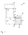
- Fig.1 schematically represents an engine cooling system 10 comprising a heat exchanger 12 according to the invention.
- Such an engine cooling system comprises an engine 14, generally an internal combustion engine. From an outlet side 16 of the engine 14, coolant is led to an inlet port 18 of the heat exchanger 12 via a feed line 20 and into the heat exchanger 12, generally a radiator, where the coolant is cooled. The cooled coolant is then fed back through an outlet port 22 of the heat exchanger 12 to an inlet side 24 of the engine via a return line 26.
- the coolant in the coolant circuit is below the optimal working temperature. In order to reach the optimal working temperature more quickly, it is preferred not to have the coolant cooled down by flowing through the heat exchanger 12.
- a flow control valve 28 is therefore arranged in the inlet port 18 of the heat exchanger 12 for returning the coolant directly to the inlet side 24 of the engine via a bypass line 30, thereby bypassing the heat exchanger 12.
- the heat exchanger 12 comprises a first elongate header tank 32 and a second elongate header tank 34 arranged parallel to the first header tank 32.
- the header tanks 32, 34 are in fluid communication with each other via a plurality of flow tubes 36 extending therebetween.
- the inlet port 18 for receiving the coolant coming from the outlet side 16 of the engine 14 is arranged in the first header tank 32.
- the outlet port 18 for feeding the coolant back to the engine 14 is arranged in either the first or second header tank 32, 34, depending on the header tank configuration.
- Corrugated fins 38 are generally arranged between individual flow tubes 36 in order to improve the heat transfer between the coolant in the flow tubes 36 and the air passing through the heat exchanger 12.
- a first embodiment of the invention is shown in Fig.2 and 3, wherein the heat exchanger is of the U-flow type.
- the heat exchanger comprises a first, vertically oriented, header tank 32, a second, vertically oriented, header tank 34, and regularly spaced pairs of flow tubes, two of which are shown at 36.
- the pairs of flow tubes 36 are separated by conventional, corrugated, air cooling fins 38, brazed in place. External air flow across the outside of the flow tubes 36 is in the direction shown by wavy arrow 40.
- the first header tank 32 comprises a flow control valve 28 having a valve body 39 forming one piece with the tank wall 41 of the first header tank 32.
- the coolant flow pattern is determined by a dividing wall 42 that runs the length of the inside of the first header tank 32, mating in sealed fashion to the inside of a header plate 44 to divide a tank chamber 46 of the first header tank 32 into a front, inlet side 48 and a rear, outlet side 50.
- the rear "half" of the heat exchanger 12 sees the hottest coolant as well as the hottest air flow (air which has already flowed over the front "half" of the heat exchanger 12) while the front "half" of the heat exchanger 12 (the front set of flow tubes 36), in which the coolant flow has already been partially cooled sees the coolest air flow.
- This provides the most thermally efficient pattern of air-coolant temperature differentials, and is inherently more efficient than a single flow heat exchanger.
- the invention works in conjunction with this internal structure of the first header tank 32 to provide an improved flow control valve 28, so as to take even more advantage of the inherent thermal efficiency advantage of the U-flow pattern.
- the coolant inlet port 18 of the first header tank 32 is, to all external appearances, a conventional, hollow cylindrical stub pipe to which a coolant hose can be clamped.
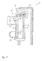
- the valve body 39 of the flow control valve 28 is formed by a hollow cylindrical barrel extending through one tank wall 41 of the first header tank 32, across and through the entire width of the first header tank 32, protruding slightly at the opposed tank wall 41 (as best seen in Fig.4), but which is open to the exterior of the first header tank 32 only at the stub pipe portion.
- the stub pipe is, in effect, the exterior protrusion of the valve body 39.
- the valve body 39 is in one piece with the tank wall 41 of the first header tank 32.
- the valve body 39 in and of itself, being essentially just an extension of the hollow cylindrical stub pipe, does not add any additional pressure drop, but, in the absence of other provisions, does also not allow any coolant inflow. However, additional structural features, described below, allow the valve body 39 to provide both an inlet and part of a coolant flow control valve 28.
- the outlet port 22 is open only to the outlet side 50 of the first header tank 32.
- the outlet port 22 can be configured as a pump housing containing e.g. an electric pump (not shown), but the invention here is not limited to use of an electric pump only.
- Such a pump can be used to power the coolant flow so that, as the coolant is pumped out of the outlet side 50 of the first header tank 32 and into the engine 14, coolant is pulled out of the engine 14 and into the inlet port 18 of the first header tank 32, where its flow path within the heat exchanger 12 is again is determined by the flow control valve 28 described next.
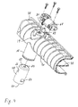
- the valve body 39 has a first cut-out 54 and a second cut-out 56, each generally rectangular in a planar, projected view, and one located on either side of the dividing wall 42, so as to open to the interior of the first header tank 32 in its inlet and outlet sides 48 and 50 respectively.
- a hollow cylindrical sleeve 58 with an open end 60, a closed end 62, and relatively thin wall through which a pair of axially spaced, diametrically opposed first and second windows 64, 66 are cut, also generally "rectangular".
- the windows 64, 66 are located near the open end 60 and closed end 62 respectively.
- the hollow cylindrical sleeve 58 is inserted into the valve body 39 until its closed end 62 abuts with the protruding end of valve body 39 and its open end 60 faces and is concentric to the inlet port 18.
- the sleeve's outer surface fits closely and turnably within the inner surface of the valve body 39, and is maintained co extensive and co axial with the valve body 39 when it is either rotated or moved axially back and forth.
- the thin wall of the sleeve 58 reduces the inner diameter of the valve body 39 only slightly, and it becomes, in effect, almost an extension of the inlet port 18 inserted within the valve body 39.
- a rotary type actuator 68 is mounted at the opposed outer wall of the first header tank 32.
- the actuator 68 has an electric motor that turns a splined shaft 70.
- the splined shaft 70 enters a through hole 72 in the back of the valve body 39 and is inserted non turnably into a closed ended hole 74 in the closed end 62 of the sleeve 58.
- a suitable seal surrounds the splined shaft 70 so as to prevent any leakage out of the valve body 39.
- the sleeve 58 turned within the valve body 39 by the actuator 68, provides an improved coolant flow within heat exchanger 12, as described next.
- the actuator 68 based on a temperature signal or other indication of the warm up condition, turns the sleeve 58 within the valve body 39 to a position wherein the first cut-out 54 is completely blocked by the wall of the sleeve 58, while the second window 66 and the second cut-out 56 are fully registered and aligned. Coolant flows out of the sleeve 58 only through the second window 66 into the outlet side 50 of first header tank 32. From there, it flows directly to the outlet port 22 and out of the first header tank 32, without ever flowing through the flow tubes 36 of the heat exchanger 12. The flow tubes 36 are hence bypassed and the coolant is not cooled.
- the engine is able to warm up quickly. Coolant flowing inside of the sleeve 58, and then turning 90 degrees to enter the outlet side 50 of the first header tank 32, does not undergo significantly more pressure drop than it would by just flowing through the inlet port 22 and into the interior of a regular header tank.
- the sleeve 58 uniquely cooperates with the valve body 39 to create the valving action at essentially no cost to performance. Benefits not only include the more rapid engine warm-up, but also a pre warming of the first header tank 32 to reduce thermal stress later. As disclosed, the inlet side 48 becomes fully blocked only as the outlet side 50 becomes fully opened.
- the shape and orientation of the second window 66 could be changed so that the first cut-out 54 remained blocked by the sleeve 58 as the second window 66 registered progressively more or less with the second cut-out 56, so as to meter and regulate the degree of the bypass flow.
- the actuator 68 turns the sleeve 58 within the valve body 39 until each window 64, 66 is registered partially with a respective cut-out 54, 56.
- This allows some coolant flow into inlet side 48 of the first header tank 32, and some into the outlet side 50 of the first header tank 32.
- the coolant flowing into the inlet side 48 flows through one row of flow tubes 36, into the second header tank 34 and back through the other row of flow tubes 36 and into the outlet side 50, rejecting heat to the air flow in the process.
- the sleeve 58 is turned so as to fully block the second cut-out 28 in the outlet side 50, and to fully register the first window 64 with the first cut-out 26 in the inlet side 48. Now, all flow runs through the flow tubes 36 and back, and none is bypassed, for maximum cooling capacity.
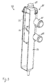
- valve body 39 is arranged in a direction perpendicular to the axial direction of the first header tank 32
- valve body 39 is arranged in a direction parallel to the axial direction of the first header tank 32.
- the valve body 39 of the flow control valve 28 is again formed by a hollow cylindrical barrel and forms one piece with the tank wall 41 of the first header tank 32, and is preferably integrally formed therewith.
- the flow control valve 28 can be more closely described by referring to Fig.9.
- the flow control valve 28 comprises a coaxially arranged hollow cylindrical sleeve 58.
- the valve body 39 comprises a first valve outlet port formed by a first cut-out 54 in the valve body 39 and a first window 64 (not visible in Fig.9) in the sleeve 58.
- a first window 64 and the first cut-out 54 are at least partially registered and aligned, a fluid communication between the interior of the sleeve 58 and the tank chamber of the first header tank 32 is formed.
- the valve body 39 further comprises a second valve outlet port formed by a second cut-out 56 in the valve body 39 and a second window 66 in the sleeve 58.
- a fluid communication between the interior of the sleeve 58 and the bypass channel is formed.
- the second valve outlet port comprises a bypass stub pipe 82 to which a hose connecting the inlet side 24 of the engine to the second valve outlet port can be clamped.
- valve body 39 comprises a valve inlet port formed by a third cut-out 76 in the valve body 39 and a third window 78 in the sleeve 58.
- a fluid communication between the interior of the sleeve 58 and the feed line 20 is formed. Coolant can then flow into the interior of the sleeve 58.
- the valve inlet port comprises an inlet stub pipe 80 to which a hose connecting the outlet side 16 of the engine to the valve inlet port can be clamped. When the valve inlet port is fully blocked, coolant does no longer circulate in the cooling system and the coolant more rapidly heats up.
- the flow control valve 28 further comprises an actuator 68 for rotating the sleeve 58 within the valve body 39.
- the first, second and third windows 64, 66, 78 are arranged in the sleeve 58 in such a way as to regulate the flow of coolant from the valve inlet port to the first and second outlet ports. Different operating modes of the engine cooling system are hence possible.
- Fig.10 shows in (a) a schematic representation of the flow control valve 28 and in (b) to (g), each time a cut through lines A-A, B-B and C-C in respective operating modes.
- the rightmost representation corresponds to the valve inlet port
- the central representation corresponds to the first valve outlet port opening into the heat exchanger circuit
- the leftmost representation corresponds to the second valve outlet port opening into the bypass circuit.
- the sleeve 58 is in a position wherein the valve inlet port is fully blocked, i.e. no coolant can flow into the flow control valve 28.
- the flow of coolant through the engine cooling system 10 is stopped and the coolant is allowed to quickly reach a working temperature.
- the actuator 68 is operated to rotate the sleeve 58 to a position as shown in (c) wherein the valve inlet port is partially open and the second valve outlet port partially open. Coolant is now allowed to flow from the feed line 20 to the bypass line 30. The first outlet port is fully blocked and no coolant can flow through the flow tubes 36 of the heat exchanger 12.
- the engine cooling system 10 operated in bypass mode. As the valve inlet port and the second valve outlet port are only partially open, the flow of coolant through the engine cooling system 10 is still restricted.
- the sleeve 58 is shown in a position wherein the valve inlet port and the second valve outlet port are fully open and the first outlet port is still fully blocked.
- the engine cooling system 10 still operates in bypass mode, but the flow of coolant through the engine cooling system 10 is no longer restricted.
- the sleeve 58 When the coolant temperature reaches a temperature where it becomes necessary to cool the coolant, the sleeve 58 is further rotated into a position, as shown in (e), wherein the first outlet port is at least partially open, so that some of the coolant can flow through the flow tubes 36 of the heat exchanger 12 and be cooled.
- the second valve outlet port is still fully open, so that the majority of the coolant still bypasses the flow tubes 36.
- the sleeve 58 is rotated into a position, as shown in (f), wherein the first outlet port is further opened and the second outlet port is partially blocked. The majority of the coolant now flows through the flow tubes 36 and is cooled by the heat exchanger 12.
- the sleeve 58 is shown in a position wherein the first valve outlet port is fully open and the second valve outlet port is fully closed. All of the coolant is now directed through the flow tubes 36 of the heat exchanger 12 and the maximum cooling effect is achieved.
- the actuator 68 can be brought into a "safe position" as shown in (g) by means of a spring (not illustrated) arranged between the sleeve 58 and the valve body 39 in case of an actuator failure. It can thereby be ensured that, if the actuator fails, the coolant is not allowed to exceed a maximum allowable temperature.
- one or more additional sleeves 84 can be coaxially arranged within the sleeve 58.
- the first valve outlet port is now formed by the first cut-out 54 in the valve body 39, the first window 64 (not visible in Fig.11) in the sleeve 58 and a first opening 86 (not visible in Fig.11) in the additional sleeve 84.
- first window 64, the first cut-out 54 and the first opening 86 are at least partially registered and aligned, a fluid communication between the interior of the additional sleeve 84 and the tank chamber 46 of the first header tank 32 is formed.
- the second valve outlet port is now formed by the second cut-out 56 in the valve body 39, a second window 66 of the sleeve 58 and a second opening 88 in the additional sleeve 84.
- a fluid communication between the interior of the additional sleeve 84 and the bypass line 30 is formed.
- valve inlet port is now formed by the third cut-out 76 in the valve body 39, the third window 78 of the sleeve 58 and a third opening 90 in the additional sleeve 84.
- the third window 66, the third cut-out 56 and the third opening 90 are at least partially registered and aligned, a fluid communication between the interior of the additional sleeve 84 and the feed line 20 is formed.
- the flow control valve 28 shown in Fig.11 comprises a single actuator 68 for rotating the sleeve 58 within the valve body 39 and the additional sleeve 84 within the sleeve 58.
- the actuator 68 drives the additional sleeve 84, which in turn drives the sleeve 58 when the two sleeves 58, 84 are in engagement.
- the two sleeves 58, 84 engage or disengage at a particular position of the sleeves. It is however not excluded to provide two actuators, one for driving the sleeve 58 and one for driving the additional sleeve 84.
- the actuator 68 comprises a splined shaft 70 engaging the additional sleeve 84, thereby rotating the latter by rotation of the splined shaft 70.
- the additional sleeve 84 comprises a snap element 92, which engages a recess 94 in the sleeve 84, so that the two sleeves 58, 84 are in engagement.
- the sleeve 58 is also rotated.
- the snap element 92 meets a protrusion 96, which pushes the snap element 92 out of engagement with the recess 94, thereby freeing the sleeve 58 from the additional sleeve 84. Further rotation of the additional sleeve 84 does now not drive the sleeve 58, which is now left behind.
Landscapes
- Engineering & Computer Science (AREA)
- Physics & Mathematics (AREA)
- Thermal Sciences (AREA)
- Mechanical Engineering (AREA)
- General Engineering & Computer Science (AREA)
- Heat-Exchange Devices With Radiators And Conduit Assemblies (AREA)
- Details Of Heat-Exchange And Heat-Transfer (AREA)
- Separation By Low-Temperature Treatments (AREA)
Applications Claiming Priority (2)
| Application Number | Priority Date | Filing Date | Title |
|---|---|---|---|
| US339525 | 1994-11-15 | ||
| US10/339,525 US6799631B2 (en) | 2003-01-09 | 2003-01-09 | Heat exchanger with integrated flow control valve |
Publications (3)
| Publication Number | Publication Date |
|---|---|
| EP1439366A2 true EP1439366A2 (de) | 2004-07-21 |
| EP1439366A3 EP1439366A3 (de) | 2006-12-27 |
| EP1439366B1 EP1439366B1 (de) | 2009-07-08 |
Family
ID=32594814
Family Applications (1)
| Application Number | Title | Priority Date | Filing Date |
|---|---|---|---|
| EP20030103730 Expired - Lifetime EP1439366B1 (de) | 2003-01-09 | 2003-10-08 | Wärmetauscher |
Country Status (4)
| Country | Link |
|---|---|
| US (2) | US6799631B2 (de) |
| EP (1) | EP1439366B1 (de) |
| AT (1) | ATE436001T1 (de) |
| DE (1) | DE60328257D1 (de) |
Cited By (3)
| Publication number | Priority date | Publication date | Assignee | Title |
|---|---|---|---|---|
| WO2006042680A1 (de) * | 2004-10-14 | 2006-04-27 | Behr Gmbh & Co. Kg | Wärmeübertrager, insbesondere kühimittelkühler für kraftfahrzeuge |
| EP1936316A1 (de) * | 2006-12-21 | 2008-06-25 | Nissan Motor Manufacturing (UK) Ltd. | Verbesserungen bei oder in Zusammenhang mit Kühlwasserkästen |
| US20100126692A1 (en) * | 2008-11-21 | 2010-05-27 | Hyundai Motor Company | Integrated hybrid heat exchanger with multi-sectional structure |
Families Citing this family (28)
| Publication number | Priority date | Publication date | Assignee | Title |
|---|---|---|---|---|
| US6799631B2 (en) * | 2003-01-09 | 2004-10-05 | Delphi Technologies, Inc. | Heat exchanger with integrated flow control valve |
| US7275394B2 (en) * | 2005-04-22 | 2007-10-02 | Visteon Global Technologies, Inc. | Heat exchanger having a distributer plate |
| EP2021666B8 (de) * | 2006-05-15 | 2018-01-03 | Thomas J. Hollis | Digitales drehstellventil |
| US7690397B2 (en) * | 2006-05-15 | 2010-04-06 | Hollis Thomas J | Digital rotary control valve |
| US8690072B2 (en) | 2007-04-03 | 2014-04-08 | Dana Canada Corporation | Radiator bypass valve |
| US7721973B2 (en) | 2007-04-03 | 2010-05-25 | Dana Canada Corporation | Valve |
| US20080289793A1 (en) * | 2007-05-22 | 2008-11-27 | Gerald Geiken | Thermal energy storage systems and methods |
| WO2009012311A2 (en) * | 2007-07-17 | 2009-01-22 | Jiffy-Tite Co., Inc. | Cooler bypass apparatus |
| US8166776B2 (en) * | 2007-07-27 | 2012-05-01 | Johnson Controls Technology Company | Multichannel heat exchanger |
| US8418931B2 (en) * | 2008-04-29 | 2013-04-16 | Ford Global Technologies, Llc | Heat exchanger with integral thermostats |
| IL192499A (en) * | 2008-06-29 | 2013-03-24 | S E S Solar Energy Solutions Ltd | Solar collector |
| US8919425B2 (en) * | 2008-09-02 | 2014-12-30 | Halla Visteon Climate Control Corporation | Flow control valve and heat exchanger equipped with same |
| EP2226538B1 (de) * | 2009-03-04 | 2017-01-04 | Jiffy-Tite CO., INC. | Rückschlagventil mit Modulation und / oder Antischwingungsfunktion |
| US8215381B2 (en) * | 2009-04-10 | 2012-07-10 | Ford Global Technologies, Llc | Method for controlling heat exchanger fluid flow |
| US8978992B2 (en) * | 2009-09-14 | 2015-03-17 | Jiffy-Tite Company, Inc. | Cooler bypass apparatus and installation kit |
| US8439104B2 (en) * | 2009-10-16 | 2013-05-14 | Johnson Controls Technology Company | Multichannel heat exchanger with improved flow distribution |
| KR101230990B1 (ko) | 2010-09-13 | 2013-02-07 | 기아자동차주식회사 | 라디에이터 일체형 3웨이밸브 |
| KR101219812B1 (ko) * | 2010-12-07 | 2013-01-09 | 기아자동차주식회사 | 자동차용 인터쿨러 제어방법 및 자동차 냉각 시스템 |
| US9239195B2 (en) * | 2011-04-26 | 2016-01-19 | Hyundai Motor Company | Heat exchanger for vehicle |
| US8991339B2 (en) | 2012-03-30 | 2015-03-31 | Ford Global Technologies, Llc | Multi-zone vehicle radiators |
| US9945623B2 (en) | 2012-05-31 | 2018-04-17 | Dana Canada Corporation | Heat exchanger assemblies with integrated valve |
| EP2960609B1 (de) * | 2014-06-26 | 2022-10-05 | Valeo Autosystemy SP. Z.O.O. | Verteiler, insbesondere zur verwendung in einem kühler eines kühlsystems |
| KR101703603B1 (ko) * | 2015-06-15 | 2017-02-07 | 현대자동차 주식회사 | 캔형 열교환기 |
| US11098966B2 (en) * | 2018-08-08 | 2021-08-24 | Denso International America, Inc. | Header tank for heat exchanger |
| US10900557B2 (en) | 2018-11-13 | 2021-01-26 | Dana Canada Corporation | Heat exchanger assembly with integrated valve with pressure relief feature for hot and cold fluids |
| CN109813145A (zh) * | 2019-03-25 | 2019-05-28 | 河北凯祥采暖设备有限公司 | 一种新型散热器 |
| US11635015B2 (en) | 2019-11-05 | 2023-04-25 | Norgren Gt Development Llc | Coolant control valve |
| CN114111422A (zh) * | 2021-12-03 | 2022-03-01 | 中国航空工业集团公司金城南京机电液压工程研究中心 | 一种封头集成换热多股流换热器 |
Family Cites Families (21)
| Publication number | Priority date | Publication date | Assignee | Title |
|---|---|---|---|---|
| US2650767A (en) * | 1941-06-06 | 1953-09-01 | Gen Motors Corp | Valve for lubricant temperature regulating systems |
| US3353590A (en) * | 1965-07-12 | 1967-11-21 | Holman And Moody Inc | Unitary oil filtering and cooling attachment for internal combustion engines |
| DE2614969A1 (de) * | 1976-04-07 | 1977-10-20 | Volkswagenwerk Ag | Anordnung mit einem motorkuehler eines fahrzeugs |
| US4169491A (en) * | 1977-11-18 | 1979-10-02 | Bajka Engineering Enterprises | Three port two-way diverter valve with integral drain on one output port |
| JPS5522504A (en) * | 1978-06-15 | 1980-02-18 | Nippon Denso Co Ltd | Heating apparatus employing hot water |
| FR2481791B1 (fr) | 1980-05-05 | 1985-11-22 | Ferodo Sa | Echangeur de chaleur, en particulier pour un circuit de refroidissement d'un moteur de vehicule automobile |
| EP0053003A1 (de) * | 1980-11-22 | 1982-06-02 | Imi Radiators Limited | Wärmeaustauscher |
| FR2602548B1 (fr) * | 1986-08-07 | 1990-07-27 | Valeo | Dispositif de vanne thermostatique pour circuit de refroidissement de moteur a combustion interne, et radiateur equipe d'un tel dispositif |
| FR2614095B1 (fr) * | 1987-04-16 | 1989-10-06 | Chausson Usines Sa | Echangeur de chaleur a faisceau tubulaire et a plusieurs passes |
| JP2875309B2 (ja) * | 1989-12-01 | 1999-03-31 | 株式会社日立製作所 | 空気調和装置とその装置に使用される熱交換器及び前記装置の制御方法 |
| FR2673241A1 (fr) | 1991-02-26 | 1992-08-28 | Valeo Thermique Moteur Sa | Radiateur de vehicule automobile muni d'un dispositif de commande de circulation de fluide. |
| JP3175242B2 (ja) | 1991-10-31 | 2001-06-11 | 株式会社デンソー | リンク固定装置 |
| DE4435693A1 (de) * | 1994-10-06 | 1996-04-11 | Behr Gmbh & Co | Zusatzheizungs-Anordnung |
| DE19507961A1 (de) * | 1995-03-07 | 1996-09-12 | Daimler Benz Ag | Brennkraftmaschine mit einem Abgasturbolader |
| US5979548A (en) * | 1996-12-23 | 1999-11-09 | Fafco, Inc. | Heat exchanger having heat exchange tubes with angled heat-exchange performance-improving indentations |
| US6161614A (en) * | 1998-03-27 | 2000-12-19 | Karmazin Products Corporation | Aluminum header construction |
| JP3552543B2 (ja) | 1998-07-29 | 2004-08-11 | 株式会社デンソー | 液冷式内燃機関の冷却装置 |
| US6019171A (en) | 1998-11-18 | 2000-02-01 | General Motors Corporation | Down flow, two pass radiator with automatic air venting means |
| DE10010078C2 (de) * | 2000-03-02 | 2003-06-18 | Bayerische Motoren Werke Ag | Kühlvorrichtung für ein flüssiges Betriebsmittel einer Brennkraftmaschine |
| US6471133B1 (en) * | 2001-10-08 | 2002-10-29 | Ford Global Technologies, Inc. | Combination radiator and thermostat assembly |
| US6799631B2 (en) * | 2003-01-09 | 2004-10-05 | Delphi Technologies, Inc. | Heat exchanger with integrated flow control valve |
-
2003
- 2003-01-09 US US10/339,525 patent/US6799631B2/en not_active Expired - Lifetime
- 2003-10-08 AT AT03103730T patent/ATE436001T1/de not_active IP Right Cessation
- 2003-10-08 EP EP20030103730 patent/EP1439366B1/de not_active Expired - Lifetime
- 2003-10-08 DE DE60328257T patent/DE60328257D1/de not_active Expired - Lifetime
-
2004
- 2004-09-23 US US10/948,074 patent/US20050034851A1/en not_active Abandoned
Cited By (5)
| Publication number | Priority date | Publication date | Assignee | Title |
|---|---|---|---|---|
| WO2006042680A1 (de) * | 2004-10-14 | 2006-04-27 | Behr Gmbh & Co. Kg | Wärmeübertrager, insbesondere kühimittelkühler für kraftfahrzeuge |
| US8210244B2 (en) | 2004-10-14 | 2012-07-03 | Behr Gmbh & Co. Kg | Heat exchanger, in particular radiator for motor vehicles |
| EP1936316A1 (de) * | 2006-12-21 | 2008-06-25 | Nissan Motor Manufacturing (UK) Ltd. | Verbesserungen bei oder in Zusammenhang mit Kühlwasserkästen |
| US20100126692A1 (en) * | 2008-11-21 | 2010-05-27 | Hyundai Motor Company | Integrated hybrid heat exchanger with multi-sectional structure |
| US8430069B2 (en) * | 2008-11-21 | 2013-04-30 | Hyundai Motor Company | Integrated hybrid heat exchanger with multi-sectional structure |
Also Published As
| Publication number | Publication date |
|---|---|
| DE60328257D1 (de) | 2009-08-20 |
| US20050034851A1 (en) | 2005-02-17 |
| EP1439366A3 (de) | 2006-12-27 |
| US20040134650A1 (en) | 2004-07-15 |
| US6799631B2 (en) | 2004-10-05 |
| EP1439366B1 (de) | 2009-07-08 |
| ATE436001T1 (de) | 2009-07-15 |
Similar Documents
| Publication | Publication Date | Title |
|---|---|---|
| EP1439366B1 (de) | Wärmetauscher | |
| JP5694712B2 (ja) | オイルクーラ | |
| EP1588034B1 (de) | Kühlkreislauf einer brennkraftmaschine mit niedertemperaturkühler | |
| EP1448877B1 (de) | Kühlmittelsteuerventil für fahrzeuge | |
| CN215445175U (zh) | 阀、车辆热管理系统以及车辆 | |
| US11268773B2 (en) | Dual heat exchangers with integrated diverter valve | |
| US5566881A (en) | Automotive hot-water Heating apparatus | |
| ES2266837T3 (es) | Bomba electrica para medio refrigerante con valvula integrada, asi como procedimiento para su control. | |
| US7237511B2 (en) | Cooling device of engine | |
| US8029248B2 (en) | Integrated coolant pumping module | |
| US20010042525A1 (en) | Control arrangement for a cooling circuit of an internal combustion engine | |
| US20050126517A1 (en) | Integrated heat exchange and fluid control device | |
| JP2005061417A (ja) | エンジン冷却用円板弁 | |
| CN106014591A (zh) | 用于控制分流式冷却系统的冷却剂流的控制装置 | |
| KR20230092845A (ko) | 차량용 냉각수 통합 열관리 장치 | |
| US20110259548A1 (en) | Heat exchanger and related method of manufacture | |
| DE102005032295A1 (de) | Durchsatzsteuerventil für Kraftmaschinenkühlwasser | |
| EP0969189B1 (de) | Totaler Kühlungszusammenbau für Kraftfahrzeuge, die mit Brennkraftmaschinen angetrieben werden | |
| US5042447A (en) | Thermostatically controlled fuel heater and cooler | |
| WO2019068192A1 (en) | ACTIVE WARMING SYSTEM AND METHOD | |
| EP0800943B1 (de) | Heizsystem für fahrzeuge | |
| EP1537307A1 (de) | Motork hlsysteme | |
| GB2090957A (en) | Heat exchanger | |
| EP4177448B1 (de) | Kühlsystem | |
| KR20200069138A (ko) | 워터 펌프 및 솔레노이드 밸브를 이용한 엔진의 냉각 시스템 |
Legal Events
| Date | Code | Title | Description |
|---|---|---|---|
| PUAI | Public reference made under article 153(3) epc to a published international application that has entered the european phase |
Free format text: ORIGINAL CODE: 0009012 |
|
| AK | Designated contracting states |
Kind code of ref document: A2 Designated state(s): AT BE BG CH CY CZ DE DK EE ES FI FR GB GR HU IE IT LI LU MC NL PT RO SE SI SK TR |
|
| AX | Request for extension of the european patent |
Extension state: AL LT LV MK |
|
| PUAL | Search report despatched |
Free format text: ORIGINAL CODE: 0009013 |
|
| AK | Designated contracting states |
Kind code of ref document: A3 Designated state(s): AT BE BG CH CY CZ DE DK EE ES FI FR GB GR HU IE IT LI LU MC NL PT RO SE SI SK TR |
|
| AX | Request for extension of the european patent |
Extension state: AL LT LV MK |
|
| 17P | Request for examination filed |
Effective date: 20070503 |
|
| AKX | Designation fees paid |
Designated state(s): AT BE BG CH CY CZ DE DK EE ES FI FR GB GR HU IE IT LI LU MC NL PT RO SE SI SK TR |
|
| 17Q | First examination report despatched |
Effective date: 20080519 |
|
| GRAJ | Information related to disapproval of communication of intention to grant by the applicant or resumption of examination proceedings by the epo deleted |
Free format text: ORIGINAL CODE: EPIDOSDIGR1 |
|
| GRAP | Despatch of communication of intention to grant a patent |
Free format text: ORIGINAL CODE: EPIDOSNIGR1 |
|
| GRAS | Grant fee paid |
Free format text: ORIGINAL CODE: EPIDOSNIGR3 |
|
| GRAA | (expected) grant |
Free format text: ORIGINAL CODE: 0009210 |
|
| AK | Designated contracting states |
Kind code of ref document: B1 Designated state(s): AT BE BG CH CY CZ DE DK EE ES FI FR GB GR HU IE IT LI LU MC NL PT RO SE SI SK TR |
|
| REG | Reference to a national code |
Ref country code: GB Ref legal event code: FG4D |
|
| REG | Reference to a national code |
Ref country code: CH Ref legal event code: EP |
|
| REG | Reference to a national code |
Ref country code: IE Ref legal event code: FG4D |
|
| REF | Corresponds to: |
Ref document number: 60328257 Country of ref document: DE Date of ref document: 20090820 Kind code of ref document: P |
|
| PG25 | Lapsed in a contracting state [announced via postgrant information from national office to epo] |
Ref country code: SI Free format text: LAPSE BECAUSE OF FAILURE TO SUBMIT A TRANSLATION OF THE DESCRIPTION OR TO PAY THE FEE WITHIN THE PRESCRIBED TIME-LIMIT Effective date: 20090708 |
|
| NLV1 | Nl: lapsed or annulled due to failure to fulfill the requirements of art. 29p and 29m of the patents act | ||
| PG25 | Lapsed in a contracting state [announced via postgrant information from national office to epo] |
Ref country code: FI Free format text: LAPSE BECAUSE OF FAILURE TO SUBMIT A TRANSLATION OF THE DESCRIPTION OR TO PAY THE FEE WITHIN THE PRESCRIBED TIME-LIMIT Effective date: 20090708 Ref country code: AT Free format text: LAPSE BECAUSE OF FAILURE TO SUBMIT A TRANSLATION OF THE DESCRIPTION OR TO PAY THE FEE WITHIN THE PRESCRIBED TIME-LIMIT Effective date: 20090708 Ref country code: ES Free format text: LAPSE BECAUSE OF FAILURE TO SUBMIT A TRANSLATION OF THE DESCRIPTION OR TO PAY THE FEE WITHIN THE PRESCRIBED TIME-LIMIT Effective date: 20091019 |
|
| PG25 | Lapsed in a contracting state [announced via postgrant information from national office to epo] |
Ref country code: NL Free format text: LAPSE BECAUSE OF FAILURE TO SUBMIT A TRANSLATION OF THE DESCRIPTION OR TO PAY THE FEE WITHIN THE PRESCRIBED TIME-LIMIT Effective date: 20090708 |
|
| PG25 | Lapsed in a contracting state [announced via postgrant information from national office to epo] |
Ref country code: PT Free format text: LAPSE BECAUSE OF FAILURE TO SUBMIT A TRANSLATION OF THE DESCRIPTION OR TO PAY THE FEE WITHIN THE PRESCRIBED TIME-LIMIT Effective date: 20091109 Ref country code: BG Free format text: LAPSE BECAUSE OF FAILURE TO SUBMIT A TRANSLATION OF THE DESCRIPTION OR TO PAY THE FEE WITHIN THE PRESCRIBED TIME-LIMIT Effective date: 20091008 |
|
| PG25 | Lapsed in a contracting state [announced via postgrant information from national office to epo] |
Ref country code: EE Free format text: LAPSE BECAUSE OF FAILURE TO SUBMIT A TRANSLATION OF THE DESCRIPTION OR TO PAY THE FEE WITHIN THE PRESCRIBED TIME-LIMIT Effective date: 20090708 Ref country code: DK Free format text: LAPSE BECAUSE OF FAILURE TO SUBMIT A TRANSLATION OF THE DESCRIPTION OR TO PAY THE FEE WITHIN THE PRESCRIBED TIME-LIMIT Effective date: 20090708 Ref country code: RO Free format text: LAPSE BECAUSE OF FAILURE TO SUBMIT A TRANSLATION OF THE DESCRIPTION OR TO PAY THE FEE WITHIN THE PRESCRIBED TIME-LIMIT Effective date: 20090708 Ref country code: CZ Free format text: LAPSE BECAUSE OF FAILURE TO SUBMIT A TRANSLATION OF THE DESCRIPTION OR TO PAY THE FEE WITHIN THE PRESCRIBED TIME-LIMIT Effective date: 20090708 |
|
| PLBE | No opposition filed within time limit |
Free format text: ORIGINAL CODE: 0009261 |
|
| STAA | Information on the status of an ep patent application or granted ep patent |
Free format text: STATUS: NO OPPOSITION FILED WITHIN TIME LIMIT |
|
| PG25 | Lapsed in a contracting state [announced via postgrant information from national office to epo] |
Ref country code: SK Free format text: LAPSE BECAUSE OF FAILURE TO SUBMIT A TRANSLATION OF THE DESCRIPTION OR TO PAY THE FEE WITHIN THE PRESCRIBED TIME-LIMIT Effective date: 20090708 Ref country code: BE Free format text: LAPSE BECAUSE OF FAILURE TO SUBMIT A TRANSLATION OF THE DESCRIPTION OR TO PAY THE FEE WITHIN THE PRESCRIBED TIME-LIMIT Effective date: 20090708 Ref country code: MC Free format text: LAPSE BECAUSE OF NON-PAYMENT OF DUE FEES Effective date: 20091031 |
|
| REG | Reference to a national code |
Ref country code: CH Ref legal event code: PL |
|
| 26N | No opposition filed |
Effective date: 20100409 |
|
| REG | Reference to a national code |
Ref country code: FR Ref legal event code: ST Effective date: 20100630 |
|
| PG25 | Lapsed in a contracting state [announced via postgrant information from national office to epo] |
Ref country code: FR Free format text: LAPSE BECAUSE OF NON-PAYMENT OF DUE FEES Effective date: 20091102 |
|
| PG25 | Lapsed in a contracting state [announced via postgrant information from national office to epo] |
Ref country code: GR Free format text: LAPSE BECAUSE OF FAILURE TO SUBMIT A TRANSLATION OF THE DESCRIPTION OR TO PAY THE FEE WITHIN THE PRESCRIBED TIME-LIMIT Effective date: 20091009 Ref country code: LI Free format text: LAPSE BECAUSE OF NON-PAYMENT OF DUE FEES Effective date: 20091031 Ref country code: CH Free format text: LAPSE BECAUSE OF NON-PAYMENT OF DUE FEES Effective date: 20091031 Ref country code: IE Free format text: LAPSE BECAUSE OF NON-PAYMENT OF DUE FEES Effective date: 20091008 |
|
| PG25 | Lapsed in a contracting state [announced via postgrant information from national office to epo] |
Ref country code: GB Free format text: LAPSE BECAUSE OF NON-PAYMENT OF DUE FEES Effective date: 20091008 |
|
| PG25 | Lapsed in a contracting state [announced via postgrant information from national office to epo] |
Ref country code: IT Free format text: LAPSE BECAUSE OF FAILURE TO SUBMIT A TRANSLATION OF THE DESCRIPTION OR TO PAY THE FEE WITHIN THE PRESCRIBED TIME-LIMIT Effective date: 20090708 |
|
| PG25 | Lapsed in a contracting state [announced via postgrant information from national office to epo] |
Ref country code: LU Free format text: LAPSE BECAUSE OF NON-PAYMENT OF DUE FEES Effective date: 20091008 |
|
| PG25 | Lapsed in a contracting state [announced via postgrant information from national office to epo] |
Ref country code: HU Free format text: LAPSE BECAUSE OF FAILURE TO SUBMIT A TRANSLATION OF THE DESCRIPTION OR TO PAY THE FEE WITHIN THE PRESCRIBED TIME-LIMIT Effective date: 20100109 |
|
| PG25 | Lapsed in a contracting state [announced via postgrant information from national office to epo] |
Ref country code: TR Free format text: LAPSE BECAUSE OF FAILURE TO SUBMIT A TRANSLATION OF THE DESCRIPTION OR TO PAY THE FEE WITHIN THE PRESCRIBED TIME-LIMIT Effective date: 20090708 |
|
| PG25 | Lapsed in a contracting state [announced via postgrant information from national office to epo] |
Ref country code: CY Free format text: LAPSE BECAUSE OF FAILURE TO SUBMIT A TRANSLATION OF THE DESCRIPTION OR TO PAY THE FEE WITHIN THE PRESCRIBED TIME-LIMIT Effective date: 20090708 |
|
| PG25 | Lapsed in a contracting state [announced via postgrant information from national office to epo] |
Ref country code: SE Free format text: LAPSE BECAUSE OF FAILURE TO SUBMIT A TRANSLATION OF THE DESCRIPTION OR TO PAY THE FEE WITHIN THE PRESCRIBED TIME-LIMIT Effective date: 20090708 |
|
| REG | Reference to a national code |
Ref country code: DE Ref legal event code: R082 Ref document number: 60328257 Country of ref document: DE Representative=s name: BRP RENAUD UND PARTNER MBB, DE Ref country code: DE Ref legal event code: R081 Ref document number: 60328257 Country of ref document: DE Owner name: MAHLE INTERNATIONAL GMBH, DE Free format text: FORMER OWNER: DELPHI TECHNOLOGIES, INC., TROY, MICH., US Ref country code: DE Ref legal event code: R082 Ref document number: 60328257 Country of ref document: DE Representative=s name: BRP RENAUD UND PARTNER MBB RECHTSANWAELTE PATE, DE |
|
| PGFP | Annual fee paid to national office [announced via postgrant information from national office to epo] |
Ref country code: DE Payment date: 20211027 Year of fee payment: 19 |
|
| REG | Reference to a national code |
Ref country code: DE Ref legal event code: R119 Ref document number: 60328257 Country of ref document: DE |
|
| PG25 | Lapsed in a contracting state [announced via postgrant information from national office to epo] |
Ref country code: DE Free format text: LAPSE BECAUSE OF NON-PAYMENT OF DUE FEES Effective date: 20230503 |