EP4177448B1 - Kühlsystem - Google Patents
Kühlsystem Download PDFInfo
- Publication number
- EP4177448B1 EP4177448B1 EP21832767.4A EP21832767A EP4177448B1 EP 4177448 B1 EP4177448 B1 EP 4177448B1 EP 21832767 A EP21832767 A EP 21832767A EP 4177448 B1 EP4177448 B1 EP 4177448B1
- Authority
- EP
- European Patent Office
- Prior art keywords
- thermostat
- coolant
- passage
- motor
- internal combustion
- Prior art date
- Legal status (The legal status is an assumption and is not a legal conclusion. Google has not performed a legal analysis and makes no representation as to the accuracy of the status listed.)
- Active
Links
Images



Classifications
-
- F—MECHANICAL ENGINEERING; LIGHTING; HEATING; WEAPONS; BLASTING
- F01—MACHINES OR ENGINES IN GENERAL; ENGINE PLANTS IN GENERAL; STEAM ENGINES
- F01P—COOLING OF MACHINES OR ENGINES IN GENERAL; COOLING OF INTERNAL-COMBUSTION ENGINES
- F01P7/00—Controlling of coolant flow
- F01P7/14—Controlling of coolant flow the coolant being liquid
- F01P7/16—Controlling of coolant flow the coolant being liquid by thermostatic control
- F01P7/165—Controlling of coolant flow the coolant being liquid by thermostatic control characterised by systems with two or more loops
-
- F—MECHANICAL ENGINEERING; LIGHTING; HEATING; WEAPONS; BLASTING
- F01—MACHINES OR ENGINES IN GENERAL; ENGINE PLANTS IN GENERAL; STEAM ENGINES
- F01P—COOLING OF MACHINES OR ENGINES IN GENERAL; COOLING OF INTERNAL-COMBUSTION ENGINES
- F01P3/00—Liquid cooling
- F01P3/20—Cooling circuits not specific to a single part of engine or machine
-
- F—MECHANICAL ENGINEERING; LIGHTING; HEATING; WEAPONS; BLASTING
- F01—MACHINES OR ENGINES IN GENERAL; ENGINE PLANTS IN GENERAL; STEAM ENGINES
- F01P—COOLING OF MACHINES OR ENGINES IN GENERAL; COOLING OF INTERNAL-COMBUSTION ENGINES
- F01P7/00—Controlling of coolant flow
- F01P7/14—Controlling of coolant flow the coolant being liquid
- F01P7/16—Controlling of coolant flow the coolant being liquid by thermostatic control
- F01P7/161—Controlling of coolant flow the coolant being liquid by thermostatic control by bypassing pumps
-
- F—MECHANICAL ENGINEERING; LIGHTING; HEATING; WEAPONS; BLASTING
- F01—MACHINES OR ENGINES IN GENERAL; ENGINE PLANTS IN GENERAL; STEAM ENGINES
- F01P—COOLING OF MACHINES OR ENGINES IN GENERAL; COOLING OF INTERNAL-COMBUSTION ENGINES
- F01P2060/00—Cooling circuits using auxiliaries
- F01P2060/16—Outlet manifold
Definitions
- This invention relates to a cooling system for an internal combustion engine.
- the conventional cooling system for internal combustion engines is equipped with motor-operated valves to distribute the coolant cooling the internal combustion engines to various devices such as the radiator, air-heating heat exchanger, automatic transmission AT/continuously variable transmission CVT, and exhaust gas recirculation EGR.
- thermo valve thermostat valve
- a safety function is used to prevent the internal combustion engine from overheating due to failing circulation of coolant to the radiator in the event of a failure (when a failure occurs).
- a patent literature PTL 1 discloses a cooling system equipped with a motor-operated valve having a thermo valve.
- the cooling system equipped with a motor-operated valve having a thermo valve recited in PTL 1 will be described based on Figs. 4 and 5 .
- a motor-operated valve 51 having a thermo valve is disposed on the side of the cylinder head CH of the internal combustion engine ENG.
- the motor-operated valve 51 having a thermo valve distributes the coolant, which is pressurized by water pump WP and passes through the cylinder head CH, to an air-heating heat exchanger HT, oil cooler OC and radiator RAD via a first piping L1 through a third piping L3, respectively, and controls each flow rate thereof.
- the motor-operated valve 51 having a thermo valve includes a reduction gear accommodated in a reduction gear housing 52, a valve body accommodated in a valve housing 53, and an electric motor accommodated in a motor housing 54, as shown in Fig. 5 .
- the rotation of the motor is reduced by the reduction gear, and the valve body is configured to rotate by the rotation shaft connected to the reduction gear.
- the motor is controlled by an electric control unit (ECU) and controls the rotation of the valve body via the reduction gear in response to the state of the vehicle.
- ECU electric control unit
- a first communicating port E1 of the motor-operated valve 51 having a thermo valve shown in Fig. 5 is connected to the piping L1 shown in Fig. 4 and communicates with the air-heating heat exchanger HT.
- a second communicating port E2 is connected to the second piping L2 and communicates with the oil cooler OC.
- a third communicating port E3 is connected to the third piping L3 and communicates with the radiator RAD.
- thermo valve as a failsafe mechanism is equipped at the third communicating port E3 and enables the valve housing 53 to communicate with the third communicating port E3 when the valve body cannot be driven due to failure or when the pressure or the temperature reaches the predetermined value.
- thermo valve as a failsafe mechanism, in the event of failure, opens when the coolant temperature rises to ensure the supply passage of the coolant to the radiator RAD and prevents the internal combustion engine ENG from overheating.
- a thermostat may be used to open and close the passage of the coolant.
- a thermostat with a jiggle valve for air bleeding recited in patent literature PTL 2 is generally used.
- the thermostat with a jiggle valve for air bleeding opens and closes the coolant passage in response to the coolant temperature. While the jiggle valve for air bleeding operates to let the air bleed from the coolant passage therethrough even when the thermostat is closed.
- FR 3 042 221 A1 discloses features falling under the preamble of claim 1.
- EP 3 163 046 B1 , WO 2016/084386 A1 , US 2018/347448 A1 , and EP 2 743 474 B1 are further prior art.
- the motor-operated valve has two main functions if roughly categorized: one is a cooling function to cool the internal combustion engine, and the other is a distributing function of the coolant to various devices such as the air-heating heat exchanger, automatic transmission AT/continuously variable transmission CVT, and exhaust gas recirculation EGR.
- the thermo valve as a fail-safe mechanism and the motor-operated valve are provided in an integrated unit, which makes it larger in size, poorly mountable in a vehicle, and expensive.
- the jiggle valve for air bleeding is configured to be closed by the pressure of the coolant. Since the coolant leaks through the jiggle valve for air bleeding even with the thermostat closed when a thermostat with a jiggle valve for air bleeding is used, it is difficult to warm up the engine promptly by raising the coolant temperature rapidly during air-heating. Further, though the conventional motor-operated valve can vary the coolant temperature to the desired temperature immediately, a new problem arises that because response delay occurs compared to the motor-operated valves when a conventional thermostat is used by separating the function thereof, suppression of knocking at an early stage by lowering the coolant temperature rapidly when knocking occurs is difficult.
- the present invention is made to solve the above problem, and the object of the invention is to provide a cooling system capable of having an excellent on-vehicle mountability, bleeding the air in the coolant passage, air heating promptly by raising the coolant temperature rapidly during air-heating, and suppressing knocking at an early stage by lowering the coolant temperature rapidly when knocking occurs.
- the invention is defined by claim 1.
- the cooling system of the present invention allows the thermostat to open and close the main passages to circulate coolant passing through the radiator to the internal combustion engine and to stop the circulation of coolant passing through the radiator to the internal combustion engine. Further, the motor-operated valve opens and closes the auxiliary passage that circulates the coolant between the internal combustion engine and the heat exchanger and the thermostat-bypass passage (thermostat-bypass passage), whereby the coolant via the radiator bypasses the thermostat or the distribution of the coolant to the heat exchanger changes.
- the heat exchanger denotes devices to which the coolant is supplied, such as an air-heating heat exchanger, ATF (automatic transmission fluid) warmer (CVT (continuously variable transmission) oil warmer), EGR (exhaust gas recirculation), and a throttle body.
- ATF automatic transmission fluid
- CVT continuously variable transmission
- EGR exhaust gas recirculation
- a throttle body To bypass the thermostat means to bypass a portion that is opened or closed by the valve body of the thermostat.
- the thermostat opens and closes the main passage to circulate and stop circulating the coolant passing through the radiator to the internal combustion engine. Therefore, there is no need to provide a thermo valve as a fail-safe mechanism on the motor-operated valve. Namely, even when the motor-operated valve fails, overheating of the internal combustion engine ENG can be prevented because the thermostat opens and closes the main passage.
- thermo valve can be eliminated from the motor-operated valve.
- the motor-operated valve can be downsized because it only needs to be able to open and close only the auxiliary passage and the bypassing passage of the thermostat. The downsizing of the motor-operated valve can improve the on-vehicle mountability and reduce cost.
- the downsized motor-operated valve since there is no need to dispose the downsized motor-operated valve in the vicinity of the water pump of the engine, it may be disposed anywhere in the middle of the thermostat-bypass passage and the auxiliary passage.
- the motor-operated valve opens and closes the thermostat-bypass passage that bypasses the thermostat.
- opening the thermostat-bypass passage by the motor-operated valve allows the air in the coolant passage to bleed out via the thermostat-bypass passage.
- the above configuration can eliminate the jiggle pin from the thermostat, thus preventing coolant leakage from the jiggle pin. This achieves air heating promptly by raising the coolant temperature rapidly when air heating and achieves suppressing knocking at an early stage when knocking occurs by lowering the coolant temperature rapidly.
- thermostat of the cooling system may include a heater that heats the temperature sensing unit.
- the thermostat can be stably kept open by heating the temperature sensing part (temperature-sensitive part) with a heater, and thus, the temperature of the coolant can be maintained at a low temperature even during high-load traveling.
- the motor-operated valve may open the thermostat-bypass passage when the ignition switch to start the internal combustion engine is OFF.
- the air in the coolant flow passage can be bled out via the thermostat-bypass passage when the ignition switch is turned off and the internal combustion engine is stopped; therefore, even if the internal combustion engine stops before the coolant temperature reaches the valve-opening temperature of the thermostat, the bleeding of the air in the coolant flow passage can be achieved.
- the cooling system according to the present invention is provided with a control device for controlling the opening and closing of the motor-operated valve and may be constructed such that the control device closes the auxiliary passage and the thermostat-bypass passage by the motor-operated valve when determining that the internal combustion engine is in a warming-up operation, the control device, by the motor-operated valve, closes the thermostat-bypass passage and opens the auxiliary passage when determining that the warming-up operation is finished, and the control device opens the thermostat-bypass passage with the motor-operated valve even if determining that the warming-up operation is finished when determining that knocking occurs.
- the main passage is closed with the thermostat, and the auxiliary passage and thermostat-bypass passage are closed with the motor-operated valve when the warming-up operation of the internal combustion engine with low coolant temperature is conducted. Consequently, the flow of the coolant flow passage of the cooling system is stopped, and the temperature of the coolant rises rapidly to achieve air heating quickly. Further, when the warming-up operation is completed, the auxiliary passage opens, so that the thermostat can sense the temperature and open the valve. Further, when knocking occurs, the thermostat bypass passage opens, and accordingly, the temperature of the coolant is lowered rapidly and knocking is suppressed at an early stage.
- the present invention allows to obtain a cooling system and a control method thereof, in which excellent mountability is provided, the air in the coolant flow passage can be bled, the quick air-heating can be achieved by rapidly raising the coolant temperature during air-heating, and knocking can be suppressed at an early stage by lowering the coolant temperature rapidly when knocking occurs.
- a cooling system and a control method thereof of a first embodiment according to the present invention will be described on the basis of Fig. 1 and Fig. 2 .
- the coolant cools an internal combustion engine 2
- the coolant that is circulated between a water jacket 2a of the internal combustion engine 2 and a radiator 3 is also circulated through heat exchangers, such as an air-heating heat exchanger 4, an automatic transmission fluid ATF warmer 5 (or a continuously variable transmission CVT oil warmer), and an exhaust gas recirculation EGR 6, and utilized individually at each device.
- heat exchangers such as an air-heating heat exchanger 4, an automatic transmission fluid ATF warmer 5 (or a continuously variable transmission CVT oil warmer), and an exhaust gas recirculation EGR 6, and utilized individually at each device.
- the above-described heat exchangers are examples and the system is also usable in a throttle body.
- the cooling system 1 is provided with a thermostat 7 that opens and closes a main passage L1 through which the coolant is circulated between a water jacket 2a of the internal combustion engine 2 and a radiator 3, an auxiliary passage L2 that communicates with a chamber (a second chamber 7b) where a temperature sensing unit 7B8 of the thermostat 7 is housed and through which the coolant circulates between the water jacket 2a and the heat exchangers of the air-heating heat exchanger 4, the ATF warmer 5 or the CVT oil warmer, and the EGR 6 except for the radiator 3, and a motor-operated valve 8 for changing the distribution of the coolant provided to each heat exchanger by opening and closing the auxiliary passage L2.
- a thermostat 7 that opens and closes a main passage L1 through which the coolant is circulated between a water jacket 2a of the internal combustion engine 2 and a radiator 3, an auxiliary passage L2 that communicates with a chamber (a second chamber 7b) where a temperature sensing unit 7B8 of the thermostat 7 is housed and through which the
- the motor-operated valve 8 opens and closes a thermostat-bypass passage L3 bypassing the thermostat 7, while motor-operated valve 8 is opening the thermostat-bypass passage L3, the internal combustion engine 2 communicates with the radiator 3. With this, the coolant cooling the internal combustion engine 2 can circulate between the internal combustion engine 2 and the radiator 3 without passing through the thermostat 7.
- the cooling system 1 will be described below in detail.
- the cooling system 1 is provided with the main passage L1 through which the coolant circulates between the internal combustion engine 2 and the radiator 3, as shown in Fig. 1 .
- the main passage includes a first main passage L1a, a second main passage L1b, and a third main passage L1c.
- the first main passage L1a connects an outlet of the coolant of a water jacket 2a of the internal combustion engine 2 to a coolant inlet of the radiator 3, the second main passage L1b connects a coolant outlet of the radiator 3 to the thermostat 7, and the third main passage L1c connects the thermostat 7 to a suction port of a water pump 9.
- the coolant sucked from the third main passage L1c and discharged from the water pump 9 is delivered to the water jacket 2a.
- the coolant flows via the internal combustion engine 2 and the radiator 3 through the main passage L1.
- the thermostat 7 opens and closes the connecting portion of the second auxiliary passage L1b to the third auxiliary passage L1c in the main passage L1 depending on the temperature of the coolant.
- the coolant system 1 is provided with an auxiliary passage L2 through which coolant circulates between the internal combustion engine 2 and the air-heating heat exchanger 4, the ATF warmer 5 , or the CVT oil warmer, or the EGR 6.
- the auxiliary passage L2 in the present embodiment, is provided with a first auxiliary passage L2a, a second auxiliary passage L2b, a third auxiliary passage L2C, and a fourth auxiliary passage L2d.
- the first auxiliary passage L2a connects a coolant outlet of the water jacket 2a to each of the heat exchangers such as the air-heating heat exchanger 4, the ATF warmer 5 or the CVT oil warmer, and the EGR 6.
- the second auxiliary passage L2b connects each of the heat exchangers to the motor-operated valve 8, and the third auxiliary passage L2c connects the motor-operated valve 8 to the chamber (the second chamber 7b to be described later) in which the temperature sensing unit 7B8 of the thermostat 7 is provided.
- the fourth auxiliary passage L2d connects the second chamber 7b to the suction port of the water pump 9.
- the fourth auxiliary passage L2d and the third main passage L1c share a coolant pipeline. That is, the third main passage L1c is also connected to the second chamber 7b in which the temperature sensing unit 7B8 of the thermostat 7 is provided.
- the thermostat 7 allows or shuts the communication between the second main passage L1b and the third main passage L1c by sensing the surrounding temperature of the temperature sensing unit 7B8 in the second chamber 7b.
- the motor-operated valve 8 opens and closes the second auxiliary passage L2b which leads to each of the heat exchangers such as the air-heating heat exchanger 4, the ATF warmer 5 or the CVT oil warmer, and the EGR 6, whereby the distribution of the coolant supplied to each heat exchanger is varied.
- the cooling system 1 is provided with a thermostat-by-pass passage L3 through which the coolant circulates between the internal combustion engine 2 and the radiator 3 with bypassing the thermostat 7.
- the thermostat-bypass passage L3 is provided with an upper-stream side passage L3a connecting the midway of the second main passage L1b to the motor-operated valve 8 and a lower-stream side passage L3b connecting the motor-operated valve 8 to the midway of the third main passage L1c, in the present embodiment.
- the second main passage L1b is connected to the radiator 3, and the third main passage L1c is connected to the water pump 9. Because of this configuration, even in a state where the thermostat 7 closes the main passage L1, when the motor-operated valve 8 opens the thermostat-bypass passage L3, the coolant flowing from the water jacket 2a goes toward the water pump 9 by passing through the first main passage L1a, radiator 3, the second main passage L1b, the thermostat-bypass passage L3, and the third main passage L1c.
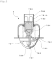
- the thermostat 7 is housed in a housing 7a, as shown in Fig. 1 .
- the interior of the housing 7a is partitioned into two chambers 7a and 7b by a valve body 7B1 of the thermostat 7, which will be described later. If one of the two chambers is designated as a first chamber 7a and the other as a second chamber 7b, the second main passage L1b is connected to the first chamber 7a, and the third main passage L1c is connected to the second chamber 7b.
- the thermostat 7 is provided with a thermo-element 7B2 as a temperature-sensitive actuator, a valve body 7B1 driven by the thermo-element 7B2 to unseat from or to seat on a valve seat 7B3 to open or close the main passage L1, a spring 7B4 as a biasing member to bias the valve body 7B1 in a direction to normally close (a direction to seat the valve body on the valve seat 7B3), and a cylindrical holder 7B9 to which the coolant from the third auxiliary passage L2c flows in.
- a thermo-element 7B2 as a temperature-sensitive actuator
- a valve body 7B1 driven by the thermo-element 7B2 to unseat from or to seat on a valve seat 7B3 to open or close the main passage L1
- a spring 7B4 as a biasing member to bias the valve body 7B1 in a direction to normally close (a direction to seat the valve body on the valve seat 7B3)
- a cylindrical holder 7B9 to which the coolant from
- thermo-element 7B2 is provided with a piston guide 7B5, a piston 7B7 whose tip end is engaged with a piston receiver 7B6, advancing and retracting while guided by the piston guide 7B5, and a temperature sensing unit (temperature-sensitive unit) 7B8 which incorporates wax as a thermal expander that makes the piston 7B7 advance and retract by expanding and contracting depending on the temperature variation of the coolant.
- a temperature sensing unit (temperature-sensitive unit) 7B8 which incorporates wax as a thermal expander that makes the piston 7B7 advance and retract by expanding and contracting depending on the temperature variation of the coolant.
- the holder 7B9 is disposed on the outer circumference of the temperature sensing unit 7B8, and the coolant coming from the third auxiliary passage L2c toward the fourth auxiliary passage L2d passes through the inside of the holder 7B9 and an opening 7B10 of the holder 7B9.
- thermostat 7 closes, the communication between the two chambers 7a and 7b is shut off, thereby shutting off the communication between the second main passage L1b and the third main passage L1c.
- thermostat Although an example of a thermostat is described here, the configuration of the thermostat can be appropriately changed.
- the temperature sensitivity of the thermostat 7 can be improved if the thermostat 7 is provided on the coolant inlet side of the internal combustion engine 2, but the holder 7B9 may be omitted.
- the thermostat 7 may also be equipped with an auxiliary valve to open and close the auxiliary passage L2 in addition to the valve element 7B1.
- the valve seat 7B3 is formed on the frame 7C including the piston receiver 7B6 of the thermostat 7 in the present embodiment.
- the housing 7A functions as a frame 7C and the valve seat 7B3 may be formed on the housing 7A.
- the holder 7B9 may integrally be formed with the housing 7A.
- the motor-operated valve 8 a typically-used one can be adopted.
- the motor-operated valve recited in PTL 1 from which the thermo valve as a fail-safe mechanism is removed may be used.
- An example of the motor-operated valve 8 will be described below.
- the motor-operated valve 8 is provided with a reduction gear housed in a reduction gear housing, a valve body housed in a valve body housing, and an electric motor housed in a motor housing.
- the motor-operated valve 8 is configured such that the valve body thereof is rotated (operated) by a rotation shaft connected to a reduction gear that reduces the rotation of the electric motor.
- a controller (ECU) mounted on a vehicle controls the electric motor and controls the rotation of the valve body (a rotary type valve body) through the reduction gear, according to the vehicle state.
- the second auxiliary passage L2b connected to each of the heat exchangers such as the heat exchanger 4 for heating, the automatic transmission fluid ATF warmer 5 (or continuously variable transmission CVT oil warmer), and the exhaust gas recirculation EGR 5 is opened and closed by driving the rotation of the valve body, so that the distribution of the coolant to the heat exchangers is changed.
- the valve body of the motor-operated valve 8 is not limited to a rotary type and may be a spool type valve body linearly movable. Further, direct opening and closing of a valve using a solenoid may be possible.
- the second auxiliary passage L2b is opened or closed by the motor-operated valve 8 through electronic control based on information from various sensors provided in the vehicle, or by the driver's selection. This allows the air-heating heat exchanger 4, the ATF 5, or CVT oil warmer, and the EGR 6 to be supplied or not supplied with the coolant.
- the thermostat-bypass passage L3 is opened or closed by the motor-operated valve 8, by electronic control based on information from various sensors provided in the vehicle, depending on the status of the internal combustion engine and the temperature of the coolant.
- the motor-operated valve 8 is in a de-energized state. In such a de-energized state, the motor-operated valve 8 is set to open the thermostat-bypass passage L3. With this setting, the air in the coolant passage can be bled through the thermostat-bypass passage L3, even when the temperature of the coolant is low and the thermostat 7 is closed.
- thermostat 7 it is needless to provide a jiggle pin for air bleeding in thermostat 7, and then the jiggle pin is omitted in thermostat 7. Namely, the air in the coolant passage can be bled even when a thermostat 7 without a jiggle valve for air bleeding is used.
- the control unit When the ignition is turned on, the control unit, after determining that the various electrical devices such as the electric valve 8 are operating normally, starts the internal combustion engine 2, and then starts warm-up operation. Further, when the control unit determines the warming-up operation is in process, the control unit outputs a command that the motor-operated valve 8 close the auxiliary passage L2 and close the thermostat-bypass passage L3.
- the determination of whether the warm-up operation is in the process may be performed using the temperature of the coolant detected by the temperature sensor or using the time elapsed from the start of the internal combustion engine 2. Accordingly, during the warming-up operation, the communication of the auxiliary passage L2 and of the thermostat-bypass passage L3 is cut off by the motor-operated valve 8.
- the temperature of the coolant is low, and the thermostat 7 is closed to cut off the communication of the main passage L1.
- the thermostat 7 is closed to cut off the communication of the main passage L1.
- the control unit determines that the warming-up operation of the internal combustion engine is completed, the control unit sends a command to the motor-operated valve 8 to close the thermostat-bypass passage L3 and to selectively open the second auxiliary passage L2b which is connected to each of the heat exchangers of the air-heating heat exchanger 4, the automatic transmission fluid ATF 5 (or continuously variable transmission CVT) oil warmer, and the exhaust gas recirculation EGR 6, depending on the temperature of the coolant.
- the control unit sends a command to the motor-operated valve 8 to close the thermostat-bypass passage L3 and to selectively open the second auxiliary passage L2b which is connected to each of the heat exchangers of the air-heating heat exchanger 4, the automatic transmission fluid ATF 5 (or continuously variable transmission CVT) oil warmer, and the exhaust gas recirculation EGR 6, depending on the temperature of the coolant.
- the thermostat 7 opens the main passage L1, and the coolant cooled by passing through the radiator 3 is supplied to the internal combustion engine 2 through the main passage L1.
- control unit may send a command to the motor-operated valve 8 to open the second auxiliary passage L2b that leads to the air-heating heat exchanger 4.
- the control unit determines that knocking occurs, even with the determination that the warming-up operation has been completed, the control unit sends a command that the motor-operated valve 8 should open the thermostat-bypass passage L3.
- the determination as to whether knocking is occurring may be made based on information from the knocking sensor or may be based on information detected by other sensors.
- Knocking occurs when the coolant temperature becomes high. This temperature rise of the coolant causes thermostat 7 to open the main passage L1, and further, by opening the thermostat-bypass passage L3 with the motor-operated valve 8, knocking can be suppressed at an early stage by lowering the coolant temperature quickly.
- the control unit may send a command to the motor-operated valve 8 to open the thermostat-bypass passage L3 and to close the auxiliary passage L2. Since this increases the flow rate of coolant flowing to the radiator 3, knocking can be suppressed at an earlier stage.
- thermo-element 7B2 for heating the temperature sensing unit 7B8 may be used as a thermostat 7.
- valve-opened state of the electronically-controlled thermostat can be maintained by heating the temperature sensing unit 7B8 with a heater.
- the temperature of the coolant can be maintained at a low temperature even in a traveling mode continuously highly loaded such as hill-climbing traveling.
- the thermostat 7, described in the first embodiment is installed on the coolant inlet side of the internal combustion engine 2, but it may be installed on the coolant outlet side of the internal combustion engine 2, as shown in Fig. 3 .
- Members identical or equivalent to those in the first embodiment have the same reference numbers, and the detailed descriptions will be omitted.
- the main passage L11 through which the coolant circulates between the internal combustion engine 2 and the radiator 3, is provided with a first main passage L11a, a second main passage L11b, and a third main passage L11c.
- the first main passage L11a connects the coolant outlet of the water jacket 2a of the internal combustion engine 2 to the thermostat 7
- the second main passage L11b connects the thermostat 7 to the coolant inlet of the radiator 3
- the third main passage L11c connects the coolant outlet of the radiator 3 to the suction inlet of the water pump 9.
- the coolant sucked from the third main passage L11c and discharged from the water pump 9 is delivered to the water jacket 2a.
- the coolant flows via the internal combustion engine 2 and the radiator 3 through the main passage L11.
- the thermostat 7 opens and closes the connecting portion of the first main passage L11a and the second main passage L11b in the main passage L11 depending on the temperature of the coolant.
- the cooling system 10 is provided with an auxiliary passage L12 through which the coolant circulates between the internal combustion engine 2 and the air-heating heat exchanger 4, the automatic transmission fluid ATF 5 (or continuously variable transmission CVT) oil warmer, and the exhaust gas recirculation EGR 6.
- the auxiliary passage L12 is provided with a first auxiliary passage L12a, a second auxiliary passage L12b, a third auxiliary passage L12c, and a fourth auxiliary passage L12d.
- the fourth auxiliary passage L12d connects each of the heat exchangers to the suction inlet of the water pump 9.
- the first auxiliary passage L12a shares piping with the first main passage L11a.
- the first main passage L11a is also connected to the second chamber 7b where the temperature sensing unit 7B8 of the thermostat 7 is located.
- the thermostat 7 senses the temperature around the temperature sensing unit 7B8 in the second chamber 7b and allows or shuts the communication between the first main passage L11a and the second main passage L11b.
- the motor-operated valve 8 opens and closes the third auxiliary passage L12c leading to each of the heat exchangers such as the air-heating heat exchanger 4, the ATF 5, or CVT oil warmer, and the EGR 6, whereby the distribution of coolant being supplied to each of the heat exchangers changes.
- the cooling system 10 is provided with a thermostat-bypass passage L13 through which the coolant circulates between the internal combustion engine 2 and the radiator 3 with bypassing the thermostat 7.
- the thermostat-bypass passage L13 connects the motor-operated valve 8 to a midway of the second main passage L11b.
- the second embodiment thus configured, similar to the first embodiment, is provided with the thermostat 7 and the motor-operated valve 8, the coolant cooling the internal combustion engine 2 is switched between cases of going through and bypassing the thermostat 7.
- the air in the coolant flow passage can be bled, the quick air-heating can be achieved by rapidly raising the coolant temperature during air-heating, and knocking can be suppressed at an early stage by lowering the coolant temperature rapidly when knocking occurs, whereby effects similar to those of the first embodiment are obtainable.
Landscapes
- Engineering & Computer Science (AREA)
- Chemical & Material Sciences (AREA)
- Combustion & Propulsion (AREA)
- Mechanical Engineering (AREA)
- General Engineering & Computer Science (AREA)
- Temperature-Responsive Valves (AREA)
- Exhaust-Gas Circulating Devices (AREA)
Claims (4)
- Kühlsystem (1), umfassend:einen Verbrennungsmotor (2);einen Kühler (3) zum Abstrahlen von Wärme von einem Kühlmittel zum Kühlen des Verbrennungsmotors (2);einen oder mehrere Wärmetauscher (4, 5, 6), die vom Kühler (3) unterschiedlich sind;einen Hauptdurchgang (L1, L11), durch den Kühlmittel zwischen dem Verbrennungsmotor (2) und dem Kühler (3) zirkulieren soll;einen Thermostat (7), der eine Temperaturerfassungseinheit zum Erfassen der Temperatur des Kühlmittels und zum Öffnen und Schließen des Hauptdurchgangs (L1, L11) abhängig von der Temperatur des Kühlmittels einschließt;einen Nebendurchgang (L2, L12), durch den das Kühlmittel zwischen dem Verbrennungsmotor (2) und dem einen oder den mehreren Wärmetauschern (4, 5, 6) über einen Raum (7b) zirkulieren soll, in dem die Temperaturerfassungseinheit angeordnet ist; undeinen Thermostat-Bypassdurchgang (L3, L13), der den Verbrennungsmotor (2) und den Kühler (3) durch Umgehen des Thermostats (7) in Kommunikation bringt; gekennzeichnet durchein motorbetriebenes Ventil (8), das so angeordnet ist, dass es den Nebendurchgang (L2, L12) und den Thermostat-Bypassdurchgang (L3, L13) öffnet und schließt.
- Kühlsystem (1) nach Anspruch 1, wobei der Thermostat (7) ein Heizelement einschließt, um die Temperaturerfassungseinheit zu erwärmen.
- Kühlsystem nach Anspruch 1 oder Anspruch 2, wobei das motorbetriebene Ventil (8) so angeordnet ist, dass es den Thermostat-Bypassdurchgang (L3, L13) mit einem Zündungsschalter zum Starten des Verbrennungsmotors (2), der sich in ausgeschaltetem Zustand befindet, öffnet.
- Kühlsystem nach einem der Ansprüche 1 bis 3, weiter umfassend:eine Steuervorrichtung zum Steuern des Öffnens und Schließens des motorbetriebenen Ventils (8), wobeidie Steuervorrichtung so angeordnet ist, dass sie den Nebendurchgang (L2, L12) und den Thermostat-Bypassdurchgang (L3, L13) mit dem motorbetriebenen Ventil (8) schließt, wenn sie bestimmt, dass sich der Verbrennungsmotor (2) in einem Aufwärmbetrieb befindet; die Steuervorrichtung mit dem motorbetriebenen Ventil (8) so angeordnet ist, dass sie den Thermostat-Bypassdurchgang (L3, L13) schließt und den Nebendurchgang (L2, L12) öffnet, wenn sie bestimmt, dass der Aufwärmbetrieb abgeschlossen ist; unddie Steuervorrichtung so angeordnet ist, dass sie den Thermostat-Bypassdurchgang (L3, L13) mit dem motorbetriebenen Ventil (8) selbst dann öffnet, wenn sie bestimmt, dass der Aufwärmbetrieb abgeschlossen ist, wenn sie bestimmt, dass Klopfen auftritt.
Applications Claiming Priority (2)
| Application Number | Priority Date | Filing Date | Title |
|---|---|---|---|
| JP2020114351A JP7488134B2 (ja) | 2020-07-01 | 2020-07-01 | 冷却システム |
| PCT/JP2021/016994 WO2022004115A1 (ja) | 2020-07-01 | 2021-04-28 | 冷却システム |
Publications (3)
| Publication Number | Publication Date |
|---|---|
| EP4177448A1 EP4177448A1 (de) | 2023-05-10 |
| EP4177448A4 EP4177448A4 (de) | 2024-07-31 |
| EP4177448B1 true EP4177448B1 (de) | 2025-05-28 |
Family
ID=79315269
Family Applications (1)
| Application Number | Title | Priority Date | Filing Date |
|---|---|---|---|
| EP21832767.4A Active EP4177448B1 (de) | 2020-07-01 | 2021-04-28 | Kühlsystem |
Country Status (6)
| Country | Link |
|---|---|
| US (1) | US11795861B2 (de) |
| EP (1) | EP4177448B1 (de) |
| JP (1) | JP7488134B2 (de) |
| CN (1) | CN115735049B (de) |
| TW (1) | TW202204762A (de) |
| WO (1) | WO2022004115A1 (de) |
Families Citing this family (1)
| Publication number | Priority date | Publication date | Assignee | Title |
|---|---|---|---|---|
| CN116753063B (zh) * | 2023-05-29 | 2026-03-17 | 广州汽车集团股份有限公司 | 发动机冷却系统用节温器及车辆 |
Family Cites Families (24)
| Publication number | Priority date | Publication date | Assignee | Title |
|---|---|---|---|---|
| JPS53146827U (de) | 1977-04-22 | 1978-11-18 | ||
| JPS6147425U (ja) * | 1984-09-01 | 1986-03-29 | マツダ株式会社 | エンジンの冷却水制御装置 |
| JPS61132431U (de) * | 1985-02-05 | 1986-08-19 | ||
| JP2551491Y2 (ja) * | 1992-06-05 | 1997-10-22 | 愛知機械工業株式会社 | 自動車用エンジンの水温制御構造 |
| JPH06272557A (ja) * | 1993-03-22 | 1994-09-27 | Nippondenso Co Ltd | 車両における内燃機関の冷却装置 |
| JP2002054440A (ja) * | 2000-08-10 | 2002-02-20 | Mitsubishi Motors Corp | 内燃機関の冷却制御装置 |
| KR100435946B1 (ko) * | 2001-04-19 | 2004-06-12 | 현대자동차주식회사 | 엔진의 냉각 시스템 |
| US6945200B2 (en) * | 2002-09-13 | 2005-09-20 | Volvo Construction Equipment Holding Sweden Ab | Cooling system for a vehicle and a vehicle comprising the cooling system |
| DE10335567A1 (de) * | 2003-07-31 | 2005-03-10 | Behr Gmbh & Co Kg | Kreislaufanordnung zur Kühlung von Ladeluft und Verfahren zum Betreiben einer derartigen Kreislaufanordnung |
| US7243620B2 (en) * | 2004-11-11 | 2007-07-17 | Denso Corporation | Liquid-cooling device for internal combustion engine |
| GB0426647D0 (en) * | 2004-12-04 | 2005-01-05 | Ford Global Tech Llc | An engine cooling system |
| JP4137063B2 (ja) * | 2005-01-19 | 2008-08-20 | 三菱電機株式会社 | 車両用動力源の冷却系制御装置 |
| DE102005048286B4 (de) * | 2005-10-08 | 2007-07-19 | Itw Automotive Products Gmbh & Co. Kg | Verfahren zum Betrieb eines Kühlsystems für eine Verbrennungskraftmaschine |
| DE102009036603B4 (de) * | 2009-07-30 | 2020-07-16 | Dr. Ing. H.C. F. Porsche Aktiengesellschaft | Kühlsystem für eine Brennkraftmaschine |
| JP5925456B2 (ja) * | 2011-09-22 | 2016-05-25 | 株式会社ミクニ | 冷却水制御バルブ装置 |
| US8689617B2 (en) * | 2012-03-30 | 2014-04-08 | Ford Global Technologies, Llc | Engine cooling system control |
| JP5993759B2 (ja) * | 2013-02-27 | 2016-09-14 | カルソニックカンセイ株式会社 | エンジンの吸気冷却装置 |
| EP2873826B1 (de) * | 2013-11-15 | 2019-03-27 | Volvo Car Corporation | Wärmespeicher in Motorkühlsystem |
| JP2016003578A (ja) * | 2014-06-13 | 2016-01-12 | トヨタ自動車株式会社 | エンジン冷却装置 |
| JP6287625B2 (ja) * | 2014-06-25 | 2018-03-07 | アイシン精機株式会社 | 内燃機関の冷却システム |
| US9481241B2 (en) * | 2014-09-30 | 2016-11-01 | Ford Global Technologies, Llc | Cooling system for a vehicle solar panel |
| JP6210054B2 (ja) * | 2014-11-28 | 2017-10-11 | トヨタ自動車株式会社 | 内燃機関の冷却システム |
| FR3042221B1 (fr) * | 2015-10-07 | 2019-09-27 | Psa Automobiles Sa. | Groupe motopropulseur comprenant un moteur thermique equipe d’un circuit de refroidissement et d’un echangeur thermique |
| JP6679324B2 (ja) | 2016-01-29 | 2020-04-15 | 日本サーモスタット株式会社 | フェールセーフ機構付弁装置 |
-
2020
- 2020-07-01 JP JP2020114351A patent/JP7488134B2/ja active Active
-
2021
- 2021-04-28 EP EP21832767.4A patent/EP4177448B1/de active Active
- 2021-04-28 WO PCT/JP2021/016994 patent/WO2022004115A1/ja not_active Ceased
- 2021-04-28 US US18/011,392 patent/US11795861B2/en active Active
- 2021-04-28 CN CN202180047132.8A patent/CN115735049B/zh active Active
- 2021-05-12 TW TW110117015A patent/TW202204762A/zh unknown
Also Published As
| Publication number | Publication date |
|---|---|
| CN115735049B (zh) | 2025-07-22 |
| CN115735049A (zh) | 2023-03-03 |
| TW202204762A (zh) | 2022-02-01 |
| EP4177448A1 (de) | 2023-05-10 |
| US20230265778A1 (en) | 2023-08-24 |
| JP2022012490A (ja) | 2022-01-17 |
| JP7488134B2 (ja) | 2024-05-21 |
| US11795861B2 (en) | 2023-10-24 |
| EP4177448A4 (de) | 2024-07-31 |
| WO2022004115A1 (ja) | 2022-01-06 |
Similar Documents
| Publication | Publication Date | Title |
|---|---|---|
| CN103291435B (zh) | 冷却水控制阀装置 | |
| US10023025B2 (en) | Heat management system for an internal combustion engine | |
| US10161361B2 (en) | Method for operating a coolant circuit | |
| US7124715B2 (en) | Engine cooling systems | |
| US8463495B2 (en) | Method for controlling exhaust gas heat recovery systems in vehicles | |
| US7263954B2 (en) | Internal combustion engine coolant flow | |
| US8944017B2 (en) | Powertrain cooling system with cooling and heating modes for heat exchangers | |
| EP1918545A2 (de) | Kühlmittelregler für einen Verbrennungsmotor | |
| US11105254B2 (en) | Cooling system and internal combustion engine | |
| US11085357B2 (en) | Method and device for ventilating a heat management system of an internal combustion engine | |
| US11248519B2 (en) | Active warm-up system and method | |
| EP4177448B1 (de) | Kühlsystem | |
| JP5853911B2 (ja) | 内燃機関の冷却装置 | |
| GB2394537A (en) | Engine cooling system with auxiliary heater mixer valve | |
| KR102478089B1 (ko) | 차량용 냉각시스템 제어방법 | |
| JP4292883B2 (ja) | エンジンの冷却装置 | |
| JP2010096138A (ja) | エンジンの冷却装置 | |
| JP3292217B2 (ja) | 車両用油温制御装置 | |
| JP2006057635A (ja) | 電動ウォーターポンプの取付け配列構成 | |
| JPH06193443A (ja) | エンジンの冷却装置 | |
| JP7661778B2 (ja) | エンジンの冷却システム | |
| KR101047752B1 (ko) | 유체의 열 교환용 밸브 | |
| JP2001280133A (ja) | 冷却水制御装置 | |
| JP2010096139A (ja) | エンジンの冷却装置 |
Legal Events
| Date | Code | Title | Description |
|---|---|---|---|
| STAA | Information on the status of an ep patent application or granted ep patent |
Free format text: STATUS: THE INTERNATIONAL PUBLICATION HAS BEEN MADE |
|
| PUAI | Public reference made under article 153(3) epc to a published international application that has entered the european phase |
Free format text: ORIGINAL CODE: 0009012 |
|
| STAA | Information on the status of an ep patent application or granted ep patent |
Free format text: STATUS: REQUEST FOR EXAMINATION WAS MADE |
|
| 17P | Request for examination filed |
Effective date: 20230123 |
|
| AK | Designated contracting states |
Kind code of ref document: A1 Designated state(s): AL AT BE BG CH CY CZ DE DK EE ES FI FR GB GR HR HU IE IS IT LI LT LU LV MC MK MT NL NO PL PT RO RS SE SI SK SM TR |
|
| DAV | Request for validation of the european patent (deleted) | ||
| DAX | Request for extension of the european patent (deleted) | ||
| A4 | Supplementary search report drawn up and despatched |
Effective date: 20240701 |
|
| RIC1 | Information provided on ipc code assigned before grant |
Ipc: F01P 3/20 20060101ALI20240625BHEP Ipc: F01P 7/16 20060101AFI20240625BHEP |
|
| GRAP | Despatch of communication of intention to grant a patent |
Free format text: ORIGINAL CODE: EPIDOSNIGR1 |
|
| STAA | Information on the status of an ep patent application or granted ep patent |
Free format text: STATUS: GRANT OF PATENT IS INTENDED |
|
| INTG | Intention to grant announced |
Effective date: 20250103 |
|
| GRAS | Grant fee paid |
Free format text: ORIGINAL CODE: EPIDOSNIGR3 |
|
| GRAA | (expected) grant |
Free format text: ORIGINAL CODE: 0009210 |
|
| STAA | Information on the status of an ep patent application or granted ep patent |
Free format text: STATUS: THE PATENT HAS BEEN GRANTED |
|
| RIN1 | Information on inventor provided before grant (corrected) |
Inventor name: SUDA, HIROSHI |
|
| AK | Designated contracting states |
Kind code of ref document: B1 Designated state(s): AL AT BE BG CH CY CZ DE DK EE ES FI FR GB GR HR HU IE IS IT LI LT LU LV MC MK MT NL NO PL PT RO RS SE SI SK SM TR |
|
| REG | Reference to a national code |
Ref country code: GB Ref legal event code: FG4D |
|
| REG | Reference to a national code |
Ref country code: CH Ref legal event code: EP |
|
| REG | Reference to a national code |
Ref country code: IE Ref legal event code: FG4D Ref country code: DE Ref legal event code: R096 Ref document number: 602021031503 Country of ref document: DE |
|
| REG | Reference to a national code |
Ref country code: NL Ref legal event code: MP Effective date: 20250528 |
|
| PG25 | Lapsed in a contracting state [announced via postgrant information from national office to epo] |
Ref country code: ES Free format text: LAPSE BECAUSE OF FAILURE TO SUBMIT A TRANSLATION OF THE DESCRIPTION OR TO PAY THE FEE WITHIN THE PRESCRIBED TIME-LIMIT Effective date: 20250528 Ref country code: FI Free format text: LAPSE BECAUSE OF FAILURE TO SUBMIT A TRANSLATION OF THE DESCRIPTION OR TO PAY THE FEE WITHIN THE PRESCRIBED TIME-LIMIT Effective date: 20250528 |
|
| REG | Reference to a national code |
Ref country code: LT Ref legal event code: MG9D |
|
| PG25 | Lapsed in a contracting state [announced via postgrant information from national office to epo] |
Ref country code: NO Free format text: LAPSE BECAUSE OF FAILURE TO SUBMIT A TRANSLATION OF THE DESCRIPTION OR TO PAY THE FEE WITHIN THE PRESCRIBED TIME-LIMIT Effective date: 20250828 Ref country code: GR Free format text: LAPSE BECAUSE OF FAILURE TO SUBMIT A TRANSLATION OF THE DESCRIPTION OR TO PAY THE FEE WITHIN THE PRESCRIBED TIME-LIMIT Effective date: 20250829 |
|
| PG25 | Lapsed in a contracting state [announced via postgrant information from national office to epo] |
Ref country code: PL Free format text: LAPSE BECAUSE OF FAILURE TO SUBMIT A TRANSLATION OF THE DESCRIPTION OR TO PAY THE FEE WITHIN THE PRESCRIBED TIME-LIMIT Effective date: 20250528 Ref country code: NL Free format text: LAPSE BECAUSE OF FAILURE TO SUBMIT A TRANSLATION OF THE DESCRIPTION OR TO PAY THE FEE WITHIN THE PRESCRIBED TIME-LIMIT Effective date: 20250528 |
|
| PG25 | Lapsed in a contracting state [announced via postgrant information from national office to epo] |
Ref country code: BG Free format text: LAPSE BECAUSE OF FAILURE TO SUBMIT A TRANSLATION OF THE DESCRIPTION OR TO PAY THE FEE WITHIN THE PRESCRIBED TIME-LIMIT Effective date: 20250528 |
|
| PG25 | Lapsed in a contracting state [announced via postgrant information from national office to epo] |
Ref country code: HR Free format text: LAPSE BECAUSE OF FAILURE TO SUBMIT A TRANSLATION OF THE DESCRIPTION OR TO PAY THE FEE WITHIN THE PRESCRIBED TIME-LIMIT Effective date: 20250528 |
|
| PG25 | Lapsed in a contracting state [announced via postgrant information from national office to epo] |
Ref country code: RS Free format text: LAPSE BECAUSE OF FAILURE TO SUBMIT A TRANSLATION OF THE DESCRIPTION OR TO PAY THE FEE WITHIN THE PRESCRIBED TIME-LIMIT Effective date: 20250828 |
|
| PG25 | Lapsed in a contracting state [announced via postgrant information from national office to epo] |
Ref country code: IS Free format text: LAPSE BECAUSE OF FAILURE TO SUBMIT A TRANSLATION OF THE DESCRIPTION OR TO PAY THE FEE WITHIN THE PRESCRIBED TIME-LIMIT Effective date: 20250928 |
|
| PG25 | Lapsed in a contracting state [announced via postgrant information from national office to epo] |
Ref country code: LV Free format text: LAPSE BECAUSE OF FAILURE TO SUBMIT A TRANSLATION OF THE DESCRIPTION OR TO PAY THE FEE WITHIN THE PRESCRIBED TIME-LIMIT Effective date: 20250528 |
|
| REG | Reference to a national code |
Ref country code: AT Ref legal event code: MK05 Ref document number: 1798708 Country of ref document: AT Kind code of ref document: T Effective date: 20250528 |
|
| PG25 | Lapsed in a contracting state [announced via postgrant information from national office to epo] |
Ref country code: SM Free format text: LAPSE BECAUSE OF FAILURE TO SUBMIT A TRANSLATION OF THE DESCRIPTION OR TO PAY THE FEE WITHIN THE PRESCRIBED TIME-LIMIT Effective date: 20250528 Ref country code: DK Free format text: LAPSE BECAUSE OF FAILURE TO SUBMIT A TRANSLATION OF THE DESCRIPTION OR TO PAY THE FEE WITHIN THE PRESCRIBED TIME-LIMIT Effective date: 20250528 Ref country code: AT Free format text: LAPSE BECAUSE OF FAILURE TO SUBMIT A TRANSLATION OF THE DESCRIPTION OR TO PAY THE FEE WITHIN THE PRESCRIBED TIME-LIMIT Effective date: 20250528 |
|
| PG25 | Lapsed in a contracting state [announced via postgrant information from national office to epo] |
Ref country code: CZ Free format text: LAPSE BECAUSE OF FAILURE TO SUBMIT A TRANSLATION OF THE DESCRIPTION OR TO PAY THE FEE WITHIN THE PRESCRIBED TIME-LIMIT Effective date: 20250528 |
|
| PG25 | Lapsed in a contracting state [announced via postgrant information from national office to epo] |
Ref country code: EE Free format text: LAPSE BECAUSE OF FAILURE TO SUBMIT A TRANSLATION OF THE DESCRIPTION OR TO PAY THE FEE WITHIN THE PRESCRIBED TIME-LIMIT Effective date: 20250528 |
|
| PG25 | Lapsed in a contracting state [announced via postgrant information from national office to epo] |
Ref country code: SK Free format text: LAPSE BECAUSE OF FAILURE TO SUBMIT A TRANSLATION OF THE DESCRIPTION OR TO PAY THE FEE WITHIN THE PRESCRIBED TIME-LIMIT Effective date: 20250528 |
|
| PG25 | Lapsed in a contracting state [announced via postgrant information from national office to epo] |
Ref country code: IT Free format text: LAPSE BECAUSE OF FAILURE TO SUBMIT A TRANSLATION OF THE DESCRIPTION OR TO PAY THE FEE WITHIN THE PRESCRIBED TIME-LIMIT Effective date: 20250528 |
|
| REG | Reference to a national code |
Ref country code: DE Ref legal event code: R097 Ref document number: 602021031503 Country of ref document: DE |
|
| PLBE | No opposition filed within time limit |
Free format text: ORIGINAL CODE: 0009261 |
|
| STAA | Information on the status of an ep patent application or granted ep patent |
Free format text: STATUS: NO OPPOSITION FILED WITHIN TIME LIMIT |
|
| REG | Reference to a national code |
Ref country code: CH Ref legal event code: L10 Free format text: ST27 STATUS EVENT CODE: U-0-0-L10-L00 (AS PROVIDED BY THE NATIONAL OFFICE) Effective date: 20260409 |