EP1439118A2 - Pignon de bicyclette ayant des protubérances latérales à utiliser dans un ensemble de pignons - Google Patents
Pignon de bicyclette ayant des protubérances latérales à utiliser dans un ensemble de pignons Download PDFInfo
- Publication number
- EP1439118A2 EP1439118A2 EP04000778A EP04000778A EP1439118A2 EP 1439118 A2 EP1439118 A2 EP 1439118A2 EP 04000778 A EP04000778 A EP 04000778A EP 04000778 A EP04000778 A EP 04000778A EP 1439118 A2 EP1439118 A2 EP 1439118A2
- Authority
- EP
- European Patent Office
- Prior art keywords
- sprocket
- radially
- extending splines
- inwardly extending
- center
- Prior art date
- Legal status (The legal status is an assumption and is not a legal conclusion. Google has not performed a legal analysis and makes no representation as to the accuracy of the status listed.)
- Granted
Links
Images


Classifications
-
- B—PERFORMING OPERATIONS; TRANSPORTING
- B60—VEHICLES IN GENERAL
- B60B—VEHICLE WHEELS; CASTORS; AXLES FOR WHEELS OR CASTORS; INCREASING WHEEL ADHESION
- B60B27/00—Hubs
- B60B27/02—Hubs adapted to be rotatably arranged on axle
- B60B27/023—Hubs adapted to be rotatably arranged on axle specially adapted for bicycles
- B60B27/026—Hubs adapted to be rotatably arranged on axle specially adapted for bicycles comprising quick release devices
-
- B—PERFORMING OPERATIONS; TRANSPORTING
- B60—VEHICLES IN GENERAL
- B60B—VEHICLE WHEELS; CASTORS; AXLES FOR WHEELS OR CASTORS; INCREASING WHEEL ADHESION
- B60B27/00—Hubs
- B60B27/02—Hubs adapted to be rotatably arranged on axle
- B60B27/04—Hubs adapted to be rotatably arranged on axle housing driving means, e.g. sprockets
-
- B—PERFORMING OPERATIONS; TRANSPORTING
- B62—LAND VEHICLES FOR TRAVELLING OTHERWISE THAN ON RAILS
- B62M—RIDER PROPULSION OF WHEELED VEHICLES OR SLEDGES; POWERED PROPULSION OF SLEDGES OR SINGLE-TRACK CYCLES; TRANSMISSIONS SPECIALLY ADAPTED FOR SUCH VEHICLES
- B62M9/00—Transmissions characterised by use of an endless chain, belt, or the like
- B62M9/04—Transmissions characterised by use of an endless chain, belt, or the like of changeable ratio
- B62M9/06—Transmissions characterised by use of an endless chain, belt, or the like of changeable ratio using a single chain, belt, or the like
- B62M9/10—Transmissions characterised by use of an endless chain, belt, or the like of changeable ratio using a single chain, belt, or the like involving different-sized wheels, e.g. rear sprocket chain wheels selectively engaged by the chain, belt, or the like
-
- Y—GENERAL TAGGING OF NEW TECHNOLOGICAL DEVELOPMENTS; GENERAL TAGGING OF CROSS-SECTIONAL TECHNOLOGIES SPANNING OVER SEVERAL SECTIONS OF THE IPC; TECHNICAL SUBJECTS COVERED BY FORMER USPC CROSS-REFERENCE ART COLLECTIONS [XRACs] AND DIGESTS
- Y10—TECHNICAL SUBJECTS COVERED BY FORMER USPC
- Y10T—TECHNICAL SUBJECTS COVERED BY FORMER US CLASSIFICATION
- Y10T29/00—Metal working
- Y10T29/49—Method of mechanical manufacture
- Y10T29/49462—Gear making
-
- Y—GENERAL TAGGING OF NEW TECHNOLOGICAL DEVELOPMENTS; GENERAL TAGGING OF CROSS-SECTIONAL TECHNOLOGIES SPANNING OVER SEVERAL SECTIONS OF THE IPC; TECHNICAL SUBJECTS COVERED BY FORMER USPC CROSS-REFERENCE ART COLLECTIONS [XRACs] AND DIGESTS
- Y10—TECHNICAL SUBJECTS COVERED BY FORMER USPC
- Y10T—TECHNICAL SUBJECTS COVERED BY FORMER US CLASSIFICATION
- Y10T74/00—Machine element or mechanism
- Y10T74/19—Gearing
Definitions
- the present invention is directed to bicycles and, more particularly, to various features of a bicycle sprocket apparatus.
- Bicycle transmissions usually comprise either internally mounted transmissions or externally mounted transmissions.
- Internally mounted transmissions usually have a planetary gear mechanism built into a rotating hub (e.g., one of the bicycle wheels), and a chain is used to drive a sprocket coupled to the planetary gear mechanism.
- a clutch mechanism is coupled to the planetary gear transmission to select a desired speed step, and the rider operates a shift control device to control the clutch mechanism.
- Externally mounted transmissions usually have a derailleur for switching a chain among a plurality of external sprockets, and the rider operates a shift control device to control the derailleur.
- Some applications combine the features of internally mounted transmissions and externally mounted transmissions by coupling a plurality of sprockets to the hub-mounted planetary gear mechanism and by using a derailleur to shift the chain among the plurality of sprockets. Such an arrangement multiplies the number of available speed steps.
- a shift control device operated by the rider is used to control the clutch mechanism and the derailleur. In any event, it is always desirable to mount the one or more sprockets in an advantageous manner.
- a sprocket is adapted to be mounted to a sprocket support that rotates around an axle.
- the sprocket comprises a sprocket body having a side surface and an inner peripheral surface defining a sprocket mounting opening, wherein at least one portion of the inner peripheral surface is adapted to contact the sprocket support.
- At least one lateral projection extends laterally from the side surface of the sprocket body in close proximity to the at least one portion of the inner peripheral surface that is adapted to contact the sprocket support.
- Fig. 1 is a partial cross-sectional view of a bicycle hub 10 that may be mounted, for example, to a rear frame portion of a bicycle (not shown).
- Hub 10 includes an axle assembly comprising an axle 18, a fixing nut 22 that threadingly engages one end of axle 18, and a cam nut assembly 26 that engages the other end of axle 18 so that rotation of a cam lever 30 reduces the axial distance between fixing nut 22 and cam nut assembly 26 and thereby fixes hub 10 to the bicycle in a known manner.
- An axle shaft 34 surrounds axle 18. Axle shaft 34 is held on axle 18 by a retainer 38 and the end 42 of axle shaft 34 itself.
- a hub shell 46 is rotatably supported on axle shaft 34 by bearing assemblies 50 and 54, wherein bearing assembly 50 is axially fixed by a sloping surface 58 on axle shaft 34, and bearing assembly 54 is axially fixed by a retainer 62, a spacer 66 and a lock nut 70 disposed on axle shaft 34.
- a sprocket support 74 is rotatably supported on axle shaft 34 by bearing assemblies 78 and 82and axially supported by retainer 38 in a known manner.
- Sprocket support 74 also is coupled to hub shell 46 through a one-way ratchet and pawl mechanism 86 in a known manner so that sprocket support 74 rotates relative to hub shell 46 in only one direction.
- Fig. 2(a) is a partial cross-sectional view of a particular embodiment of sprocket support 74
- Fig. 2(b) is a view taken along line 2b-2b in Fig. 2(a).
- sprocket support 74 comprises a first outer peripheral surface portion 90 with an internally threaded portion 92, a second outer peripheral surface portion 94, and a flange portion 96.
- First outer peripheral surface portion 90 is adapted to support an inner peripheral surface of a first sprocket (e.g., sprocket 200 shown in Figs.
- first outer peripheral surface portion 90 rotates around an axis defined by axle 18, the center of which is indicated by the reference letter C in Fig. 2(b).
- second outer peripheral surface portion 94 is adapted to support an inner peripheral surface of a second sprocket (e.g., sprocket 300 shown in Figs. 4(a)-4(c)) such that second outer peripheral surface portion 94 also rotates around the axis defined by axle 18.
- a second sprocket e.g., sprocket 300 shown in Figs. 4(a)-4(c)
- First outer peripheral surface portion 90 defines a plurality of radially inwardly extending splines 110 and a plurality of radially outwardly extending splines 114, wherein each of the plurality of radially inwardly extending splines 110 has a radially inner surface 118 with a first radially inner distance RID1 from center C, and wherein each of the plurality of radially outwardly extending splines 114 has a radially outer surface 122 with a first radially outer distance ROD1 from center C.
- second outer peripheral surface portion 94 defines a plurality of radially inwardly extending splines 126 and a plurality of radially outwardly extending splines 130, wherein each of the plurality of radially inwardly extending splines 126 has a radially inner surface 134 with a second radially inner distance RID2 from center C, and wherein each of the plurality of radially outwardly extending splines 130 has a radially outer surface 138 with a second radially outer distance ROD2 from center C.
- the distance RID1 is substantially equal to the distance RID2, whereas the distance ROD1 is less than the distance ROD2.
- the distance ROD1 for each of the plurality of radially outwardly extending splines 114 is the same, and the distance ROD2 for each of the plurality of radially outwardly extending splines 130 is the same.
- such relationships are not necessary, and in other embodiments there may be any number of distances RID1 substantially equal to RID2, no distances RID1 substantially equal to RID2, any number of distances ROD1 less than the distances ROD2, no distance ROD1 less than ROD2, or any combination of distances that is desirable to suit the application.
- a transition surface portion 142 extends radially between each of the radially outwardly extending splines 114 of the first outer peripheral surface portion 90 and its corresponding radially outwardly extending spline 130 of the second outer peripheral surface portion 94.
- each transition surface portion 142 is perpendicular to both the radially outer surface 122 of its corresponding radially outwardly extending spline 114 and the radially outer surface 138 of its corresponding radially outwardly extending spline 130.
- a phantom transition surface portion 146 indicated by the phantom line in Fig. 2(a) may be assumed to exist at the same axial position as the transition surface portions 142 of each circumferentially adjacent pair of radially outwardly extending splines 114 and 130.
- Each phantom transition surface portion 146 can be considered a junction between a radially inwardly extending spline 110 of first outer peripheral surface portion 90 and its corresponding radially inwardly extending spline 126 of the second outer peripheral surface portion 94.
- the phantom transition surface portion 146 may have a visibly distinct axial width, in which case the junction between each radially inwardly extending spline 110 of first outer peripheral surface portion 90 and its corresponding radially inwardly extending spline 126 of the second outer peripheral surface portion 94 will be readily apparent.
- each radially outwardly extending spline 114 of first outer peripheral surface portion 90 at least partially overlaps a corresponding radially outwardly extending spline 130 of second outer peripheral surface portion 94 when viewed in a direction perpendicular to the transition surface portion 142 (i.e., the view shown in Fig. 2(b)). More specifically, each radially outwardly extending spline 114 completely overlaps its corresponding radially outwardly extending spline 130 in the circumferential direction when viewed in a direction perpendicular to the transition surface portion 142.
- the degree of overlap, if any, may change depending on the application.
- each radially outwardly extending spine 114 completely aligns with its corresponding radially outwardly extending spline 130 in the circumferential direction.
- such relationships are not necessary, and they may change depending upon the application.
- At least one of the plurality of radially outwardly extending splines 114 has a different circumferential width WPOS1 than another one of the plurality of radially outwardly extending splines 114, and at least one of the plurality of radially outwardly extending splines 130, such as spline 130a, has a different circumferential width WPOS2 than another one of the plurality of radially outwardly extending splines 130.
- At least one of the plurality of radially inwardly extending splines 110 has a different circumferential width WPIS 1 than another one of the plurality of radially inwardly extending splines 110
- at least one of the plurality of radially inwardly extending splines 126 has a different circumferential width WPIS2 than another one of the plurality of radially inwardly extending splines 126.
- Fig, 3(a) is a rear view of a particular embodiment of a twelve-tooth sprocket 200
- Fig. 3(b) is a partial cross-sectional side view of sprocket 200
- Fig. 3(c) is a front view of sprocket 200.
- sprocket 200 is adapted to be installed on one of the first outer peripheral surface portion 90 or second outer peripheral surface portion 94 of sprocket support 74. More specifically, sprocket 200 is adapted to be installed on first outer peripheral surface portion 90 of sprocket support 74.
- Sprocket 200 comprises a sprocket body 204 having side surface 208 and 210 and an inner peripheral surface 212.
- Inner peripheral surface 212 defines a sprocket mounting opening 216, wherein at least one portion of the inner peripheral surface 212 is adapted to contact sprocket support 74. In this embodiment, the entire inner peripheral surface 212 contacts the sprocket support 74.
- Sprocket 200 further comprises a plurality of sprocket teeth 220 extending radially outwardly from the sprocket body 204, wherein the lower portion of sprocket body 204 is axially offset (to the left in Fig. 3(b)) from the plurality of sprocket teeth 220.
- At least one lateral projection or spline 224 extends laterally from the side surface 208 of the sprocket body 204 in close proximity to the at least one portion of the inner peripheral surface 212 that is adapted to contact the sprocket support 74.
- Each lateral projection 224 has a radially inner surface 228 and a radially outer surface 232.
- Inner peripheral surface 212 of sprocket 200 also defines at least one radially inwardly extending spline 236 and one radially outwardly extending spline 240.
- each radially inwardly extending spline 236 has a radially inner surface 238, and each radially outwardly extending spline 240 has a radially outer surface 242.
- Each lateral projection 224 at least partially overlaps or aligns with a corresponding radially inwardly extending spline 236 when viewed in a direction perpendicular to side surface 208 (i.e., in the direction shown in Fig. 3(a)).
- each lateral projection 224 completely overlaps and aligns with its corresponding radially inwardly extending spline 236, and each lateral projection space 233 aligns with its corresponding radially outwardly extending spline 240 when viewed in a direction perpendicular to side surface 208, but in other embodiments there may be only a partial overlap or alignment for some lateral projections 224 and radially inwardly extending splines 236, or no overlap or alignment at all for other lateral projections 224 and radially inwardly extending splines 236.
- the number of lateral projections 224 need not be the same as either the number of radially inwardly extending splines 236 or radially outwardly extending splines 240. Such an embodiment will be discussed below with respect to Figs. 7(a)-7(c).
- a circumferential width WRLP200 of at least one lateral projection 224 is substantially the same as a circumferential width WRIS200 of at least one of the radially inwardly extending splines 236.
- a circumferential width WRLP200 of each lateral projection 224 is substantially the same as the circumferential width WRIS200 of its corresponding radially inwardly extending spline 236.
- circumferential widths WRLP200 of all of the lateral projections 224 are the same except for a circumferential width WPLP200 of a lateral positioning projection 224, and the circumferential widths WRPS200 of all of the lateral projection spaces 233 are the same except for a circumferential width WPPS200 of a lateral projection space 233a.
- the circumferential widths WRIS200 of all of the radially inwardly extending splines 236 are the same except for a circumferential width WPIS200 of a radially inwardly extending positioning spline 236a, and the circumferential widths WROS200 of all of the radially outwardly extending splines 240 are the same except for a circumferential width WPOS200 of a radially outwardly extending positioning spline 240a.
- a distance RIPD200 of the radially inner surface 228 of at least one lateral projection 224 from the center C of the sprocket 200 is substantially the same as a distance RISD200 of the radially inner surface 238 of at least one radially inwardly extending spline 236 from the center C of the sprocket 200.
- the distance RIPD200 of the radially inner surface 228 of each of the plurality lateral projections 224 from the center C of the sprocket 200 is substantially the same, and the distance RISD200 of the radially inner surface 238 of each of the plurality of radially inwardly extending splines 236 from the center C of the sprocket 200 is the same. Consequently, the distance RIPD200 of the radially inner surface 228 of each of the plurality of lateral projections 225 from the center C of sprocket 200 is substantially the same as the distance RISD200 of the inner surface 238 of each of the plurality of radially inwardly extending splines 236 from the center C of sprocket 200.
- a distance ROPD200 of the radially outer surface 232 of at least one lateral projection 224 from the center C of the sprocket 200 is greater than a distance ROSD200 of the radially outer surface 242 of at least one radially outwardly extending spline 240 from a center C of the sprocket 200. More specifically, the distance ROPD200 of the radially outer surface 232 of each of the plurality of lateral projections 224 from the center C of the sprocket 200 is substantially the same, and the distance ROSD200 of the radially outer surface 242 of each of the plurality of radially outwardly extending splines 240 from the center C of the sprocket 200 is substantially the same.
- the distance ROPD200 of each radially outer surface 232 of the plurality of lateral projections 224 from the center C of sprocket 200 is greater than the distance ROSD200 of the outer surface 242 of each of the plurality of radially outwardly extending splines 240 from the center C of sprocket 200.
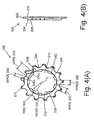
- Fig, 4(a) is a front view of a particular embodiment of a thirteen-tooth sprocket 300
- Fig. 4(b) is a partial cross-sectional view of sprocket 300
- sprocket 300 is adapted to be installed on either one of the first outer peripheral surface portion 90 or second outer peripheral surface portion 94 of sprocket support 74.
- Sprocket 300 comprises a sprocket body 304 having side surface 308 and 310 and an inner peripheral surface 312 defining a sprocket mounting opening 316, wherein at least one portion of the inner peripheral surface 312 is adapted to contact sprocket support 74.
- Sprocket 300 further comprises a plurality of sprocket teeth 320 extending radially outwardly from the sprocket body 304, wherein the lower portion of sprocket body 304 is axially offset from the plurality of sprocket teeth 320 (to the left in Fig. 4(b)).
- Inner peripheral surface 312 of sprocket 300 also defines at least one radially inwardly extending spline 336 and one radially outwardly extending spline 340.
- Each radially inwardly extending spline 336 has a radially inner surface 338, and each radially outwardly extending spline has a radially outer surface 342.
- each radially inwardly extending spline 336 alternates with a corresponding radially outwardly extending spline 340.
- the circumferential width WRIS300 of each of the plurality of radially inwardly extending splines 336 is the same except for a circumferential width WPIS300 of a radially inwardly extending positioning spline 336a.
- the circumferential width WROS300 of each of the plurality of radially outwardly extending splines 340 is the same except for a circumferential width WPOS300 of a radially outwardly extending positioning spline 340a.
- the distance RISD300 of the radially inner surface 338 of each of the plurality of radially inwardly extending splines 336 from the center C of sprocket 300 is the same, and the distance ROSD300 of the radially outer surface 342 of each of the plurality of radially outwardly extending splines 340 from the center C of sprocket 300 is the same. Furthermore, the distances RISD200 of sprocket 200 and RISD300 of sprocket 300 are the same.
- the radially inwardly extending splines 110 and 126 of first outer peripheral surface portion 90 and second outer peripheral surface portion 94 of sprocket support 74, respectively, can accommodate the radially inwardly extending splines 236 and 336 of both sprockets 200 and 300, respectively.
- sprocket 200 will not be mounted to the second outer peripheral surface portion 94 of sprocket support 74.
- the distance ROSD200 of the radially outer surface 242 of each of the plurality of radially outwardly extending splines 240 from the center C of sprocket 200 is the same, and the distance ROSD300 of the radially outer surface 342 of each of the plurality of radially outwardly extending splines 340 from the center C of the sprocket 300 is the same.
- the distance ROSD200 of the radially outer surface 242 of each of the plurality of radially outwardly extending splines 240 from the center C of sprocket 200 is substantially equal to the distance ROD1 of the radially outer surface 122 of each of the plurality of radially outwardly extending splines 114 from the center C of sprocket support 74, and that the distance ROSD300 of the radially outer surface 342 of each of the plurality of radially outwardly extending splines 340 from the center C of sprocket 300 is substantially equal to the distance ROD2 of the radially outer surface 138 of each of the plurality of radially outwardly extending splines 130 from the center C of sprocket support 74.
- sprocket 300 may be mounted on either the first outer peripheral surface portion 90 or the second outer peripheral surface portion 94 of sprocket support 74, which allows for interchangeability of sprockets and/or greater flexibility of sprocket positioning.
- RID1 RID2
- the sprocket support is made of steel or light alloy.
- the gap ROD1 - RID1 is rather small, but since the strength of the steel is strong, the mesh between the splines of the sprocket support and the splines of the sprocket remain adequate.
- the sprocket support is made of light alloy, then the gap is too narrow and the sprocket tends to shear off the splines on the sprocket support.
- the gap ROD1 - RID1 is made greater, and new sprockets are designed to match the new spline distances of the sprocket support.
- RID1 is made smaller than existing sprocket supports, then the new sprockets cannot be used with existing sprocket supports, and interchangeability is destroyed.
- ROD1 is made larger than existing sprocket supports, then the radial distances of the splines on the smaller sprockets must be increased accordingly, which lowers the strength of the smaller sprocket.
- the first outer peripheral surface portion 90 is made with the same distances as known sprocket supports. However, rather than increase the radial distance of the small sprocket splines, the lateral projections 224 are used to strengthen the sprocket as described below.
- Fig. 5 is a partial cross-sectional view of an embodiment of a plurality of sprockets mounted on the sprocket support 74.
- sprockets 404a and 404b having a varying number of teeth are mounted to the second outer peripheral surface portion 94 of sprocket support 74 through a sprocket adapter 420a
- sprockets 404c and 404d having a varying number of teeth are mounted to the second outer peripheral surface portion 94 of sprocket support 74 through a sprocket adapter 420b.
- Sprocket adapters 420a and 420b have radially inwardly extending splines and radially outwardly extending splines (including positioning splines, not shown) in the same manner as the radially inwardly extending splines 336, 336a and radially outwardly extending splines 340, 340a of sprocket 300.
- Another plurality of sprockets 404e, 404f and 404g having a varying number of teeth are directly mounted to the second outer peripheral surface portion 94 of sprocket support 74.
- the inner peripheral surface of sprockets 404e, 404f and 404g have radially inwardly extending splines and radially outwardly extending splines (including positioning splines, not shown) in the same manner as the radially inwardly extending splines 336, 336a and radially outwardly extending splines 340, 340a of sprocket 300.
- Sprockets 404e and 404f are axially separated from each other by a spacer 424a
- sprockets 404f and 404g are axially separated from each other by a spacer 424b.
- sprocket 300 is mounted on the second radially outer peripheral surface 94 of sprocket support 74, and the lower portion of sprocket body 304 of sprocket 300 abuts against the right side surface of sprocket 404g and functions as a spacer.
- Such a configuration also allows the radially inwardly extending splines 336 and 336a of sprocket 300 to have a greater axial thickness.
- the radially inwardly extending splines 336 of sprocket 300 completely engage the radially inwardly extending splines 126 of the second outer peripheral surface portion 94 of sprocket support 74 (i.e., the radially inner surfaces 338 of radially inwardly extending splines 336 almost or in fact contact the corresponding radially inner surfaces 134 of radially inwardly extending splines 126 of sprocket support 74). Furthermore, the radially inwardly extending positioning spline 336a of sprocket 300 completely engages the radially inwardly extending positioning spline 126a of sprocket support 74.
- the radially outwardly extending splines 340 of sprocket 300 completely engage the radially outwardly extending splines 130 of the second outer peripheral surface portion 94 of sprocket support 74, and the radially outwardly extending spline 340a of sprocket 300 completely engages the radially outwardly extending spline 130a of sprocket support 74.
- sprocket 200 is mounted on the first radially outer peripheral surface 90 of sprocket support 74.
- the radially inwardly extending splines 236, 236a of sprocket 200 completely engage the respective radially inwardly extending splines 110, 110a of the first outer peripheral surface portion 90 of sprocket support 74, and the radially outwardly extending splines 240, 240a of sprocket 200 completely engage the respective radially outwardly extending splines 114, 114a of the first outer peripheral surface portion 90 of sprocket support 74.
- the lower portion of sprocket body 204 abuts against transition surface 142.
- the radially inwardly extending splines 336 of sprocket 300 are laterally offset from the plurality of sprocket teeth 320, the radially outer surfaces 232 of lateral projections 224 of sprocket 200 may extend under and contact the inner peripheral surface 312 of sprocket 300. This provides further support and stabilization for sprocket 300.
- the shaded portion at sprocket 200 represents the engagement between the radially inwardly extending splines 110 of sprocket support 74 and the corresponding radially inwardly extending splines 236 of sprocket 200.
- the clear portion to the right of the shaded portion indicates the engagement between the radially outwardly extending splines 114 of sprocket support 74 and the corresponding radially outwardly extending splines 240 of sprocket 200.
- sprocket 200 can be mounted on first outer peripheral surface portion 90 of sprocket support 74 in a predetermined rotational direction. This is very helpful when the various sprockets mounted on sprocket support 74 must have a predetermined rotational position relative to each other, such as when there are chain shift facilitating structures on the various sprockets.
- Another sprocket 404h (e.g., an eleven tooth sprocket) is attached to the laterally outermost end of sprocket support 74 using a convenient means such as an annular nut (not shown) that screws onto the threaded portion 92 of sprocket support 74.
- Fig. 6 is a partial cross-sectional view of another embodiment of a plurality of sprockets mounted on the sprocket support 74.
- This embodiment is very similar to the embodiment shown in Fig. 5 in that it includes sprockets 404a-404g mounted to the second outer peripheral surface portion 94 of sprocket support 74.
- an extra sprocket 404i mounted to the second outer peripheral surface portion 94 of sprocket support 74, and both sprockets 200 and 300 are mounted on the first outer peripheral surface portion 90 of sprocket support 74.
- the distances RID1, RID2, RISD200 and RISD300 of the first outer peripheral surface 90 of sprocket support 74, the second outer peripheral surface 94 of sprocket support 74, sprocket 200 and sprocket 300, respectively, are the same, so the radially inwardly extending splines 110 of first outer peripheral surface portion 90 of sprocket support 74 can completely accommodate the radially inwardly extending splines 236 and 336 of both sprockets 200 and 300, respectively.
- the distance ROSD300 of sprocket 300 is greater than the distance ROSD200 of sprocket 200, and the distance ROD2 of the second outer peripheral surface 94 of sprocket support 74 is greater than the distance ROD1 of sprocket support 74.
- the radially outwardly extending splines 114 and 114a of the first outer peripheral surface portion 90 of sprocket support 74 can accommodate the radially outwardly extending splines 340 and 340a of sprocket 300, with a slight radial space between the radially outwardly extending splines 114 and 114a of sprocket support 74 and the radially outwardly extending splines 340 and 340a of sprocket 300.
- the added axial thickness of radially inwardly extending splines 340 help reinforce sprocket 300 in this position.
- Sprocket 200 may be mounted to the laterally outermost end of sprocket support 74 in the same manner as sprocket 404h in the embodiment shown in Fig. 5.
- Another sprocket or annular nut (not shown) may be screwed onto the threaded portion 92 of sprocket support 74 to axially fix the plurality of sprockets.
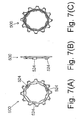
- Fig, 7(a) is a rear view of another embodiment of a twelve-tooth sprocket 500
- Fig. 7(b) is a partial cross-sectional view of sprocket 500
- Fig. 7(c) is a front view sprocket 500.
- Sprocket 500 is constructed the same as sprocket 200 shown in Figs. 3(a) - 3(c), except there are three evenly spaced lateral projections 524.
- Fig. 8 is a front view of another embodiment of a thirteen-tooth sprocket 600.
- Sprocket 600 may be used with sprocket 500 shown in Figs. 7(a) - 7(c), and it is adapted to be mounted on the first outer peripheral surface portion 90 of sprocket support 74.
- lateral projection receiving recesses 610 extend radially outwardly from radially outwardly extending splines 618 in locations where radially inwardly extending splines similar to radially inwardly extending splines 622 ordinarily would be located.
- Each lateral projection receiving recess 610 meshes with a corresponding lateral projection such as lateral projection 524 of sprocket 500 shown in Figs. 7(a) - 7(c).
- the lateral projections 524 of sprocket 500 support the inner peripheral surface 614 of sprocket 600 in those areas, thus increasing the ability of sprocket 600 to withstand stress.
- the distances RISD600 and ROSD600 are the same as distances RISD200 and ROSD200, respectively, of sprocket 200.
- Fig. 9 is a front view of another embodiment of a thirteen-tooth sprocket 700.
- Sprocket 700 also may be used with sprocket 500 shown in Figs. 7(a) - 7(c).
- sprocket 700 is adapted to he mounted on either the first outer peripheral surface 90 of sprocket support 74 or the second outer peripheral surface portion 94 of sprocket support 74.
- the distances RISD700 and ROSD700 of radially inwardly extending splines 730 and radially outwardly extending splines 734 of sprocket 700, respectively, from the center C of sprocket 700 are the same as the distances RISD300 and ROSD300 of the corresponding splines in sprocket 300.
- radially outwardly extending splines 734 circumferentially merge at three locations, 734x, 734y and 734z of inner peripheral surface 714, and there are no radially inwardly extending splines 730 in those locations.
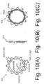
- Fig, 10(a) is a rear view of another embodiment of a twelve-tooth sprocket 800
- Fig. 10(b) is a partial cross-sectional side view of sprocket 800
- Fig. 10(c) is a front view sprocket 800
- Fig. 11 is a rear view of a thirteen-tooth sprocket 900 that may be used with twelve-tooth sprocket 800.
- Sprocket 800 is constructed the same as sprocket 500 shown in Figs.
- one of the three evenly spaced lateral projections 824a has a width WPLP800 that is different from the width WRLP800 of at least one of the other lateral projections 824b and 824c.
- the width WPLP800 of lateral projection 824a is different from the widths WRLP800 of both of the other two lateral projections 824b and 824c, which have the same widths. It should be noted that radially inwardly extending positioning splines 836a and radially outwardly extending positioning splines 840a are still retained.
- Sprocket 800 may be used with sprocket 900 shown in Fig. 11.
- Sprocket 900 is constructed the same as sprocket 600 shown in Fig. 8, except that at least one of the three evenly spaced lateral projection receiving recesses 910a, 910b and 910c has a width WPRR900 that is different from a width WRRR900 of at least one of the other lateral projection receiving recesses 910a, 910b and 910c.
- the width WPRR900 of lateral projection receiving recess 910a is different from the widths WRRR900 of both of the other two lateral projection receiving recesses 910b and 910c, which have the same widths.
- the distances RISD800 and ROSD800 of sprocket 800 are the same as the distances RISD600 and ROSD600 of sprocket 600, respectively, so sprocket 800 is adapted to be mounted to the first outer peripheral surface portion 90 of sprocket support 74.
- Lateral projection 824a of sprocket 800 may mesh with lateral projection receiving recess 910a of sprocket 900, and the lateral projections 824b and 824c of sprocket 800 may mesh with lateral projection receiving recesses 910b and 910c of sprocket 900. This promotes a good coupling between sprockets 800 and 900, but at a predetermined position relative to each other.
- radially inwardly extending positioning splines 836a, 840a and radially outwardly extending positioning splines 936a and 940a are still retained.
- inventive features should not be limited to the twelve- and thirteen-tooth sprockets described. While a plurality of lateral projections, radially inwardly extending splines and radially outwardly extending splines were disclosed, in some embodiments only one of any of the foregoing may be desirable. While a plurality of distinct lateral projections were disclosed, in other embodiments there may be a configuration where different radial widths or some other characteristic of a single lateral projection, for example, is desirable.
Landscapes
- Engineering & Computer Science (AREA)
- Mechanical Engineering (AREA)
- Chemical & Material Sciences (AREA)
- Combustion & Propulsion (AREA)
- Transportation (AREA)
- Gears, Cams (AREA)
- Transmissions By Endless Flexible Members (AREA)
Applications Claiming Priority (2)
| Application Number | Priority Date | Filing Date | Title |
|---|---|---|---|
| US10/346,819 US7044876B2 (en) | 2003-01-17 | 2003-01-17 | Bicycle sprocket having lateral protrusions for use in a multiple sprocket assembly |
| US346819 | 2003-01-17 |
Publications (3)
| Publication Number | Publication Date |
|---|---|
| EP1439118A2 true EP1439118A2 (fr) | 2004-07-21 |
| EP1439118A3 EP1439118A3 (fr) | 2005-04-06 |
| EP1439118B1 EP1439118B1 (fr) | 2007-07-11 |
Family
ID=32594890
Family Applications (1)
| Application Number | Title | Priority Date | Filing Date |
|---|---|---|---|
| EP04000778A Expired - Lifetime EP1439118B1 (fr) | 2003-01-17 | 2004-01-15 | Pignon de bicyclette ayant des protubérances latérales à utiliser dans un ensemble de pignons |
Country Status (7)
| Country | Link |
|---|---|
| US (1) | US7044876B2 (fr) |
| EP (1) | EP1439118B1 (fr) |
| JP (1) | JP2004224334A (fr) |
| CN (1) | CN1265997C (fr) |
| AT (1) | ATE366692T1 (fr) |
| DE (1) | DE602004007414T2 (fr) |
| TW (1) | TWI272213B (fr) |
Cited By (4)
| Publication number | Priority date | Publication date | Assignee | Title |
|---|---|---|---|---|
| EP2048075A3 (fr) * | 2007-10-11 | 2010-11-17 | Shimano Inc. | Ensemble pignon arrière de bicyclette |
| US11351815B2 (en) | 2017-08-21 | 2022-06-07 | The Hive Global, Inc. | Bicycle cassette with clamping connection |
| US11485449B2 (en) | 2015-09-01 | 2022-11-01 | The Hive Global, Inc. | Bicycle cassette with locking connection |
| US11932351B2 (en) | 2020-07-17 | 2024-03-19 | The Hive Global, Inc. | Conical bicycle cassette sprocket structure |
Families Citing this family (34)
| Publication number | Priority date | Publication date | Assignee | Title |
|---|---|---|---|---|
| US6866604B2 (en) * | 2003-01-17 | 2005-03-15 | Shimano, Inc. | Multiple level sprocket support for a bicycle |
| JP2005238873A (ja) * | 2004-02-24 | 2005-09-08 | Shimano Inc | 自転車用変速制御装置及びフロントディレーラの制御方法 |
| US7846047B2 (en) * | 2004-09-10 | 2010-12-07 | Shimano, Inc. | Bicycle sprocket having a thickened spline |
| US20080004143A1 (en) * | 2006-06-16 | 2008-01-03 | Shimano Inc. | Bicycle sprocket assembly |
| JP2008189254A (ja) * | 2007-02-07 | 2008-08-21 | Shimano Inc | 自転車用リアスプロケット組立体及びスプロケット |
| US20100099530A1 (en) * | 2008-03-28 | 2010-04-22 | Douglas Chiang | Bicycle Cogset |
| US20090243250A1 (en) * | 2008-03-28 | 2009-10-01 | Tien Hsin Industries Co., Ltd. | Bicycle sprocket assembly |
| US20100009794A1 (en) * | 2008-07-10 | 2010-01-14 | Douglas Chiang | Sprocket assembly |
| US9193416B2 (en) * | 2009-11-30 | 2015-11-24 | Shimano Inc. | Bicycle sprocket support assembly |
| US8641151B2 (en) | 2010-11-12 | 2014-02-04 | Shimano Inc. | Sprocket support structure |
| TWI701186B (zh) | 2011-07-13 | 2020-08-11 | 德商矢倫德國股份有限公司 | 支載腳踏車變速器所用之備有小鏈輪的多鏈輪配置的傳動座體裝置 |
| CN203111435U (zh) * | 2013-01-30 | 2013-08-07 | 大行科技(深圳)有限公司 | 自行车链轮组件 |
| CN203111436U (zh) * | 2013-01-30 | 2013-08-07 | 大行科技(深圳)有限公司 | 自行车链轮组件 |
| US9649880B2 (en) * | 2015-01-29 | 2017-05-16 | Shimano Inc. | Bicycle hub assembly |
| DE102015203709A1 (de) * | 2015-03-02 | 2016-09-08 | Sram Deutschland Gmbh | Ritzelanordnung mit Adapter |
| US10093388B2 (en) * | 2016-06-28 | 2018-10-09 | Shimano Inc. | Bicycle rear sprocket assembly |
| US10053187B2 (en) * | 2016-07-07 | 2018-08-21 | Shimano Inc. | Bicycle rear sprocket assembly and bicycle rear sprocket |
| US9868491B1 (en) * | 2016-07-21 | 2018-01-16 | Shimano Inc. | Bicycle sprocket assembly |
| US11059541B2 (en) * | 2017-05-30 | 2021-07-13 | Shimano Inc. | Bicycle hub assembly |
| US11179967B2 (en) | 2017-05-30 | 2021-11-23 | Shimano Inc. | Bicycle hub assembly |
| US11220309B2 (en) * | 2017-05-30 | 2022-01-11 | Shimano Inc. | Bicycle rear sprocket assembly |
| US10377174B2 (en) | 2017-08-09 | 2019-08-13 | Shimano Inc. | Bicycle hub assembly |
| US11332213B2 (en) * | 2017-05-30 | 2022-05-17 | Shimano Inc. | Bicycle rear sprocket assembly and bicycle drive train |
| US10752320B2 (en) | 2017-09-22 | 2020-08-25 | Shimano Inc. | Bicycle rear hub assembly |
| CN113581359B (zh) * | 2017-05-30 | 2022-09-02 | 株式会社岛野 | 自行车后链轮组件和用于其的链轮支撑构件 |
| CN111469972B (zh) * | 2017-05-30 | 2023-02-17 | 株式会社岛野 | 自行车后链轮组件 |
| CN108973523B (zh) * | 2017-05-30 | 2021-10-15 | 株式会社岛野 | 自行车花鼓组件 |
| US10946931B2 (en) * | 2017-09-22 | 2021-03-16 | Shimano Inc. | Bicycle rear sprocket assembly and bicycle drive train |
| DE102019107111A1 (de) * | 2019-03-20 | 2020-09-24 | Shimano Inc. | Kettenradstützkörper; fahrradnabenanordnung und antriebsstrang |
| US11578761B2 (en) * | 2019-03-22 | 2023-02-14 | Shimano Inc. | Bicycle sprocket arrangement |
| IT201900013287A1 (it) * | 2019-07-30 | 2021-01-30 | Campagnolo Srl | Adattatore per un corpo porta-pignoni per una ruota posteriore di bicicletta |
| US11591043B2 (en) | 2019-07-30 | 2023-02-28 | Campagnolo S.R.L. | Sprocket-carrying body and sub-assembly of sprocket-carrying body and cogset for a bicycle rear wheel |
| TWI759006B (zh) * | 2020-12-11 | 2022-03-21 | 彥豪金屬工業股份有限公司 | 自行車後飛輪 |
| US20240067299A1 (en) * | 2022-08-30 | 2024-02-29 | Shimano Inc. | Rear sprocket |
Citations (11)
| Publication number | Priority date | Publication date | Assignee | Title |
|---|---|---|---|---|
| GB662068A (en) * | 1949-03-12 | 1951-11-28 | Edwin Fernand Camillis | Improved multiple chain wheel assembly for cycle hub |
| FR2157287A5 (fr) * | 1971-10-23 | 1973-06-01 | Zeus Industrial | |
| US3900088A (en) * | 1972-01-27 | 1975-08-19 | Maeda Ind | Bicycle free wheel assembly |
| US4486184A (en) * | 1981-09-22 | 1984-12-04 | Campagnolo S.P.A. | Free-wheel for bicycles |
| FR2588236A3 (fr) * | 1985-10-07 | 1987-04-10 | Marchisio Dante | Dispositif de roue libre pour bicyclettes ou similaires |
| US4674617A (en) * | 1983-04-25 | 1987-06-23 | Shimano Industrial Company Limited | Freewheel for a bicycle |
| DE3810974A1 (de) * | 1987-03-27 | 1988-12-01 | Lothar Blankenburg | Zahnkettenradsatz fuer kettenschaltungen fuer fahrraeder |
| FR2622842A1 (fr) * | 1987-11-06 | 1989-05-12 | Teyssier Yves | Moyeu arriere de cycle combine avec la roue libre |
| EP0689988A1 (fr) * | 1994-06-29 | 1996-01-03 | FICHTEL & SACHS AG | Dérailleur, notamment pour bicyclettes |
| US5522611A (en) * | 1994-01-18 | 1996-06-04 | Fichtel & Sachs Ag | Multiple sprocket chainwheel for bicycle derailleur |
| US20010039224A1 (en) * | 1999-04-08 | 2001-11-08 | Lim Puat Thiam | Freewheel for a bicycle |
Family Cites Families (11)
| Publication number | Priority date | Publication date | Assignee | Title |
|---|---|---|---|---|
| US3707884A (en) * | 1970-11-20 | 1973-01-02 | J Go | Method and device for power transmission transfer |
| US4121474A (en) * | 1971-10-23 | 1978-10-24 | Jose Domingo Arregui Suinaga | Multiple crown free wheel systems for bicycles |
| IT7822169V0 (it) * | 1978-06-23 | 1978-06-23 | Campagnolo Tullio | Dispositivo di ruota libera per biciclette. |
| JP3033633B2 (ja) * | 1992-03-23 | 2000-04-17 | 古河電気工業株式会社 | 撚線機 |
| JP3507096B2 (ja) * | 1993-04-20 | 2004-03-15 | 株式会社大正製作所 | 変速式自転車の後輪側被駆動トップ用スプロケット |
| US5860882A (en) * | 1996-01-31 | 1999-01-19 | Borg-Warner Automotive, Inc. | Process for manufacturing phased sprocket assemblies by capacitor discharge welding |
| IT1286121B1 (it) * | 1996-06-25 | 1998-07-07 | Campagnolo Srl | Pignone, per l'ingranamento con una catena di bicicletta. |
| IT1289715B1 (it) * | 1996-12-05 | 1998-10-16 | Campagnolo Srl | Gruppo sopporto pignoni per una bicicletta |
| EP0988218A1 (fr) * | 1997-06-09 | 2000-03-29 | World Industry Co., Ltd. | Dispositif destine a changer le sens de rotation de l'axe de pedalier d'une bicyclette |
| US5733215A (en) * | 1997-06-23 | 1998-03-31 | Industrial Technology Research Institute | Multi-speed sprocket assembly of a bicycle |
| IT1320644B1 (it) | 2000-09-15 | 2003-12-10 | Campagnolo Srl | Mozzo ruota per bicicletta. |
-
2003
- 2003-01-17 US US10/346,819 patent/US7044876B2/en not_active Expired - Lifetime
- 2003-12-03 TW TW092134060A patent/TWI272213B/zh not_active IP Right Cessation
-
2004
- 2004-01-15 AT AT04000778T patent/ATE366692T1/de not_active IP Right Cessation
- 2004-01-15 JP JP2004007915A patent/JP2004224334A/ja not_active Withdrawn
- 2004-01-15 DE DE602004007414T patent/DE602004007414T2/de not_active Expired - Lifetime
- 2004-01-15 EP EP04000778A patent/EP1439118B1/fr not_active Expired - Lifetime
- 2004-01-16 CN CNB2004100019790A patent/CN1265997C/zh not_active Expired - Fee Related
Patent Citations (11)
| Publication number | Priority date | Publication date | Assignee | Title |
|---|---|---|---|---|
| GB662068A (en) * | 1949-03-12 | 1951-11-28 | Edwin Fernand Camillis | Improved multiple chain wheel assembly for cycle hub |
| FR2157287A5 (fr) * | 1971-10-23 | 1973-06-01 | Zeus Industrial | |
| US3900088A (en) * | 1972-01-27 | 1975-08-19 | Maeda Ind | Bicycle free wheel assembly |
| US4486184A (en) * | 1981-09-22 | 1984-12-04 | Campagnolo S.P.A. | Free-wheel for bicycles |
| US4674617A (en) * | 1983-04-25 | 1987-06-23 | Shimano Industrial Company Limited | Freewheel for a bicycle |
| FR2588236A3 (fr) * | 1985-10-07 | 1987-04-10 | Marchisio Dante | Dispositif de roue libre pour bicyclettes ou similaires |
| DE3810974A1 (de) * | 1987-03-27 | 1988-12-01 | Lothar Blankenburg | Zahnkettenradsatz fuer kettenschaltungen fuer fahrraeder |
| FR2622842A1 (fr) * | 1987-11-06 | 1989-05-12 | Teyssier Yves | Moyeu arriere de cycle combine avec la roue libre |
| US5522611A (en) * | 1994-01-18 | 1996-06-04 | Fichtel & Sachs Ag | Multiple sprocket chainwheel for bicycle derailleur |
| EP0689988A1 (fr) * | 1994-06-29 | 1996-01-03 | FICHTEL & SACHS AG | Dérailleur, notamment pour bicyclettes |
| US20010039224A1 (en) * | 1999-04-08 | 2001-11-08 | Lim Puat Thiam | Freewheel for a bicycle |
Cited By (5)
| Publication number | Priority date | Publication date | Assignee | Title |
|---|---|---|---|---|
| EP2048075A3 (fr) * | 2007-10-11 | 2010-11-17 | Shimano Inc. | Ensemble pignon arrière de bicyclette |
| US7871347B2 (en) | 2007-10-11 | 2011-01-18 | Shimano Inc. | Bicycle rear sprocket assembly |
| US11485449B2 (en) | 2015-09-01 | 2022-11-01 | The Hive Global, Inc. | Bicycle cassette with locking connection |
| US11351815B2 (en) | 2017-08-21 | 2022-06-07 | The Hive Global, Inc. | Bicycle cassette with clamping connection |
| US11932351B2 (en) | 2020-07-17 | 2024-03-19 | The Hive Global, Inc. | Conical bicycle cassette sprocket structure |
Also Published As
| Publication number | Publication date |
|---|---|
| DE602004007414T2 (de) | 2008-08-14 |
| US20040142783A1 (en) | 2004-07-22 |
| JP2004224334A (ja) | 2004-08-12 |
| EP1439118A3 (fr) | 2005-04-06 |
| DE602004007414D1 (de) | 2007-08-23 |
| CN1517267A (zh) | 2004-08-04 |
| ATE366692T1 (de) | 2007-08-15 |
| CN1265997C (zh) | 2006-07-26 |
| EP1439118B1 (fr) | 2007-07-11 |
| US7044876B2 (en) | 2006-05-16 |
| TW200415071A (en) | 2004-08-16 |
| TWI272213B (en) | 2007-02-01 |
Similar Documents
| Publication | Publication Date | Title |
|---|---|---|
| EP1439118B1 (fr) | Pignon de bicyclette ayant des protubérances latérales à utiliser dans un ensemble de pignons | |
| EP1439117B1 (fr) | Pignon multiple pour des dérailleurs de bicyclette | |
| EP1634806B1 (fr) | Pinion de bicyclette avec nervure épaissie | |
| EP2452865B1 (fr) | Structure de support de pignon | |
| US8956254B2 (en) | Bicycle sprocket assembly | |
| EP2495161B1 (fr) | Ensemble de pignon de bicyclette | |
| US7931553B2 (en) | Bicycle sprocket apparatus with a chain support structure | |
| US6497314B2 (en) | Bicycle hub with sliding engagement member and detachable freewheel | |
| US20120196711A1 (en) | Bicycle sprocket assembly | |
| EP1995166B1 (fr) | Ensemble de pignons avec protecteur de chaîne | |
| EP0834450B2 (fr) | Ensemble de jeu de pignons à chaîne pour bicyclette pour fixer un pignon sur la bague extérieure | |
| EP1043221A2 (fr) | Roue libre pour une bicyclette | |
| EP1652767A2 (fr) | Pédalier pour bicyclette | |
| US10625814B2 (en) | Bicycle crank assembly |
Legal Events
| Date | Code | Title | Description |
|---|---|---|---|
| PUAI | Public reference made under article 153(3) epc to a published international application that has entered the european phase |
Free format text: ORIGINAL CODE: 0009012 |
|
| AK | Designated contracting states |
Kind code of ref document: A2 Designated state(s): AT BE BG CH CY CZ DE DK EE ES FI FR GB GR HU IE IT LI LU MC NL PT RO SE SI SK TR |
|
| AX | Request for extension of the european patent |
Extension state: AL LT LV MK |
|
| PUAL | Search report despatched |
Free format text: ORIGINAL CODE: 0009013 |
|
| AK | Designated contracting states |
Kind code of ref document: A3 Designated state(s): AT BE BG CH CY CZ DE DK EE ES FI FR GB GR HU IE IT LI LU MC NL PT RO SE SI SK TR |
|
| AX | Request for extension of the european patent |
Extension state: AL LT LV MK |
|
| RIC1 | Information provided on ipc code assigned before grant |
Ipc: 7B 62M 9/10 A Ipc: 7F 16H 55/30 B |
|
| 17P | Request for examination filed |
Effective date: 20050330 |
|
| 17Q | First examination report despatched |
Effective date: 20050531 |
|
| AKX | Designation fees paid |
Designated state(s): AT BE BG CH CY CZ DE DK EE ES FI FR GB GR HU IE IT LI LU MC NL PT RO SE SI SK TR |
|
| RAP1 | Party data changed (applicant data changed or rights of an application transferred) |
Owner name: SHIMANO INC. |
|
| GRAP | Despatch of communication of intention to grant a patent |
Free format text: ORIGINAL CODE: EPIDOSNIGR1 |
|
| GRAS | Grant fee paid |
Free format text: ORIGINAL CODE: EPIDOSNIGR3 |
|
| GRAA | (expected) grant |
Free format text: ORIGINAL CODE: 0009210 |
|
| AK | Designated contracting states |
Kind code of ref document: B1 Designated state(s): AT BE BG CH CY CZ DE DK EE ES FI FR GB GR HU IE IT LI LU MC NL PT RO SE SI SK TR |
|
| REG | Reference to a national code |
Ref country code: GB Ref legal event code: FG4D |
|
| REG | Reference to a national code |
Ref country code: CH Ref legal event code: EP |
|
| REF | Corresponds to: |
Ref document number: 602004007414 Country of ref document: DE Date of ref document: 20070823 Kind code of ref document: P |
|
| REG | Reference to a national code |
Ref country code: IE Ref legal event code: FG4D |
|
| ET | Fr: translation filed | ||
| PG25 | Lapsed in a contracting state [announced via postgrant information from national office to epo] |
Ref country code: ES Free format text: LAPSE BECAUSE OF FAILURE TO SUBMIT A TRANSLATION OF THE DESCRIPTION OR TO PAY THE FEE WITHIN THE PRESCRIBED TIME-LIMIT Effective date: 20071022 Ref country code: PT Free format text: LAPSE BECAUSE OF FAILURE TO SUBMIT A TRANSLATION OF THE DESCRIPTION OR TO PAY THE FEE WITHIN THE PRESCRIBED TIME-LIMIT Effective date: 20071211 Ref country code: BG Free format text: LAPSE BECAUSE OF FAILURE TO SUBMIT A TRANSLATION OF THE DESCRIPTION OR TO PAY THE FEE WITHIN THE PRESCRIBED TIME-LIMIT Effective date: 20071011 Ref country code: FI Free format text: LAPSE BECAUSE OF FAILURE TO SUBMIT A TRANSLATION OF THE DESCRIPTION OR TO PAY THE FEE WITHIN THE PRESCRIBED TIME-LIMIT Effective date: 20070711 |
|
| REG | Reference to a national code |
Ref country code: CH Ref legal event code: PL |
|
| PG25 | Lapsed in a contracting state [announced via postgrant information from national office to epo] |
Ref country code: AT Free format text: LAPSE BECAUSE OF FAILURE TO SUBMIT A TRANSLATION OF THE DESCRIPTION OR TO PAY THE FEE WITHIN THE PRESCRIBED TIME-LIMIT Effective date: 20070711 Ref country code: LI Free format text: LAPSE BECAUSE OF FAILURE TO SUBMIT A TRANSLATION OF THE DESCRIPTION OR TO PAY THE FEE WITHIN THE PRESCRIBED TIME-LIMIT Effective date: 20070711 Ref country code: CH Free format text: LAPSE BECAUSE OF FAILURE TO SUBMIT A TRANSLATION OF THE DESCRIPTION OR TO PAY THE FEE WITHIN THE PRESCRIBED TIME-LIMIT Effective date: 20070711 |
|
| PG25 | Lapsed in a contracting state [announced via postgrant information from national office to epo] |
Ref country code: BE Free format text: LAPSE BECAUSE OF FAILURE TO SUBMIT A TRANSLATION OF THE DESCRIPTION OR TO PAY THE FEE WITHIN THE PRESCRIBED TIME-LIMIT Effective date: 20070711 |
|
| PG25 | Lapsed in a contracting state [announced via postgrant information from national office to epo] |
Ref country code: GR Free format text: LAPSE BECAUSE OF FAILURE TO SUBMIT A TRANSLATION OF THE DESCRIPTION OR TO PAY THE FEE WITHIN THE PRESCRIBED TIME-LIMIT Effective date: 20071012 Ref country code: DK Free format text: LAPSE BECAUSE OF FAILURE TO SUBMIT A TRANSLATION OF THE DESCRIPTION OR TO PAY THE FEE WITHIN THE PRESCRIBED TIME-LIMIT Effective date: 20070711 |
|
| PLBE | No opposition filed within time limit |
Free format text: ORIGINAL CODE: 0009261 |
|
| STAA | Information on the status of an ep patent application or granted ep patent |
Free format text: STATUS: NO OPPOSITION FILED WITHIN TIME LIMIT |
|
| PG25 | Lapsed in a contracting state [announced via postgrant information from national office to epo] |
Ref country code: CZ Free format text: LAPSE BECAUSE OF FAILURE TO SUBMIT A TRANSLATION OF THE DESCRIPTION OR TO PAY THE FEE WITHIN THE PRESCRIBED TIME-LIMIT Effective date: 20070711 Ref country code: SK Free format text: LAPSE BECAUSE OF FAILURE TO SUBMIT A TRANSLATION OF THE DESCRIPTION OR TO PAY THE FEE WITHIN THE PRESCRIBED TIME-LIMIT Effective date: 20070711 |
|
| PGFP | Annual fee paid to national office [announced via postgrant information from national office to epo] |
Ref country code: NL Payment date: 20080124 Year of fee payment: 5 |
|
| 26N | No opposition filed |
Effective date: 20080414 |
|
| PG25 | Lapsed in a contracting state [announced via postgrant information from national office to epo] |
Ref country code: SE Free format text: LAPSE BECAUSE OF FAILURE TO SUBMIT A TRANSLATION OF THE DESCRIPTION OR TO PAY THE FEE WITHIN THE PRESCRIBED TIME-LIMIT Effective date: 20071011 Ref country code: RO Free format text: LAPSE BECAUSE OF FAILURE TO SUBMIT A TRANSLATION OF THE DESCRIPTION OR TO PAY THE FEE WITHIN THE PRESCRIBED TIME-LIMIT Effective date: 20070711 |
|
| PG25 | Lapsed in a contracting state [announced via postgrant information from national office to epo] |
Ref country code: MC Free format text: LAPSE BECAUSE OF NON-PAYMENT OF DUE FEES Effective date: 20080131 |
|
| GBPC | Gb: european patent ceased through non-payment of renewal fee |
Effective date: 20080115 |
|
| PG25 | Lapsed in a contracting state [announced via postgrant information from national office to epo] |
Ref country code: GB Free format text: LAPSE BECAUSE OF NON-PAYMENT OF DUE FEES Effective date: 20080115 |
|
| PG25 | Lapsed in a contracting state [announced via postgrant information from national office to epo] |
Ref country code: IE Free format text: LAPSE BECAUSE OF NON-PAYMENT OF DUE FEES Effective date: 20080115 Ref country code: EE Free format text: LAPSE BECAUSE OF FAILURE TO SUBMIT A TRANSLATION OF THE DESCRIPTION OR TO PAY THE FEE WITHIN THE PRESCRIBED TIME-LIMIT Effective date: 20070711 |
|
| PG25 | Lapsed in a contracting state [announced via postgrant information from national office to epo] |
Ref country code: SI Free format text: LAPSE BECAUSE OF FAILURE TO SUBMIT A TRANSLATION OF THE DESCRIPTION OR TO PAY THE FEE WITHIN THE PRESCRIBED TIME-LIMIT Effective date: 20070711 |
|
| PG25 | Lapsed in a contracting state [announced via postgrant information from national office to epo] |
Ref country code: CY Free format text: LAPSE BECAUSE OF FAILURE TO SUBMIT A TRANSLATION OF THE DESCRIPTION OR TO PAY THE FEE WITHIN THE PRESCRIBED TIME-LIMIT Effective date: 20070711 |
|
| NLV4 | Nl: lapsed or anulled due to non-payment of the annual fee |
Effective date: 20090801 |
|
| PG25 | Lapsed in a contracting state [announced via postgrant information from national office to epo] |
Ref country code: NL Free format text: LAPSE BECAUSE OF NON-PAYMENT OF DUE FEES Effective date: 20090801 |
|
| PG25 | Lapsed in a contracting state [announced via postgrant information from national office to epo] |
Ref country code: LU Free format text: LAPSE BECAUSE OF NON-PAYMENT OF DUE FEES Effective date: 20080115 Ref country code: HU Free format text: LAPSE BECAUSE OF FAILURE TO SUBMIT A TRANSLATION OF THE DESCRIPTION OR TO PAY THE FEE WITHIN THE PRESCRIBED TIME-LIMIT Effective date: 20080112 |
|
| PG25 | Lapsed in a contracting state [announced via postgrant information from national office to epo] |
Ref country code: TR Free format text: LAPSE BECAUSE OF FAILURE TO SUBMIT A TRANSLATION OF THE DESCRIPTION OR TO PAY THE FEE WITHIN THE PRESCRIBED TIME-LIMIT Effective date: 20070711 |
|
| REG | Reference to a national code |
Ref country code: FR Ref legal event code: PLFP Year of fee payment: 13 |
|
| PGFP | Annual fee paid to national office [announced via postgrant information from national office to epo] |
Ref country code: FR Payment date: 20151208 Year of fee payment: 13 |
|
| PGFP | Annual fee paid to national office [announced via postgrant information from national office to epo] |
Ref country code: IT Payment date: 20160127 Year of fee payment: 13 |
|
| REG | Reference to a national code |
Ref country code: FR Ref legal event code: ST Effective date: 20170929 |
|
| PG25 | Lapsed in a contracting state [announced via postgrant information from national office to epo] |
Ref country code: FR Free format text: LAPSE BECAUSE OF NON-PAYMENT OF DUE FEES Effective date: 20170131 |
|
| PG25 | Lapsed in a contracting state [announced via postgrant information from national office to epo] |
Ref country code: IT Free format text: LAPSE BECAUSE OF NON-PAYMENT OF DUE FEES Effective date: 20170115 |
|
| PGFP | Annual fee paid to national office [announced via postgrant information from national office to epo] |
Ref country code: DE Payment date: 20210105 Year of fee payment: 18 |
|
| REG | Reference to a national code |
Ref country code: DE Ref legal event code: R119 Ref document number: 602004007414 Country of ref document: DE |
|
| PG25 | Lapsed in a contracting state [announced via postgrant information from national office to epo] |
Ref country code: DE Free format text: LAPSE BECAUSE OF NON-PAYMENT OF DUE FEES Effective date: 20220802 |