EP1439044A1 - Holzbearbeitungsmaschine mit Anschlagsystem - Google Patents
Holzbearbeitungsmaschine mit Anschlagsystem Download PDFInfo
- Publication number
- EP1439044A1 EP1439044A1 EP04000838A EP04000838A EP1439044A1 EP 1439044 A1 EP1439044 A1 EP 1439044A1 EP 04000838 A EP04000838 A EP 04000838A EP 04000838 A EP04000838 A EP 04000838A EP 1439044 A1 EP1439044 A1 EP 1439044A1
- Authority
- EP
- European Patent Office
- Prior art keywords
- base body
- stop
- stops
- machine according
- woodworking machine
- Prior art date
- Legal status (The legal status is an assumption and is not a legal conclusion. Google has not performed a legal analysis and makes no representation as to the accuracy of the status listed.)
- Granted
Links
- 239000002023 wood Substances 0.000 title description 2
- 230000000284 resting effect Effects 0.000 claims abstract 3
- 238000003754 machining Methods 0.000 claims description 18
- 230000007246 mechanism Effects 0.000 claims description 7
- 230000008878 coupling Effects 0.000 claims description 3
- 238000010168 coupling process Methods 0.000 claims description 3
- 238000005859 coupling reaction Methods 0.000 claims description 3
- 238000007688 edging Methods 0.000 description 8
- 238000005520 cutting process Methods 0.000 description 5
- 230000008859 change Effects 0.000 description 3
- 238000000034 method Methods 0.000 description 3
- 230000008569 process Effects 0.000 description 3
- 230000008901 benefit Effects 0.000 description 2
- 230000002349 favourable effect Effects 0.000 description 2
- 238000009966 trimming Methods 0.000 description 2
- 230000009471 action Effects 0.000 description 1
- 230000009286 beneficial effect Effects 0.000 description 1
- 230000015572 biosynthetic process Effects 0.000 description 1
- 238000010276 construction Methods 0.000 description 1
- 230000001419 dependent effect Effects 0.000 description 1
- 238000005516 engineering process Methods 0.000 description 1
- 125000006850 spacer group Chemical group 0.000 description 1
Images

Classifications
-
- B—PERFORMING OPERATIONS; TRANSPORTING
- B27—WORKING OR PRESERVING WOOD OR SIMILAR MATERIAL; NAILING OR STAPLING MACHINES IN GENERAL
- B27B—SAWS FOR WOOD OR SIMILAR MATERIAL; COMPONENTS OR ACCESSORIES THEREFOR
- B27B27/00—Guide fences or stops for timber in saw mills or sawing machines; Measuring equipment thereon
- B27B27/10—Devices for moving or adjusting the guide fences or stops
-
- B—PERFORMING OPERATIONS; TRANSPORTING
- B27—WORKING OR PRESERVING WOOD OR SIMILAR MATERIAL; NAILING OR STAPLING MACHINES IN GENERAL
- B27B—SAWS FOR WOOD OR SIMILAR MATERIAL; COMPONENTS OR ACCESSORIES THEREFOR
- B27B27/00—Guide fences or stops for timber in saw mills or sawing machines; Measuring equipment thereon
- B27B27/04—Guide fences or stops for timber in saw mills or sawing machines; Measuring equipment thereon arranged perpendicularly to the plane of the saw blade
Definitions
- the invention relates to a woodworking machine, in particular Format saw with a stop system, the a machining tool to be machined on the Support surface of a support table rests with several stops to guide the workpiece, at least one Stop is movable away from the support surface.
- Stop systems for processing machines are known. there the workpiece to be machined is placed on the support surface Support table laid on and guided at a stop. The The stop is made before machining the workpiece desired width and then the workpiece on this Stop for processing led.
- Such a stop system is for example from the Document DE 36 37 713 C2 known.
- the positioning stops are in Machining direction or conveying direction arranged one behind the other and have the same distance from each other.
- the configuration shown here is structurally very complex and therefore expensive.
- this proposal is also in the Operation very cumbersome because the individual stops to operate or to control. A short term and rapid change of the stops, for example due to a Format change is not possible with this proposal.
- a sliding table saw is also known, for example.
- Sliding table saws have a sliding table, which runs past a saw blade.
- At the edging table is in the Usually a cross table is attached.
- the workpiece lies on it the edging table and, if appropriate dimensions, also on the Cross table on.
- the stop or the stops are then at the cross table and usually reach up on the edging table.
- the object of the invention is achieved in that at least two stops together on a base body of the stop system are arranged and the stops by movement of the base body are movable in or out of the support surface. Through the joint movement of the stops through the movement operability of the base body is considerably facilitated. The position of the base body is used to activate or Deactivate the at different positions if necessary arranged stops. This solution is also constructive easy to implement, which results in good ergonomics and Ease of use to implement the proposal according to the invention connects.
- the Attacks not only by the body with respect to the Support surface can be moved back.
- they are all other movements conceivable that cause the stop of to move the support surface away, i.e. to position it in such a way that the stop no longer interact with the workpiece can.
- This solution becomes a woodworking machine according to the invention with an accurate and flexible stop system provided on the support table side, which for universal execution of cuts, in particular exact parallelism of the edges to be cut against the edge adjacent to the stops promoted becomes.
- at least one stop under the support surface can be lowered with the frequently occurring, different Widths at least the one with the smallest distance to the processing tool then stop under the contact surface be lowered when machining a wider workpiece must become.
- the contact surface to Example when loading with workpieces, such as large ones Wood panels can be cleared very quickly by simply all stops below the contact surface are lowered without that the attacks or those carrying the attacks Parts have to be disassembled.
- the stop system has a plurality of stops and, for example, only one stop, if this is namely is not needed, is lowered and another stop still in use, so a stop for that Workpiece forms.
- each on a support beam lowerable stops are used, which, depending on requirements, can be moved upwards over the contact surface if this are needed.
- the stops of the base body with different Distance to the processing tool and in different Locations, especially elevations or angles on Base body are arranged.
- the base body can be moved at right angles to the contact surface and the stops of different lengths, so that heights own and by the position of the body of the respective Stop is turned on or off.
- the same is in principle also possible with a rotatable body, in which the Stops in different angular positions of the rotatable body optionally also with the same or different lengths are arranged.
- the attacks are arranged at different distances from the processing tool, to easily change the format in the otherwise identical construction woodworking machine according to the invention to realize.
- the base body is rotatable or longitudinally movable, in particular at right angles to Support surface can be raised or lowered. All of these different Variants serve the basic body with the on it arranged stops to move away from the support surface or vice versa, the stops analogously in the contact surface to position. According to the invention is also provided that, for example, the stops project upwards, but each have a different effective length.
- Stop system is provided that the stop system is so low that each for processing suitable stop is positioned in the contact surface.
- System can be at least two, but in total also realize significantly more stops on the contact surface the support table are arranged, and then in are arranged at different heights, each of which The altitude is to be controlled, the stop width of the respective Stop is just needed.
- the base body allows a simple positioning of all stops to size.
- the various stops are at fixed intervals arranged from each other on the base body. A move of the base body thus positions the selected one Stop simple and easy to use.
- the same basic body serves with the same adjustment device for the dimensionally accurate Set all other stops if selected are.
- the lowering or raising of the stops with respect to the contact surface takes place according to an advantageous embodiment parallel or perpendicular to the support surface of the support table. This ensures that always an exact Position the workpieces on the system edges can, which increases or ensures overall dimensional accuracy becomes.
- Solutions known from the prior art are either not lowered to another level at all or but only by swiveling one stop with several Stop surfaces, which is mounted on a shaft. This Solution, however, means that the attack is then no longer can be set exactly at right angles to the contact surface, so that the solution of the parallel or right-angled lowering of the stops with respect to the contact surface solves this problem elegantly.
- stops are arranged on at least one base body, such that the stop, which is the closest distance to the machining tool owns, in the lowest altitude in relation to the working level and the stop with the greatest distance to the Machining tool in another, then highest arranged Altitude is arranged in relation to the working level.
- the stop which is the closest distance to the machining tool owns, in the lowest altitude in relation to the working level and the stop with the greatest distance to the Machining tool in another, then highest arranged Altitude is arranged in relation to the working level.
- Another aspect of the stop system according to the invention is indicated by the fact that several base bodies are provided, their distance from the processing tool adjustable or is adjustable. For one, is through this Embodiment ensures that the distance of the base body compared to the processing tool can be set to others is further guaranteed that, for example several base bodies with several stops arranged there, for example at the same distance from the processing tool can be arranged. Of course there is also one Arrangement of the desired stop in the desired Altitude allows.
- At least two base bodies by one common adjustment system in their distance from the machining tool are adjustable.
- the Basic body By coupling the Basic body by means of a common adjustment system Setting the desired workpiece width is easier overall. So that the stop system according to the invention is still more comfortable.
- a lowering device for lowering at least one Basic body is provided.
- a lowering device can then via a corresponding actuator desired height of the base body and thus the desired stop can be set.
- An advantageous development of the stop system according to the invention is characterized in that at least three altitudes can be adjusted by means of the lowering device. For example, it is the one closest to the machining tool spaced side of the base body first stop. A second stop can then be spaced further apart graded on the base body at a higher altitude be arranged. Already with this simple embodiment by means of a base body with a raised stop on the farthest from the machining tool Side, can altogether three altitudes will be realized. It has also been found according to the invention that it is advantageous if the lowering device for the base body has a lowering mechanism that acts as a toggle lever mechanism with adjustable toggle levers and at least an additional rest position is executed.
- the lowering mechanism is operated using a control element is operable.
- the toggle mechanism By executing the toggle mechanism with appropriate stop positions, is always accurate selected the altitude for the stop to be controlled. This is a simple but very effective one Embodiment for the stop system according to the invention.
- the lowering device by a rack or a threaded spindle are specified.
- a control element is included of course also provided. It is still through this embodiment enables on the rack respectively the threaded spindle through the different heights Define locking devices or spacers precisely.
- a further development of the stop system according to the invention is characterized in that a pneumatic or hydraulic cylinder forms the lowering device.
- a pneumatic or hydraulic cylinder forms the lowering device.
- certain Altitude provided by means of appropriate setting options.
- Stop rail is always an advantage when workpieces to be processed, which are to be cut in parallel, the however, are so short that they do not hit two stops can be applied at the same time.
- This cross-connecting Stop rail which is then parallel to the processing tool such very short workpieces can also be arranged cut very precisely and conveniently in parallel.
- a further development of the stop system according to the invention suggests that two stop rails are provided, the at least two basic bodies corresponding to the lower one, front stop and at the top, rear stop with each other connect.
- This embodiment is particularly of Advantage if, for example, the workpiece is exactly the width of the Distance between the front, bottom and rear, has the upper stop.
- This embodiment can also do this can be used, for example, to slit workpieces or to be provided with a groove.
- the groove depth can here by means of the height adjustment of the base body with the stops arranged thereon are determined.
- a guide system was also found, consisting of guides for each basic body. This ensures that the base body is always exact Can be positioned exactly parallel to the machining tool are.
- the drive system for the Basic body as a rack with pinion and the coupling as continuous axis connecting all pinions and the actuating element is designed as a handwheel. With that, everyone can Base body in its distance to the machining tool by the Adjust the actuation of the handwheel together.
- the invention also provides a woodworking machine, in particular a format saw with a stop system, as before described.
- FIG. 1 is a side view of the invention Shown stop system in which the base body 4 in in the lowered position. You can also use this position as denote the parked position, in which the complete Stop system is located under the surface of the pad.
- the Edition is in the embodiment with the surfaces of Cross table 3 and the trimming table 2 specified.
- the surface the cross table 3 is with the reference symbol A as the working plane designated. In this position, workpieces W be placed comfortably without using the stops 5, 6 or to have to lift the base body 4. It can at the same time also a further stop system, not shown here the cross table 3 are operated without doing with the stops 5, 6 to collide.
- the edging table 2 is located 1 as shown in the illustration to the left of the Saw blade 1. This is followed by the cross table 3, which is suspended in the edging table 2. Above the edging table 2 and the cross table 3 extends a workpiece W.
- the Base body 4 is in a lowered position, in which both stops 4, 5 below the working level A, which by the surface of the trimming table 2 and the cross table 3 is specified.
- the base body 4 has a lower, front stop 5. This lower, front one Stop 5 is for machining or guiding narrow workpieces W suitable.
- the base body 4 also has one rear, upper stop 6, which for the guidance of wider Workpieces W is suitable.
- the lowering device is located below the base body 4 7. With this lowering device 7 you can stop or the base body 4 in at least three height positions or positions. This is for example in the representations shown in FIGS. 1 to 3.
- the lowering device 7 consists in the embodiment of a Lowering mechanism, which is designed as a toggle lever 12.
- the Toggle levers 12 can be pivoted via joints 13, thereby creating a Raising or lowering is effected.
- the actuation of the lowering device 7 takes place via an operating element 11, which for example is designed as a handwheel, and which the toggle lever 12 controls for swiveling in or out.
- the Lowering device 7 can of course also by a version with a rack or a threaded spindle, a pneumatic or hydraulic cylinder or other suitable technical solutions must be specified.
- the stop system according to the invention is in one first raised position of the base body 4 shown.
- the Workpiece W is placed on the rear, upper stop 6 and is guided by it during the cutting process.
- the lower, front stop 5 is still in a lowered position, also the entire body 4. This is also still below the working level A.
- Fig. 3 shows the stop system according to the invention in one second raised position.
- the workpiece W is in this illustration applied to the lower, front stop 5. It can be seen that one can use this embodiment can insert narrower workpieces for machining, than in the embodiment according to FIG. 2.
- the setting the corresponding height of the base body 4 takes place again via the lowering device 7, which is also in this upper position can be fixed by a locking position.
- the basic body 4 is arranged above the working level A. In this position can workpieces, for example, only on the edging table 2 rest on the front stop 5, which is now in this position extends over the edging table 2, exactly run parallel to the cutting.
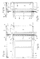
- Figures 4a and 4b show a further representation of the Invention in a side view and in a plan view. additionally to the features already described are in this Representation, in particular in FIG. 4b, guide systems 8 schematically shown, in which the base body (s) 4 are guided with the stops 4, 5 and possibly by own drive systems, not shown, can be created.
- the adjustability of the base body 4 is due to the Double file symbolically indicated to the right of Figure 4b.
- the base body 4 is for example sledge-like guided. It is particularly advantageous if the guidance system 8 is powered by a system in which all Drive systems are coupled such that the base body 4th Always drive in parallel and only one common one, not shown Have actuator 11, by means of which all Base body 4 are adjustable.
- FIG. 4a and 4b shows a special one Execution of the base body 4, or the base body 4, such that for the rear upper stop 6 and the lower front stop 5 interchangeable stop elements are provided are. These elements are then on the common body 4 positionable so that you have at least two stop surfaces receives, as already mentioned, in different levels or altitudes are arranged so that they in the respective height position adjustable by means of the lowering device 7 are.
- the stop elements are when there are signs of wear easily exchangeable. It doesn't have to be the whole Base body 4 to be replaced when a stop is damaged is.
- FIGS. 5a and 5b show a further embodiment of the Invention with additional stop rails 10.
- the stop rail 10 connects at least two base bodies 4, either the front stops 5 or the rear upper stops 6.
- the stop rail 10 serves to support the parallel cutting of short parts or workpieces, which cannot be applied to two stops at the same time are.
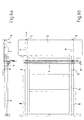
- FIGS. 6a and 6b show an enlarged illustration of the Embodiment according to Figure 4 can be seen.
- the base body 4 are positioned as far as on the saw blade 1, that the lower front stop 5 on the saw blade 1 is applied. This position can be used, for example, to now workpieces in width between the saw blade 1 and the rear upper stop 6 for example for cutting too to lead.
- This setting can also be used to for example, slots in thicker workpieces W with a certain depth.
Landscapes
- Life Sciences & Earth Sciences (AREA)
- Engineering & Computer Science (AREA)
- Mechanical Engineering (AREA)
- Wood Science & Technology (AREA)
- Forests & Forestry (AREA)
- Milling, Drilling, And Turning Of Wood (AREA)
Abstract
Description
- Fig. 1
- eine Seitenansicht des erfindungsgemäßen Anschlagsystems mit Grundkörper in abgesenkter Stellung;
- Fig. 2
- eine Seitenansicht mit Grundkörper in einer ersten angehobenen Stellung;
- Fig. 3
- eine Seitenansicht mit Grundkörper in einer zweiten angehobenen Stellung;
- Fig. 4 a, b
- weitere Darstellung der Erfindung mit Führungssystem;
- Fig. 5 a, b
- weitere Ausführungsform der Erfindung mit Anschlagschiene;
- Fig. 6 a, b
- vergrößerte Darstellung der Ausführungsform nach Fig. 4.
Claims (11)
- Holzbearbeitungsmaschine, insbesondere Formatsäge mit einem Anschlagsystem, wobei das von einem Bearbeitungswerkzeug zu bearbeitende Werkstück auf der Auflagefläche (A) eines Auflagetisches aufliegt, mit mehreren Anschlägen zur Führung des Werkstückes (W), wobei mindestens ein Anschlag (5) aus der Auflagefläche (A) wegbewegbar ist, dadurch gekennzeichnet, daß zumindest zwei Anschläge (5, 6) gemeinsam an einem Grundkörper (4) des Anschlagsystems angeordnet sind und die Anschläge (5, 6) durch eine Bewegung des Grundkörpers (4) in oder aus der Auflagefläche (A) bewegbar sind.
- Holzbearbeitungsmaschine nach Anspruch 1, dadurch gekennzeichnet, daß die Anschläge (5, 6) des Grundkörpers (4) mit unterschiedlichem Abstand zum Bearbeitungswerkzeug (1) und in unterschiedlichen Lagen, insbesondere Höhenoder Winkellagen, am Grundkörper (4) angeordnet sind.
- Holzbearbeitungsmaschine nach einem oder beiden vorhergehenden Ansprüche, dadurch gekennzeichnet, daß der Grundkörper (4) drehbar oder longitudinal bewegbar, insbesondere rechtwinklig zur Auflagefläche (A) anheb- oder absenkbar ist.
- Holzbearbeitungsmaschine nach einem oder mehreren der vorhergehenden Ansprüche, dadurch gekennzeichnet, daß mehrere Anschläge (5, 6) auf mindestens einem Grundkörper (4) angeordnet sind, derart, daß der Anschlag (5), welcher den geringsten Abstand zum Bearbeitungswerkzeug besitzt, in der untersten Höhenlage im Bezug zur Arbeitsebene (A) und der Anschlag (6) mit einem größeren Abstand zum Bearbeitungswerkzeug in einer weiteren, höheren Höhenlage angeordnet ist.
- Holzbearbeitungsmaschine nach einem oder mehreren der vorhergehenden Ansprüche, dadurch gekennzeichnet, daß mehrere Grundkörper (4) vorgesehen sind, deren Abstand gegenüber dem Bearbeitungswerkzeug verstellbar beziehungsweise einstellbar ist und/oder wenigstens zwei Grundkörper (4) durch ein gemeinsames Verstellsystem in ihrem Abstand gegenüber dem Bearbeitungswerkzeug verstellbar sind.
- Holzbearbeitungsmaschine nach einem oder mehreren der vorhergehenden Ansprüche, dadurch gekennzeichnet, daß eine Absenkvorrichtung (7) zur Absenkung mindestens eines Grundkörpers (4) vorgesehen ist und/oder mehrere Grundkörper (4) über eine gemeinsame Absenkvorrichtung (7) in unterschiedliche Höhenlagen absenkbar beziehungsweise anhebbar sind und/oder wenigstens drei Höhenlagen mittels der Absenkvorrichtung (7) eingestellbar sind.
- Holzbearbeitungsmaschine nach einem oder mehreren der vorhergehenden Ansprüche, dadurch gekennzeichnet, daß eine Absenkvorrichtung ein Drehen des Grundkörpers (4) um eine, bevorzugt parallel zur Auflagefläche (A) orientierte Drehachse erlaubt und dadurch die Anschläge des Grundkörpers in oder aus der Auflagefläche (A) bewegt.
- Holzbearbeitungsmaschine nach einem oder mehreren der vorhergehenden Ansprüche, dadurch gekennzeichnet, daß die Absenkvorrichtung (7) für den Grundkörper (4) eine Absenkmechanik aufweist, die als Kniehebelmechanismus, mit über Gelenke (13) verstellbaren Kniehebeln (12) mit einer zusätzlichen Rastposition ausgeführt ist, und die über ein Bedienelement (11) bedienbar ist und/oder die Absenkvorrichtung (7) durch eine Zahnstange oder eine Gewindespindel mit jeweils einem Bedienelement angegeben ist und/oder ein Pneumatik- oder Hydraulikzylinder die Absenkvorrichtung (7) bildet.
- Holzbearbeitungsmaschine nach einem oder mehreren der vorhergehenden Ansprüche, dadurch gekennzeichnet, daß mindestens zwei Grundkörper (4) vorgesehen sind, die durch wenigstens eine Anschlagschiene (10) miteinander verbunden sind und/oder zwei Anschlagschienen (10) vorgesehen sind, die wenigstens zwei Grundkörper (4) korrespondierend am unteren, vorderen Anschlag (5) sowie am oberen, hinteren Anschlag (6) miteinander verbinden.
- Holzbearbeitungsmaschine nach einem oder mehreren der vorhergehenden Ansprüche, gekennzeichnet durch jeweils ein Führungssystem, bestehend aus Führungen (8) für jeden Grundkörper (4) und/oder jeweils ein Antriebssystem für jeden Grundkörper (4) und/oder daß der Grundkörper (4) in einem Führungssystem (8) insbesondere schlittenartig beweglich geführt und gelagert ist.
- Holzbearbeitungsmaschine nach einem oder mehreren der vorhergehenden Ansprüche, dadurch gekennzeichnet, daß die Antriebssysteme für die Grundkörper (4) derart gekoppelt sind, daß diese stets parallel fahren und nur ein gemeinsames Betätigungselement aufweisen und/oder das Antriebssystem für die Grundkörper (4) als Zahnstange mit Ritzel und die Koppelung als durchgehende, alle Ritzel verbindende Achse und das Betätigungselement als Handrad ausgeführt ist und/oder jeweils ein Klemmsystem für jeden Grundkörper (4) vorgesehen ist, wobei vorzugsweise alle Klemmsysteme derart gekoppelt sind, daß sie ein gemeinsames Betätigungselement aufweisen und stets zusammen geklemmt oder gelöst werden und/oder das Antriebssystem für den Grundkörper (4) beziehungsweise die Anschläge (5, 6) selbsthemmend ausgebildet ist.
Applications Claiming Priority (2)
| Application Number | Priority Date | Filing Date | Title |
|---|---|---|---|
| DE10301885A DE10301885A1 (de) | 2003-01-17 | 2003-01-17 | Anschlagsystem |
| DE10301885 | 2003-01-17 |
Publications (2)
| Publication Number | Publication Date |
|---|---|
| EP1439044A1 true EP1439044A1 (de) | 2004-07-21 |
| EP1439044B1 EP1439044B1 (de) | 2006-09-06 |
Family
ID=32520037
Family Applications (1)
| Application Number | Title | Priority Date | Filing Date |
|---|---|---|---|
| EP04000838A Expired - Lifetime EP1439044B1 (de) | 2003-01-17 | 2004-01-16 | Holzbearbeitungsmaschine mit Anschlagsystem |
Country Status (3)
| Country | Link |
|---|---|
| EP (1) | EP1439044B1 (de) |
| AT (1) | ATE338616T1 (de) |
| DE (2) | DE10301885A1 (de) |
Cited By (1)
| Publication number | Priority date | Publication date | Assignee | Title |
|---|---|---|---|---|
| EP2832507A1 (de) * | 2013-07-29 | 2015-02-04 | Schelling Anlagenbau GmbH | Verfahren zum Zersägen von Werkstücken |
Families Citing this family (2)
| Publication number | Priority date | Publication date | Assignee | Title |
|---|---|---|---|---|
| DE102006004901A1 (de) * | 2006-02-01 | 2007-08-23 | Otto Martin Maschinenbau Gmbh & Co. Kg | Anschlag für eine Bearbeitungsmaschine |
| DE102024119768A1 (de) * | 2024-07-11 | 2026-01-15 | Homag Gmbh | Ausrichteinrichtung |
Citations (4)
| Publication number | Priority date | Publication date | Assignee | Title |
|---|---|---|---|---|
| US1737131A (en) * | 1927-09-27 | 1929-11-26 | Tompkins Robert Osband | Saw-table gauge |
| CH305792A (de) * | 1952-04-10 | 1955-03-15 | Baumgartner Max | Anschlageinrichtung an Holzbearbeitungsmaschinen. |
| US4397598A (en) * | 1980-03-21 | 1983-08-09 | Firma Schelling & Co. | Apparatus for alignment of large planar members at feed tables of machine tools |
| DE10208071A1 (de) * | 2001-04-27 | 2002-10-31 | Otto Martin Maschb Gmbh & Co | Parallelanschlagsvorrichtung für einen Sägetisch |
Family Cites Families (3)
| Publication number | Priority date | Publication date | Assignee | Title |
|---|---|---|---|---|
| DE3637713C2 (de) * | 1986-11-05 | 1996-02-08 | Sbr Maschinen Handelsgesellsch | Positioniereinrichtung für platten- oder stabförmige Werkstücke in Bearbeitungsmaschinen |
| DE19529570A1 (de) * | 1995-08-11 | 1997-02-20 | Reinhardt Gmbh Maschbau | Werkstückanschlageinrichtung |
| IT1289822B1 (it) * | 1996-12-31 | 1998-10-16 | Biesse Spa | Macchina utensile per la lavorazione di pannelli. |
-
2003
- 2003-01-17 DE DE10301885A patent/DE10301885A1/de not_active Withdrawn
-
2004
- 2004-01-16 AT AT04000838T patent/ATE338616T1/de active
- 2004-01-16 EP EP04000838A patent/EP1439044B1/de not_active Expired - Lifetime
- 2004-01-16 DE DE502004001372T patent/DE502004001372D1/de not_active Expired - Lifetime
Patent Citations (4)
| Publication number | Priority date | Publication date | Assignee | Title |
|---|---|---|---|---|
| US1737131A (en) * | 1927-09-27 | 1929-11-26 | Tompkins Robert Osband | Saw-table gauge |
| CH305792A (de) * | 1952-04-10 | 1955-03-15 | Baumgartner Max | Anschlageinrichtung an Holzbearbeitungsmaschinen. |
| US4397598A (en) * | 1980-03-21 | 1983-08-09 | Firma Schelling & Co. | Apparatus for alignment of large planar members at feed tables of machine tools |
| DE10208071A1 (de) * | 2001-04-27 | 2002-10-31 | Otto Martin Maschb Gmbh & Co | Parallelanschlagsvorrichtung für einen Sägetisch |
Cited By (2)
| Publication number | Priority date | Publication date | Assignee | Title |
|---|---|---|---|---|
| EP2832507A1 (de) * | 2013-07-29 | 2015-02-04 | Schelling Anlagenbau GmbH | Verfahren zum Zersägen von Werkstücken |
| WO2015014423A1 (de) * | 2013-07-29 | 2015-02-05 | Schelling Anlagenbau Gmbh | Verfahren zum zersägen von werkstücks |
Also Published As
| Publication number | Publication date |
|---|---|
| ATE338616T1 (de) | 2006-09-15 |
| DE10301885A1 (de) | 2004-07-29 |
| DE502004001372D1 (de) | 2006-10-19 |
| EP1439044B1 (de) | 2006-09-06 |
Similar Documents
| Publication | Publication Date | Title |
|---|---|---|
| DE1427765C3 (de) | Führungseinrichtung für eine Betonschneidmaschine | |
| DE2915288C2 (de) | Kaltkreissäge mit einem schwenkbaren Sägeblattarm | |
| EP2181816B1 (de) | Bearbeitungsaggregat | |
| DE4332630A1 (de) | Vorrichtung zum spanabhebenden Erzeugung von Ausschnitten in Flächenelementen | |
| DE102019129535A1 (de) | Elektrische bearbeitungsmaschine | |
| DE3806116A1 (de) | Vorrichtung zum positionieren von bogenfoermigen kreuzsprossenrahmenteilen und zum fraesen von trapezfoermigen ausnehmungen in diese rahmenteile | |
| DE4243054C1 (de) | Vorrichtung zur Bearbeitung der Kantenränder von fortlaufend bewegten plattenförmigen Werkstücken | |
| EP1837110B1 (de) | Anschlagschiene mit doppelten, verfahrbaren Längsanschlägen | |
| EP1782931B1 (de) | Kantenfräsmaschine | |
| EP1593467B1 (de) | Vorrichtung zum Handhaben eines Stapels | |
| DE202019102750U1 (de) | Quertisch für eine Holzbearbeitungsmaschine und Holzbearbeitungsmaschine mit einem Quertisch | |
| DE102011101811B4 (de) | Profilschneideinrichtung | |
| EP1439044B1 (de) | Holzbearbeitungsmaschine mit Anschlagsystem | |
| EP0813941B2 (de) | Abbundanlage zur Bearbeitung von Strangmaterial | |
| DE4331246C2 (de) | Tisch-Kreissägemaschine | |
| EP3030370B1 (de) | Plattenaufteilanlage | |
| EP0816029B1 (de) | Abbundanlage zur Bearbeitung von stangenförmigen Holzwerkstücken | |
| DE3343787A1 (de) | Schweissraupenverputzmaschine mit verstellbaren anschlaegen fuer fensterrahmen od. dgl. aus kunststoff | |
| DE19611743C2 (de) | Sägevorrichtung zum stirnseitigen Zurichten von Fenstersprossen und dgl. Werkstücken | |
| DE102020005310A1 (de) | Fräsvorrichtung | |
| DE102013004201B4 (de) | Tragbare Maschine zur Bearbeitung von Ecken | |
| DE102012204309B4 (de) | Tischfräsmaschine | |
| DE1752820A1 (de) | Vorrichtung zur Bearbeitung eines Werkstueckes auf einer Drehbank durch gleichzeitigen Einstich mehrerer Meissel | |
| DE19536187C1 (de) | Transportable Tischkreissäge | |
| DE3315172C2 (de) |
Legal Events
| Date | Code | Title | Description |
|---|---|---|---|
| PUAI | Public reference made under article 153(3) epc to a published international application that has entered the european phase |
Free format text: ORIGINAL CODE: 0009012 |
|
| AK | Designated contracting states |
Kind code of ref document: A1 Designated state(s): AT BE BG CH CY CZ DE DK EE ES FI FR GB GR HU IE IT LI LU MC NL PT RO SE SI SK TR |
|
| AX | Request for extension of the european patent |
Extension state: AL LT LV MK |
|
| 17P | Request for examination filed |
Effective date: 20041228 |
|
| AKX | Designation fees paid |
Designated state(s): AT CH DE IT LI |
|
| 17Q | First examination report despatched |
Effective date: 20050321 |
|
| GRAP | Despatch of communication of intention to grant a patent |
Free format text: ORIGINAL CODE: EPIDOSNIGR1 |
|
| GRAS | Grant fee paid |
Free format text: ORIGINAL CODE: EPIDOSNIGR3 |
|
| GRAA | (expected) grant |
Free format text: ORIGINAL CODE: 0009210 |
|
| AK | Designated contracting states |
Kind code of ref document: B1 Designated state(s): AT CH DE IT LI |
|
| PG25 | Lapsed in a contracting state [announced via postgrant information from national office to epo] |
Ref country code: IT Free format text: LAPSE BECAUSE OF FAILURE TO SUBMIT A TRANSLATION OF THE DESCRIPTION OR TO PAY THE FEE WITHIN THE PRESCRIBED TIME-LIMIT;WARNING: LAPSES OF ITALIAN PATENTS WITH EFFECTIVE DATE BEFORE 2007 MAY HAVE OCCURRED AT ANY TIME BEFORE 2007. THE CORRECT EFFECTIVE DATE MAY BE DIFFERENT FROM THE ONE RECORDED. Effective date: 20060906 |
|
| REG | Reference to a national code |
Ref country code: CH Ref legal event code: EP |
|
| REG | Reference to a national code |
Ref country code: CH Ref legal event code: NV Representative=s name: PA ALDO ROEMPLER |
|
| REF | Corresponds to: |
Ref document number: 502004001372 Country of ref document: DE Date of ref document: 20061019 Kind code of ref document: P |
|
| PLBE | No opposition filed within time limit |
Free format text: ORIGINAL CODE: 0009261 |
|
| STAA | Information on the status of an ep patent application or granted ep patent |
Free format text: STATUS: NO OPPOSITION FILED WITHIN TIME LIMIT |
|
| 26N | No opposition filed |
Effective date: 20070607 |
|
| REG | Reference to a national code |
Ref country code: CH Ref legal event code: PCAR Free format text: ALDO ROEMPLER PATENTANWALT;BRENDENWEG 11 POSTFACH 154;9424 RHEINECK (CH) |
|
| PGFP | Annual fee paid to national office [announced via postgrant information from national office to epo] |
Ref country code: CH Payment date: 20100416 Year of fee payment: 7 |
|
| REG | Reference to a national code |
Ref country code: CH Ref legal event code: PL |
|
| PG25 | Lapsed in a contracting state [announced via postgrant information from national office to epo] |
Ref country code: CH Free format text: LAPSE BECAUSE OF NON-PAYMENT OF DUE FEES Effective date: 20110131 Ref country code: LI Free format text: LAPSE BECAUSE OF NON-PAYMENT OF DUE FEES Effective date: 20110131 |
|
| PGFP | Annual fee paid to national office [announced via postgrant information from national office to epo] |
Ref country code: IT Payment date: 20120125 Year of fee payment: 9 |
|
| PGFP | Annual fee paid to national office [announced via postgrant information from national office to epo] |
Ref country code: AT Payment date: 20130108 Year of fee payment: 10 |
|
| REG | Reference to a national code |
Ref country code: AT Ref legal event code: MM01 Ref document number: 338616 Country of ref document: AT Kind code of ref document: T Effective date: 20140116 |
|
| PG25 | Lapsed in a contracting state [announced via postgrant information from national office to epo] |
Ref country code: AT Free format text: LAPSE BECAUSE OF NON-PAYMENT OF DUE FEES Effective date: 20140116 |
|
| PGFP | Annual fee paid to national office [announced via postgrant information from national office to epo] |
Ref country code: DE Payment date: 20150328 Year of fee payment: 12 |
|
| PG25 | Lapsed in a contracting state [announced via postgrant information from national office to epo] |
Ref country code: IT Free format text: LAPSE BECAUSE OF NON-PAYMENT OF DUE FEES Effective date: 20140116 |
|
| REG | Reference to a national code |
Ref country code: DE Ref legal event code: R119 Ref document number: 502004001372 Country of ref document: DE |
|
| PG25 | Lapsed in a contracting state [announced via postgrant information from national office to epo] |
Ref country code: DE Free format text: LAPSE BECAUSE OF NON-PAYMENT OF DUE FEES Effective date: 20160802 |