EP1438552B1 - Procede de calcul d'un signal de niveau de remplissage temporel - Google Patents
Procede de calcul d'un signal de niveau de remplissage temporel Download PDFInfo
- Publication number
- EP1438552B1 EP1438552B1 EP02762249A EP02762249A EP1438552B1 EP 1438552 B1 EP1438552 B1 EP 1438552B1 EP 02762249 A EP02762249 A EP 02762249A EP 02762249 A EP02762249 A EP 02762249A EP 1438552 B1 EP1438552 B1 EP 1438552B1
- Authority
- EP
- European Patent Office
- Prior art keywords
- filling level
- signal
- liquid
- sensor
- level
- Prior art date
- Legal status (The legal status is an assumption and is not a legal conclusion. Google has not performed a legal analysis and makes no representation as to the accuracy of the status listed.)
- Expired - Lifetime
Links
- 238000000034 method Methods 0.000 title claims description 20
- 230000002123 temporal effect Effects 0.000 title description 13
- 239000007788 liquid Substances 0.000 claims description 60
- 239000010705 motor oil Substances 0.000 claims description 14
- 238000002485 combustion reaction Methods 0.000 claims description 9
- 238000005259 measurement Methods 0.000 claims description 7
- 230000001419 dependent effect Effects 0.000 claims description 5
- 230000000694 effects Effects 0.000 claims description 4
- 239000000463 material Substances 0.000 description 7
- 238000010586 diagram Methods 0.000 description 4
- 238000012935 Averaging Methods 0.000 description 3
- 239000006185 dispersion Substances 0.000 description 3
- 230000003068 static effect Effects 0.000 description 3
- 238000004364 calculation method Methods 0.000 description 2
- 238000001514 detection method Methods 0.000 description 1
- 239000000446 fuel Substances 0.000 description 1
- 238000009736 wetting Methods 0.000 description 1
Images

Classifications
-
- G—PHYSICS
- G01—MEASURING; TESTING
- G01F—MEASURING VOLUME, VOLUME FLOW, MASS FLOW OR LIQUID LEVEL; METERING BY VOLUME
- G01F23/00—Indicating or measuring liquid level or level of fluent solid material, e.g. indicating in terms of volume or indicating by means of an alarm
- G01F23/22—Indicating or measuring liquid level or level of fluent solid material, e.g. indicating in terms of volume or indicating by means of an alarm by measuring physical variables, other than linear dimensions, pressure or weight, dependent on the level to be measured, e.g. by difference of heat transfer of steam or water
- G01F23/24—Indicating or measuring liquid level or level of fluent solid material, e.g. indicating in terms of volume or indicating by means of an alarm by measuring physical variables, other than linear dimensions, pressure or weight, dependent on the level to be measured, e.g. by difference of heat transfer of steam or water by measuring variations of resistance of resistors due to contact with conductor fluid
-
- G—PHYSICS
- G01—MEASURING; TESTING
- G01F—MEASURING VOLUME, VOLUME FLOW, MASS FLOW OR LIQUID LEVEL; METERING BY VOLUME
- G01F23/00—Indicating or measuring liquid level or level of fluent solid material, e.g. indicating in terms of volume or indicating by means of an alarm
- G01F23/22—Indicating or measuring liquid level or level of fluent solid material, e.g. indicating in terms of volume or indicating by means of an alarm by measuring physical variables, other than linear dimensions, pressure or weight, dependent on the level to be measured, e.g. by difference of heat transfer of steam or water
- G01F23/26—Indicating or measuring liquid level or level of fluent solid material, e.g. indicating in terms of volume or indicating by means of an alarm by measuring physical variables, other than linear dimensions, pressure or weight, dependent on the level to be measured, e.g. by difference of heat transfer of steam or water by measuring variations of capacity or inductance of capacitors or inductors arising from the presence of liquid or fluent solid material in the electric or electromagnetic fields
- G01F23/263—Indicating or measuring liquid level or level of fluent solid material, e.g. indicating in terms of volume or indicating by means of an alarm by measuring physical variables, other than linear dimensions, pressure or weight, dependent on the level to be measured, e.g. by difference of heat transfer of steam or water by measuring variations of capacity or inductance of capacitors or inductors arising from the presence of liquid or fluent solid material in the electric or electromagnetic fields by measuring variations in capacitance of capacitors
- G01F23/266—Indicating or measuring liquid level or level of fluent solid material, e.g. indicating in terms of volume or indicating by means of an alarm by measuring physical variables, other than linear dimensions, pressure or weight, dependent on the level to be measured, e.g. by difference of heat transfer of steam or water by measuring variations of capacity or inductance of capacitors or inductors arising from the presence of liquid or fluent solid material in the electric or electromagnetic fields by measuring variations in capacitance of capacitors measuring circuits therefor
-
- G—PHYSICS
- G01—MEASURING; TESTING
- G01F—MEASURING VOLUME, VOLUME FLOW, MASS FLOW OR LIQUID LEVEL; METERING BY VOLUME
- G01F23/00—Indicating or measuring liquid level or level of fluent solid material, e.g. indicating in terms of volume or indicating by means of an alarm
- G01F23/80—Arrangements for signal processing
- G01F23/806—Particular electronic circuits for handling non-digital processing equipment
- G01F23/808—Particular electronic circuits for handling non-digital processing equipment containing circuits handling parameters other than liquid level
-
- Y—GENERAL TAGGING OF NEW TECHNOLOGICAL DEVELOPMENTS; GENERAL TAGGING OF CROSS-SECTIONAL TECHNOLOGIES SPANNING OVER SEVERAL SECTIONS OF THE IPC; TECHNICAL SUBJECTS COVERED BY FORMER USPC CROSS-REFERENCE ART COLLECTIONS [XRACs] AND DIGESTS
- Y10—TECHNICAL SUBJECTS COVERED BY FORMER USPC
- Y10S—TECHNICAL SUBJECTS COVERED BY FORMER USPC CROSS-REFERENCE ART COLLECTIONS [XRACs] AND DIGESTS
- Y10S438/00—Semiconductor device manufacturing: process
- Y10S438/907—Continuous processing
Definitions
- the invention relates to a method for calculating a time level signal from a sensor signal of a level sensor for detecting the level of a liquid level.
- the invention further relates to a level measuring system with at least one level sensor for detecting the level of a liquid level and a computing unit for calculating a time level signal from the sensor signal of the at least one level sensor for performing the method.
- Fill level measuring systems with level sensors immersed in a liquid are used in particular in motor vehicles and are well known.
- the detection of the level of the liquid takes place for example with capacitive level sensors, wherein the capacitance of the sensor structures is influenced by the liquid level and by the dielectric properties of the liquid.
- the level sensors are designed as elongated sensors, which are occupied along the sensor to be detected by the fill level range. Particularly in the case of highly viscous liquids, the problem arises when the liquid level fluctuates that a liquid film forms on briefly wetted sensor surfaces. This liquid film causes z. B. in analog capacitive or thermal level sensors a positive error signal. The sensor signal for calculating the current fill level is then too large due to the remaining liquid film.
- the object of the invention is therefore to provide an improved, generic method for calculating a time level signal from a sensor signal of a level sensor, with which the level can be determined much more accurate.
- the temporal level signal is calculated as a function of the sensor signal and the flow behavior of the liquid at the level sensor according to the method defined in claim 1.
- the error is considered, which is caused by the forming liquid films.
- the flow behavior of the liquid is modeled by the surface of the level sensor and used together with the sensor signal as a function for calculating the time level signal.
- the model for the flow behavior of the liquid at the level sensor should essentially depend on the material properties of the liquid, such as. As viscosity and density, the material properties of the level sensor, in particular the surface condition, as well as external influences, such as the temperature of the liquid to be dependent. These parameters can either be preset or determined by additional sensors.
- the function for calculating the temporal level signal further depends on the modeled effects of a liquid film on the level sensor on the sensor signal.
- the function can, for. B. consider the inhomogeneity of a liquid film with.
- the correction signal is a function of time fluctuations of the fill level.
- the correction signal thus depends on the last observed fluctuations in the level. These fluctuations can z.
- B are characterized by a current temporal dispersion ⁇ (s), so that the correction signal can be a function of the current temporal dispersion.
- the correction signal may be a function of the viscosity of the liquid, the density of the liquid and / or the temperature of the liquid, etc.
- a time level signal of engine oil in an internal combustion engine is further proposed to add the amount of circulating in the engine amount of engine oil to the determined level signal.
- the circulating amount can be determined as a function of the speed of the engine and the temperature of the engine oil.
- the object is further achieved by the level measuring system according to claim 8, which is designed for carrying out the method described above.
- FIG. 1 1 shows a schematic sketch of a fill level measuring system which essentially has a fill level sensor 1 and a computing unit 2 for calculating a temporal fill level signal h (t) from the sensor signal s (t) of the fill level sensor 1.
- the temporal level signal h (t) is displayed on a display unit 3.
- the level sensor 1 is constructed in a known manner as an elongate sensor which is immersed in a liquid 4 in a container 5.
- the sensor has a sensor structure in the level range to be detected.
- the level sensor 1 is designed as a capacitive sensor with a comb-like interlocking structure.
- the liquid 4 fluctuates z. B. in moving container 5 or motor vehicle, in which the container 5 is installed. This leads to a likewise fluctuating time profile of the filling level sensor signal s (t).
- the arithmetic unit 2 is now designed so that from the time profile of the sensor signal s (t) of the level sensor 1, the actual time profile of the level, that is, the level signal h (t) or its running time average H (t) (approximately) is calculated.
- the method for calculating the level signal h (t) uses an algorithm based on a model for the runoff behavior of the liquid, 4 on the liquid sensor 1. This model depends inter alia on the material properties of the liquid 4, such as viscosity and density, the material properties of the liquid sensor 1, in particular the surface texture, as well as external influences, such as. B. the temperature of the liquid 4 from. The temperature of the liquid 4 may, for. B.
- the viscosity ⁇ and the density ⁇ are either given as a sensor signal to the arithmetic unit 2 or are preset values.
- the arithmetic unit 2 is z. B. by appropriate programming so that the time level signal h (t) is calculated as a function of the sensor signal s (t) and the modeled flow behavior of the liquid 4 at the level sensor 1 at least approximately. Furthermore, the function for calculating the temporal level signal h (t) from the modeled effects of a liquid film adhering to the level sensor 1 is dependent on the sensor signal s (t).
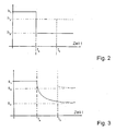
- the FIG. 2 shows a diagram of an idealized, time-hopping changing level signal h (t) over time t.
- FIG. 3 shows a diagram of the level of the signal h (t) associated sensor signal s (t), which is received by the level sensor 1.
- the associated "static" sensor signal s 1 is set .
- the filling level jumps abruptly to the value h 2. Due to the liquid film running on the surface of the elongate filling level sensor 1, the sensor signal s (t) follows the sudden drop in the liquid level only with a delay, so that the associated static sensor signal s 2 only after appropriate time, for example asymptotically sets.
- the level signal h (t) increases abruptly to the level h 3 . Since the level sensor 1 is wetted immediately, the sensor signal s (t) follows this sudden increase in the level very quickly. Since h in the illustrated case, the fill up level 3 below the fill level h 1 is located, results in an "overshoot" of the sensor signal s (t) over the h to the fill up level 3 belonging static value s 3, because the level sensor 1 in the filling level range h 3 to h 1 is still covered with a liquid film residue of the wetting before the time t a .
- the time t corresponds to the time interval considered during the averaging.
- a model for the flow behavior of the liquid 4 at the level sensor 1 and a model for the effect of a possibly inhomogeneous liquid film on the sensor signal s (t) is taken into account.
- the flow behavior of the liquid 4 at the level sensor 1 depends inter alia on the Material properties of the liquid, such as. As viscosity ⁇ and density ⁇ from.
- the flow behavior is further due to the material properties of the level sensor 1, such. B. the surface texture, and external influences; how the temperature of the liquid is determined.
- the sensor signal s (t) is present and it is the time-level signal h (t) or its means H ( t ) be determined. This is achieved by inversion of the F function.
- a particularly simple method according to the invention provides that a corrected time level signal h (t) is obtained by subtracting a correction signal ⁇ s from the above measured average level signal s ( t ) is calculated.
- the correction value ⁇ s is thus dependent on the scattering ⁇ (s), viscosity ⁇ , the density ⁇ , the temperature T, etc.
- the method is particularly suitable for determining the level of engine oil in an internal combustion engine, since the liquid film from the engine oil proceeds only slowly on the surface of a level sensor 1.
- the additional problem arises that there is always a certain amount of engine oil in circulation while the internal combustion engine is running. It is therefore additionally proposed to add to the level signal h (t) or the sensor signal s (t) a value representing the amount of engine oil in circulation. This value is determined, in particular, as a function of the speed of the internal combustion engine and the temperature Temp of the engine oil.
Landscapes
- Physics & Mathematics (AREA)
- Engineering & Computer Science (AREA)
- Fluid Mechanics (AREA)
- General Physics & Mathematics (AREA)
- Signal Processing (AREA)
- Thermal Sciences (AREA)
- Power Engineering (AREA)
- Electromagnetism (AREA)
- Measurement Of Levels Of Liquids Or Fluent Solid Materials (AREA)
- Lubrication Details And Ventilation Of Internal Combustion Engines (AREA)
- Light Receiving Elements (AREA)
Claims (10)
- Procédé de calcul d'un signal de niveau de remplissage temporel (h(t)) à partir d'un signal de capteur (s(t)) d'un capteur de niveau de remplissage (1), pour la détection du niveau de remplissage d'un liquide (4), caractérisé en ce que le signal de niveau de remplissage temporel (h(t)) est calculé sous forme de fonction du signal de capteur (s(t)) et du comportement modélisé d'écoulement du liquide (4) au niveau du capteur de niveau de remplissage (1).
- Procédé selon la revendication 1, caractérisé en ce que le comportement d'écoulement est modélisé en fonction des paramètres de viscosité (η) du liquide, de densité (ρ) du liquide, de constitution superficielle du capteur de liquide et/ou de température (Temp) du liquide.
- Procédé selon la revendication 1 ou 2, caractérisé en ce que la fonction de calcul du signal de niveau de remplissage temporel (h(t)) dépend en outre des effets modélisés qu'un film de liquide sur le capteur de niveau de remplissage (1) a sur le signal de capteur (s(t)).
- Procédé selon l'une quelconque des revendications précédentes, caractérisé par la soustraction d'un signal de correction (Δ
s ) d'un signal de capteur mesuré moyen (s(t)), le signal de correction (Δs ) étant une fonction de variations temporelles du niveau de remplissage. - Procédé selon la revendication 4, caractérisé en ce que le signal de correction (Δ
s ) est une fonction de la dispersion temporelle courante (σ(s)). - Procédé selon la revendication 4 ou 5, caractérisé en ce que le signal de correction (Δ
s ) est une fonction de la viscosité (η) du liquide, de la densité (ρ) du liquide et/ou de la température (Temp) du liquide. - Procédé selon l'une quelconque des revendications précédentes, pour le calcul d'un signal de niveau de remplissage temporel (h(t)) d'huile de moteur dans un moteur à combustion interne, caractérisé par l'addition d'une quantité d'huile de moteur circulant dans le moteur à combustion interne au signal de niveau de remplissage temporel (h(t)) détecté, la quantité en circulation étant déterminée en tant que fonction du régime du moteur à combustion interne et de la température de l'huile de moteur.
- Système de mesure du niveau de remplissage comprenant au moins un capteur de niveau de remplissage (1) pour détecter le niveau de remplissage d'un liquide (4) et une unité de calcul (2) pour calculer un signal de niveau de remplissage temporel (h(t)) à partir du signal de capteur (s(t)) de l'au moins un capteur de niveau de remplissage (1), caractérisé en ce que le système de mesure du niveau de remplissage est réalisé pour mettre en oeuvre le procédé selon l'une quelconque des revendications précédentes.
- Système de mesure du niveau de remplissage selon la revendication 8, caractérisé en ce que le système de mesure du niveau de remplissage peut être raccordé à un capteur de température (6) pour déterminer la température (Temp) du liquide et déterminer le signal de niveau de remplissage temporel (h(t)) en fonction de la température (Temp).
- Système de mesure du niveau de remplissage selon l'une quelconque des revendications 8 ou 9, pour le calcul d'un signal de niveau de remplissage temporel (h(t)) d'huile de moteur dans un moteur à combustion interne, caractérisé en ce que le système de mesure du niveau de remplissage peut être raccordé à un appareil de mesure de régime pour déterminer le régime du moteur à combustion interne et déterminer le signal du niveau de remplissage d'huile de moteur temporel en fonction du régime.
Applications Claiming Priority (3)
| Application Number | Priority Date | Filing Date | Title |
|---|---|---|---|
| DE10144875 | 2001-09-12 | ||
| DE10144875A DE10144875A1 (de) | 2001-09-12 | 2001-09-12 | Verfahren zur Berechnung eines zeitlichen Füllstandssignals |
| PCT/DE2002/003117 WO2003025521A1 (fr) | 2001-09-12 | 2002-08-24 | Procede de calcul d'un signal de niveau de remplissage temporel |
Publications (2)
| Publication Number | Publication Date |
|---|---|
| EP1438552A1 EP1438552A1 (fr) | 2004-07-21 |
| EP1438552B1 true EP1438552B1 (fr) | 2009-07-22 |
Family
ID=7698741
Family Applications (1)
| Application Number | Title | Priority Date | Filing Date |
|---|---|---|---|
| EP02762249A Expired - Lifetime EP1438552B1 (fr) | 2001-09-12 | 2002-08-24 | Procede de calcul d'un signal de niveau de remplissage temporel |
Country Status (5)
| Country | Link |
|---|---|
| US (1) | US6924214B2 (fr) |
| EP (1) | EP1438552B1 (fr) |
| JP (1) | JP4109195B2 (fr) |
| DE (2) | DE10144875A1 (fr) |
| WO (1) | WO2003025521A1 (fr) |
Families Citing this family (12)
| Publication number | Priority date | Publication date | Assignee | Title |
|---|---|---|---|---|
| DE102004054625A1 (de) * | 2004-11-11 | 2006-05-18 | Mann + Hummel Gmbh | Widerstandsheizung |
| US7701027B1 (en) * | 2005-03-04 | 2010-04-20 | Hrl Laboratories, Llc | Method and apparatus for reduction of non-adaptive signals in photo-EMF sensors |
| EP2072762B1 (fr) * | 2007-12-21 | 2012-05-30 | Techspace Aero SA | Méthode de contrôle de la consommation et de détection de fuites dans un système de lubrification de turbomachine |
| DE102008003802A1 (de) * | 2008-01-10 | 2009-07-16 | Robert Bosch Gmbh | Kapazitiver Füllstandsensor und Verfahren zum Schätzen eines Füllstandes |
| DE102009040588A1 (de) * | 2009-09-08 | 2011-03-10 | Volkswagen Ag | Verfahren zur Bestimmung eines Ölfüllstandes |
| US8955776B2 (en) * | 2010-02-26 | 2015-02-17 | Alstom Technology Ltd | Method of constructing a stationary coal nozzle |
| ITMI20111865A1 (it) * | 2011-10-13 | 2013-04-14 | Idrabel Italia S R L | Apparati e metodi di mappatura di vasi |
| KR101888608B1 (ko) * | 2014-10-17 | 2018-09-20 | 엘지이노텍 주식회사 | 발광 소자 패키지 및 조명 장치 |
| CN110022705A (zh) * | 2016-12-22 | 2019-07-16 | 菲利普莫里斯生产公司 | 具有电极对的气溶胶生成系统 |
| MX2019009868A (es) | 2017-02-28 | 2019-12-02 | Philip Morris Products Sa | Sistema generador de aerosol con electrodos y sensores. |
| JP2020153304A (ja) * | 2019-03-20 | 2020-09-24 | ヤンマーパワーテクノロジー株式会社 | エンジン |
| JP7674083B2 (ja) | 2020-08-26 | 2025-05-09 | 浜松ホトニクス株式会社 | 光検出装置 |
Family Cites Families (6)
| Publication number | Priority date | Publication date | Assignee | Title |
|---|---|---|---|---|
| US2982908A (en) * | 1957-11-12 | 1961-05-02 | Honeywell Regulator Co | Sensing apparatus |
| FR1389869A (fr) | 1964-03-24 | 1965-02-19 | Dispositif formant sonde ou analogue pour le contrôle de niveau de liquides électroconducteurs dans un réservoir et ses diverses applications | |
| CH546285A (de) * | 1971-12-22 | 1974-02-28 | Zellweger Uster Ag | Verfahren und vorrichtung zur steuerung des fuellungsgrades von bandspeichern in der textilindustrie, insbesondere in spinnerei. |
| JP3555100B2 (ja) * | 1997-02-04 | 2004-08-18 | 株式会社リコー | 液体現像剤の濃度調整装置及び画像形成装置 |
| US6202483B1 (en) * | 1997-05-05 | 2001-03-20 | Richard D. Barcus | Volumetric flow metering apparatus |
| DE19944331B4 (de) | 1999-09-15 | 2006-03-30 | Fraunhofer-Gesellschaft zur Förderung der angewandten Forschung e.V. | Mikrosensoranordnung zur Positionsmessung von Flüssigkeiten in Kapillaren |
-
2001
- 2001-09-12 DE DE10144875A patent/DE10144875A1/de not_active Ceased
-
2002
- 2002-08-24 US US10/416,109 patent/US6924214B2/en not_active Expired - Fee Related
- 2002-08-24 WO PCT/DE2002/003117 patent/WO2003025521A1/fr not_active Ceased
- 2002-08-24 EP EP02762249A patent/EP1438552B1/fr not_active Expired - Lifetime
- 2002-08-24 DE DE50213708T patent/DE50213708D1/de not_active Expired - Lifetime
- 2002-08-24 JP JP2003529102A patent/JP4109195B2/ja not_active Expired - Fee Related
Also Published As
| Publication number | Publication date |
|---|---|
| JP4109195B2 (ja) | 2008-07-02 |
| US6924214B2 (en) | 2005-08-02 |
| WO2003025521A1 (fr) | 2003-03-27 |
| DE10144875A1 (de) | 2003-03-27 |
| DE50213708D1 (de) | 2009-09-03 |
| JP2005502894A (ja) | 2005-01-27 |
| EP1438552A1 (fr) | 2004-07-21 |
| US20040029366A1 (en) | 2004-02-12 |
Similar Documents
| Publication | Publication Date | Title |
|---|---|---|
| EP0786584B1 (fr) | Procédé de détermination d'une quantité de liquide notamment la quantité d'huile, dans un véhicule automobile | |
| EP1438552B1 (fr) | Procede de calcul d'un signal de niveau de remplissage temporel | |
| DE69909472T2 (de) | Vorrichtung zum schätzen des ladungszustands einer batterie und verfahren zum schätzen des abnutzungszustands einer batterie | |
| DE2928767C2 (de) | Verfahren zur Bestimmung der Vorratsmenge von Betriebsflüssigkeiten von Kraftfahrzeugen und Schaltung zur Ausführung des Verfahrens | |
| EP1259714B1 (fr) | Procede permettant d'evaluer l'usure d'huile de moteur | |
| DE102010033335B4 (de) | Verfahren zum Ermitteln der Sauerstoffspeicherkapazität eines einem Katalysator zugeordneten Sauerstoffspeichers | |
| DE102007030992A1 (de) | Verfahren und Vorrichtung zur Tankfüllstandserfassung | |
| DE10010976A1 (de) | Verfahren zur Beurteilung des Verschleißes von Motoröl unter Berücksichtigung einer Frischölnachfüllung | |
| EP3077650B1 (fr) | Procédé de surveillance d'un capteur de gaz d'échappement | |
| DE102013109783B4 (de) | Verfahren zum Verhindern einer Fehldiagnose eines Ölstandsensors | |
| DE112008000257T5 (de) | Hochdrucktank-Temperaturdetektionssystem und Hochdruck-Tanksystem | |
| DE102010043358A1 (de) | Verfahren und Systeme zur Thermistortemperaturverarbeitung | |
| DE112011104607T5 (de) | Automatikgetriebe-Steuereinrichtung | |
| DE102009056331A1 (de) | Wasserstoffsensor sowie Erfassungsverfahren einer Wasserstoffkonzentration | |
| DE19929295A1 (de) | Verfahren und Vorrichtung zur Bestimmung der Flüssigkeitsmenge in einem bewegten Behälter | |
| EP1364189B1 (fr) | Procede permettant de determiner le niveau d'un produit de fonctionnement dans un vehicule a moteur | |
| DE102016222849B4 (de) | Verfahren zur Kalibrierung einer Anzeige eines Füllstands | |
| DE102012020455B4 (de) | Geschwindigkeitsüberwachungsvorrichtung | |
| DE19955972C2 (de) | Verfahren zum Kalibrieren eines Temperatursensors | |
| DE69119184T2 (de) | Elektronisches Medizinalthermometer | |
| DE102006053100A1 (de) | Verfahren zur Bestimmung der an einem resistiven Partikelsensor herrschenden Temperatur | |
| DE102022107492B3 (de) | Verfahren zum Abschätzen einer Bauteillebensdauer und Kraftfahrzeug | |
| DE102014223945A1 (de) | Traktionsbatterie eines Elektrofahrzeugs umfassend ein Flüssigkeitsdetektionssystem und Verfahren zum Erkennen einer Standhöhe einer Flüssigkeit in der Traktionsbatterie | |
| EP2815246B1 (fr) | Procédé de détermination d'un courant, unité de gestion de batterie, batterie et véhicule automobile | |
| DE102018211116B4 (de) | Verfahren zum Betreiben einer Antriebseinrichtung für ein Kraftfahrzeug sowie entsprechende Antriebseinrichtung |
Legal Events
| Date | Code | Title | Description |
|---|---|---|---|
| PUAI | Public reference made under article 153(3) epc to a published international application that has entered the european phase |
Free format text: ORIGINAL CODE: 0009012 |
|
| 17P | Request for examination filed |
Effective date: 20040413 |
|
| AK | Designated contracting states |
Kind code of ref document: A1 Designated state(s): AT BE BG CH CY CZ DE DK EE ES FI FR GB GR IE IT LI LU MC NL PT SE SK TR |
|
| GRAP | Despatch of communication of intention to grant a patent |
Free format text: ORIGINAL CODE: EPIDOSNIGR1 |
|
| GRAS | Grant fee paid |
Free format text: ORIGINAL CODE: EPIDOSNIGR3 |
|
| GRAA | (expected) grant |
Free format text: ORIGINAL CODE: 0009210 |
|
| AK | Designated contracting states |
Kind code of ref document: B1 Designated state(s): DE FR GB |
|
| REG | Reference to a national code |
Ref country code: GB Ref legal event code: FG4D Free format text: NOT ENGLISH |
|
| REF | Corresponds to: |
Ref document number: 50213708 Country of ref document: DE Date of ref document: 20090903 Kind code of ref document: P |
|
| PLBE | No opposition filed within time limit |
Free format text: ORIGINAL CODE: 0009261 |
|
| STAA | Information on the status of an ep patent application or granted ep patent |
Free format text: STATUS: NO OPPOSITION FILED WITHIN TIME LIMIT |
|
| 26N | No opposition filed |
Effective date: 20100423 |
|
| PGFP | Annual fee paid to national office [announced via postgrant information from national office to epo] |
Ref country code: GB Payment date: 20140821 Year of fee payment: 13 Ref country code: FR Payment date: 20140819 Year of fee payment: 13 |
|
| PGFP | Annual fee paid to national office [announced via postgrant information from national office to epo] |
Ref country code: DE Payment date: 20141024 Year of fee payment: 13 |
|
| REG | Reference to a national code |
Ref country code: DE Ref legal event code: R119 Ref document number: 50213708 Country of ref document: DE |
|
| GBPC | Gb: european patent ceased through non-payment of renewal fee |
Effective date: 20150824 |
|
| REG | Reference to a national code |
Ref country code: FR Ref legal event code: ST Effective date: 20160429 |
|
| PG25 | Lapsed in a contracting state [announced via postgrant information from national office to epo] |
Ref country code: GB Free format text: LAPSE BECAUSE OF NON-PAYMENT OF DUE FEES Effective date: 20150824 Ref country code: DE Free format text: LAPSE BECAUSE OF NON-PAYMENT OF DUE FEES Effective date: 20160301 |
|
| PG25 | Lapsed in a contracting state [announced via postgrant information from national office to epo] |
Ref country code: FR Free format text: LAPSE BECAUSE OF NON-PAYMENT OF DUE FEES Effective date: 20150831 |