EP1438552B1 - Method for calculating a temporal level signal - Google Patents
Method for calculating a temporal level signal Download PDFInfo
- Publication number
- EP1438552B1 EP1438552B1 EP02762249A EP02762249A EP1438552B1 EP 1438552 B1 EP1438552 B1 EP 1438552B1 EP 02762249 A EP02762249 A EP 02762249A EP 02762249 A EP02762249 A EP 02762249A EP 1438552 B1 EP1438552 B1 EP 1438552B1
- Authority
- EP
- European Patent Office
- Prior art keywords
- filling level
- signal
- liquid
- sensor
- level
- Prior art date
- Legal status (The legal status is an assumption and is not a legal conclusion. Google has not performed a legal analysis and makes no representation as to the accuracy of the status listed.)
- Expired - Lifetime
Links
- 238000000034 method Methods 0.000 title claims description 20
- 230000002123 temporal effect Effects 0.000 title description 13
- 239000007788 liquid Substances 0.000 claims description 60
- 239000010705 motor oil Substances 0.000 claims description 14
- 238000002485 combustion reaction Methods 0.000 claims description 9
- 238000005259 measurement Methods 0.000 claims description 7
- 230000001419 dependent effect Effects 0.000 claims description 5
- 230000000694 effects Effects 0.000 claims description 4
- 239000000463 material Substances 0.000 description 7
- 238000010586 diagram Methods 0.000 description 4
- 238000012935 Averaging Methods 0.000 description 3
- 239000006185 dispersion Substances 0.000 description 3
- 230000003068 static effect Effects 0.000 description 3
- 238000004364 calculation method Methods 0.000 description 2
- 238000001514 detection method Methods 0.000 description 1
- 239000000446 fuel Substances 0.000 description 1
- 238000009736 wetting Methods 0.000 description 1
Images

Classifications
-
- G—PHYSICS
- G01—MEASURING; TESTING
- G01F—MEASURING VOLUME, VOLUME FLOW, MASS FLOW OR LIQUID LEVEL; METERING BY VOLUME
- G01F23/00—Indicating or measuring liquid level or level of fluent solid material, e.g. indicating in terms of volume or indicating by means of an alarm
- G01F23/22—Indicating or measuring liquid level or level of fluent solid material, e.g. indicating in terms of volume or indicating by means of an alarm by measuring physical variables, other than linear dimensions, pressure or weight, dependent on the level to be measured, e.g. by difference of heat transfer of steam or water
- G01F23/24—Indicating or measuring liquid level or level of fluent solid material, e.g. indicating in terms of volume or indicating by means of an alarm by measuring physical variables, other than linear dimensions, pressure or weight, dependent on the level to be measured, e.g. by difference of heat transfer of steam or water by measuring variations of resistance of resistors due to contact with conductor fluid
-
- G—PHYSICS
- G01—MEASURING; TESTING
- G01F—MEASURING VOLUME, VOLUME FLOW, MASS FLOW OR LIQUID LEVEL; METERING BY VOLUME
- G01F23/00—Indicating or measuring liquid level or level of fluent solid material, e.g. indicating in terms of volume or indicating by means of an alarm
- G01F23/22—Indicating or measuring liquid level or level of fluent solid material, e.g. indicating in terms of volume or indicating by means of an alarm by measuring physical variables, other than linear dimensions, pressure or weight, dependent on the level to be measured, e.g. by difference of heat transfer of steam or water
- G01F23/26—Indicating or measuring liquid level or level of fluent solid material, e.g. indicating in terms of volume or indicating by means of an alarm by measuring physical variables, other than linear dimensions, pressure or weight, dependent on the level to be measured, e.g. by difference of heat transfer of steam or water by measuring variations of capacity or inductance of capacitors or inductors arising from the presence of liquid or fluent solid material in the electric or electromagnetic fields
- G01F23/263—Indicating or measuring liquid level or level of fluent solid material, e.g. indicating in terms of volume or indicating by means of an alarm by measuring physical variables, other than linear dimensions, pressure or weight, dependent on the level to be measured, e.g. by difference of heat transfer of steam or water by measuring variations of capacity or inductance of capacitors or inductors arising from the presence of liquid or fluent solid material in the electric or electromagnetic fields by measuring variations in capacitance of capacitors
- G01F23/266—Indicating or measuring liquid level or level of fluent solid material, e.g. indicating in terms of volume or indicating by means of an alarm by measuring physical variables, other than linear dimensions, pressure or weight, dependent on the level to be measured, e.g. by difference of heat transfer of steam or water by measuring variations of capacity or inductance of capacitors or inductors arising from the presence of liquid or fluent solid material in the electric or electromagnetic fields by measuring variations in capacitance of capacitors measuring circuits therefor
-
- G—PHYSICS
- G01—MEASURING; TESTING
- G01F—MEASURING VOLUME, VOLUME FLOW, MASS FLOW OR LIQUID LEVEL; METERING BY VOLUME
- G01F23/00—Indicating or measuring liquid level or level of fluent solid material, e.g. indicating in terms of volume or indicating by means of an alarm
- G01F23/80—Arrangements for signal processing
- G01F23/806—Particular electronic circuits for handling non-digital processing equipment
- G01F23/808—Particular electronic circuits for handling non-digital processing equipment containing circuits handling parameters other than liquid level
-
- Y—GENERAL TAGGING OF NEW TECHNOLOGICAL DEVELOPMENTS; GENERAL TAGGING OF CROSS-SECTIONAL TECHNOLOGIES SPANNING OVER SEVERAL SECTIONS OF THE IPC; TECHNICAL SUBJECTS COVERED BY FORMER USPC CROSS-REFERENCE ART COLLECTIONS [XRACs] AND DIGESTS
- Y10—TECHNICAL SUBJECTS COVERED BY FORMER USPC
- Y10S—TECHNICAL SUBJECTS COVERED BY FORMER USPC CROSS-REFERENCE ART COLLECTIONS [XRACs] AND DIGESTS
- Y10S438/00—Semiconductor device manufacturing: process
- Y10S438/907—Continuous processing
Definitions
- the invention relates to a method for calculating a time level signal from a sensor signal of a level sensor for detecting the level of a liquid level.
- the invention further relates to a level measuring system with at least one level sensor for detecting the level of a liquid level and a computing unit for calculating a time level signal from the sensor signal of the at least one level sensor for performing the method.
- Fill level measuring systems with level sensors immersed in a liquid are used in particular in motor vehicles and are well known.
- the detection of the level of the liquid takes place for example with capacitive level sensors, wherein the capacitance of the sensor structures is influenced by the liquid level and by the dielectric properties of the liquid.
- the level sensors are designed as elongated sensors, which are occupied along the sensor to be detected by the fill level range. Particularly in the case of highly viscous liquids, the problem arises when the liquid level fluctuates that a liquid film forms on briefly wetted sensor surfaces. This liquid film causes z. B. in analog capacitive or thermal level sensors a positive error signal. The sensor signal for calculating the current fill level is then too large due to the remaining liquid film.
- the object of the invention is therefore to provide an improved, generic method for calculating a time level signal from a sensor signal of a level sensor, with which the level can be determined much more accurate.
- the temporal level signal is calculated as a function of the sensor signal and the flow behavior of the liquid at the level sensor according to the method defined in claim 1.
- the error is considered, which is caused by the forming liquid films.
- the flow behavior of the liquid is modeled by the surface of the level sensor and used together with the sensor signal as a function for calculating the time level signal.
- the model for the flow behavior of the liquid at the level sensor should essentially depend on the material properties of the liquid, such as. As viscosity and density, the material properties of the level sensor, in particular the surface condition, as well as external influences, such as the temperature of the liquid to be dependent. These parameters can either be preset or determined by additional sensors.
- the function for calculating the temporal level signal further depends on the modeled effects of a liquid film on the level sensor on the sensor signal.
- the function can, for. B. consider the inhomogeneity of a liquid film with.
- the correction signal is a function of time fluctuations of the fill level.
- the correction signal thus depends on the last observed fluctuations in the level. These fluctuations can z.
- B are characterized by a current temporal dispersion ⁇ (s), so that the correction signal can be a function of the current temporal dispersion.
- the correction signal may be a function of the viscosity of the liquid, the density of the liquid and / or the temperature of the liquid, etc.
- a time level signal of engine oil in an internal combustion engine is further proposed to add the amount of circulating in the engine amount of engine oil to the determined level signal.
- the circulating amount can be determined as a function of the speed of the engine and the temperature of the engine oil.
- the object is further achieved by the level measuring system according to claim 8, which is designed for carrying out the method described above.
- FIG. 1 1 shows a schematic sketch of a fill level measuring system which essentially has a fill level sensor 1 and a computing unit 2 for calculating a temporal fill level signal h (t) from the sensor signal s (t) of the fill level sensor 1.
- the temporal level signal h (t) is displayed on a display unit 3.
- the level sensor 1 is constructed in a known manner as an elongate sensor which is immersed in a liquid 4 in a container 5.
- the sensor has a sensor structure in the level range to be detected.
- the level sensor 1 is designed as a capacitive sensor with a comb-like interlocking structure.
- the liquid 4 fluctuates z. B. in moving container 5 or motor vehicle, in which the container 5 is installed. This leads to a likewise fluctuating time profile of the filling level sensor signal s (t).
- the arithmetic unit 2 is now designed so that from the time profile of the sensor signal s (t) of the level sensor 1, the actual time profile of the level, that is, the level signal h (t) or its running time average H (t) (approximately) is calculated.
- the method for calculating the level signal h (t) uses an algorithm based on a model for the runoff behavior of the liquid, 4 on the liquid sensor 1. This model depends inter alia on the material properties of the liquid 4, such as viscosity and density, the material properties of the liquid sensor 1, in particular the surface texture, as well as external influences, such as. B. the temperature of the liquid 4 from. The temperature of the liquid 4 may, for. B.
- the viscosity ⁇ and the density ⁇ are either given as a sensor signal to the arithmetic unit 2 or are preset values.
- the arithmetic unit 2 is z. B. by appropriate programming so that the time level signal h (t) is calculated as a function of the sensor signal s (t) and the modeled flow behavior of the liquid 4 at the level sensor 1 at least approximately. Furthermore, the function for calculating the temporal level signal h (t) from the modeled effects of a liquid film adhering to the level sensor 1 is dependent on the sensor signal s (t).
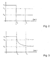
- the FIG. 2 shows a diagram of an idealized, time-hopping changing level signal h (t) over time t.
- FIG. 3 shows a diagram of the level of the signal h (t) associated sensor signal s (t), which is received by the level sensor 1.
- the associated "static" sensor signal s 1 is set .
- the filling level jumps abruptly to the value h 2. Due to the liquid film running on the surface of the elongate filling level sensor 1, the sensor signal s (t) follows the sudden drop in the liquid level only with a delay, so that the associated static sensor signal s 2 only after appropriate time, for example asymptotically sets.
- the level signal h (t) increases abruptly to the level h 3 . Since the level sensor 1 is wetted immediately, the sensor signal s (t) follows this sudden increase in the level very quickly. Since h in the illustrated case, the fill up level 3 below the fill level h 1 is located, results in an "overshoot" of the sensor signal s (t) over the h to the fill up level 3 belonging static value s 3, because the level sensor 1 in the filling level range h 3 to h 1 is still covered with a liquid film residue of the wetting before the time t a .
- the time t corresponds to the time interval considered during the averaging.
- a model for the flow behavior of the liquid 4 at the level sensor 1 and a model for the effect of a possibly inhomogeneous liquid film on the sensor signal s (t) is taken into account.
- the flow behavior of the liquid 4 at the level sensor 1 depends inter alia on the Material properties of the liquid, such as. As viscosity ⁇ and density ⁇ from.
- the flow behavior is further due to the material properties of the level sensor 1, such. B. the surface texture, and external influences; how the temperature of the liquid is determined.
- the sensor signal s (t) is present and it is the time-level signal h (t) or its means H ( t ) be determined. This is achieved by inversion of the F function.
- a particularly simple method according to the invention provides that a corrected time level signal h (t) is obtained by subtracting a correction signal ⁇ s from the above measured average level signal s ( t ) is calculated.
- the correction value ⁇ s is thus dependent on the scattering ⁇ (s), viscosity ⁇ , the density ⁇ , the temperature T, etc.
- the method is particularly suitable for determining the level of engine oil in an internal combustion engine, since the liquid film from the engine oil proceeds only slowly on the surface of a level sensor 1.
- the additional problem arises that there is always a certain amount of engine oil in circulation while the internal combustion engine is running. It is therefore additionally proposed to add to the level signal h (t) or the sensor signal s (t) a value representing the amount of engine oil in circulation. This value is determined, in particular, as a function of the speed of the internal combustion engine and the temperature Temp of the engine oil.
Landscapes
- Physics & Mathematics (AREA)
- Engineering & Computer Science (AREA)
- Fluid Mechanics (AREA)
- General Physics & Mathematics (AREA)
- Signal Processing (AREA)
- Thermal Sciences (AREA)
- Power Engineering (AREA)
- Electromagnetism (AREA)
- Measurement Of Levels Of Liquids Or Fluent Solid Materials (AREA)
- Lubrication Details And Ventilation Of Internal Combustion Engines (AREA)
- Light Receiving Elements (AREA)
Description
Die Erfindung betrifft ein Verfahren zur Berechnung eines zeitlichen Füllstandssignals aus einem Sensorsignal eines Füllstandssensors zur Detektion des Füllstandspegels einer Flüssigkeit.The invention relates to a method for calculating a time level signal from a sensor signal of a level sensor for detecting the level of a liquid level.
Die Erfindung betrifft weiterhin ein Füllstandsmeßsystem mit mindestens einem Füllstandssensor zur Detektion des Füllstandspegels einer Flüssigkeit und einer Recheneinheit zur Berechnung eines zeitlichen Füllstandssignals aus dem Sensorsignal des mindestens einen Füllstandssensors zur Durchführung des Verfahrens.The invention further relates to a level measuring system with at least one level sensor for detecting the level of a liquid level and a computing unit for calculating a time level signal from the sensor signal of the at least one level sensor for performing the method.
Füllstandsmeßsysteme mit Füllstandssensoren, die in eine Flüssigkeit eingetaucht sind, werden insbesondere in Kraftfahrzeugen eingesetzt und sind hinreichend bekannt. Die Detektion des Füllstands der Flüssigkeit erfolgt beispielsweise mit kapazitiven Füllstandssensoren, wobei die Kapazität der Sensorstrukturen durch den Flüssigkeitspegel sowie durch die dielektrischen Eigenschaften der Flüssigkeit beeinflusst wird.Fill level measuring systems with level sensors immersed in a liquid are used in particular in motor vehicles and are well known. The detection of the level of the liquid takes place for example with capacitive level sensors, wherein the capacitance of the sensor structures is influenced by the liquid level and by the dielectric properties of the liquid.
Bei der Bestimmung eines zeitlichen Füllstandssignals ergibt sich oftmals jedoch das Problem, dass der Füllstand, z. B. bei bewegtem Kraftfahrzeug erheblich schwankt.When determining a temporal level signal, however, often results in the problem that the level, z. B. varies considerably when the vehicle is moving.
In der Regel wird daher eine zeitliche Ermittlung des resultierenden Füllstandssignals vorgenommen, um die vorhandene Flüssigkeitsmenge, wie. z. B. Motoröl- oder Treibstoffmenge, abzuschätzen.In general, therefore, a temporal determination of the resulting level signal is made to the existing amount of liquid, such as. z. As engine oil or fuel quantity to estimate.
Die Füllstandssensoren sind als längliche Fühler ausgebildet, die entlang des zur detektierenden Füllstandspegelbereiches mit Sensorstrukturen belegt sind. Insbesondere bei hochviskosen Flüssigkeiten ergibt sich bei schwankendem Flüssigkeitsstand das Problem, dass sich ein Flüssigkeitsfilm auf kurzzeitig benetzten Sensoroberflächen ausbildet. Dieser Flüssigkeitsfilm verursacht z. B. bei analogen kapazitiven oder thermischen Füllstandssensoren ein positives Fehlersignal. Das Sensorsignal zur Berechnung des momentanen Füllstandspegels ist dann aufgrund des zurückbleibenden Flüssigkeitsfilms zu groß.The level sensors are designed as elongated sensors, which are occupied along the sensor to be detected by the fill level range. Particularly in the case of highly viscous liquids, the problem arises when the liquid level fluctuates that a liquid film forms on briefly wetted sensor surfaces. This liquid film causes z. B. in analog capacitive or thermal level sensors a positive error signal. The sensor signal for calculating the current fill level is then too large due to the remaining liquid film.
Nach einiger Zeit laufen diese Flüssigkeitsfilme in Abhängigkeit von den Flüssigkeitseigenschaften, wie Dichte und Viskosität, wieder ab. Hierdurch verschwindet das Fehlersignal. Bei schwankendem Füllstandspegel wird dieser Flüssigkeitsfilm jedoch regelmäßig erneuert, so dass ein gemitteltes zeitliches Füllstandssignal einen positiven Fehler aufweist.After some time, these liquid films, depending on the liquid properties, such as density and viscosity, again. As a result, the error signal disappears. However, when the fill level fluctuates, this liquid film is renewed regularly, so that an averaged time level signal has a positive error.
Aufgabe der Erfindung war es daher, ein verbessertes, gattungsgemäßes Verfahren zur Berechnung eines zeitlichen Füllstandssignals aus einem Sensorsignal eines Füllstandssensors zu schaffen, mit dem der Füllstand wesentlich genauer bestimmt werden kann.The object of the invention is therefore to provide an improved, generic method for calculating a time level signal from a sensor signal of a level sensor, with which the level can be determined much more accurate.
Die Aufgabe wird erfindungsgemäß dadurch gelöst, dass das zeitliche Füllstandssignal als Funktion des Sensorsignals und des Ablaufverhaltens der Flüssigkeit am Füllstandssensor nach dem im Anspruch 1 definiertes Verfahren berechnet wird.The object is achieved in that the temporal level signal is calculated as a function of the sensor signal and the flow behavior of the liquid at the level sensor according to the method defined in
Im Gegensatz zur herkömmlichen reinen zeitlichen Mittelung des Füllstandssignals bei der Füllstandsberechnung schwankender Flüssigkeitsmengen wird erfindungsgemäß der Fehler berücksichtigt, der durch die sich ausbildenden Flüssigkeitsfilme verursacht wird. Hierzu wird das Ablaufverhalten der Flüssigkeit von der Oberfläche des Füllstandssensors modelliert und zusammen mit dem Sensorsignal als Funktion zur Berechnung des zeitlichen Füllstandssignals verwendet.In contrast to the conventional pure time averaging of the level signal in the level calculation of fluctuating amounts of liquid according to the invention, the error is considered, which is caused by the forming liquid films. For this purpose, the flow behavior of the liquid is modeled by the surface of the level sensor and used together with the sensor signal as a function for calculating the time level signal.
Das Modell für das Ablaufverhalten der Flüssigkeit am Füllstandssensor sollte im wesentlichen von den Materialeigenschaften der Flüssigkeit, wie z. B. Viskosität und Dichte, den Materialeigenschaften des Füllstandssensors, insbesondere die Oberflächenbeschaffenheit, als auch von äußeren Einflüssen, wie die Temperatur der Flüssigkeit, abhängig sein. Diese Parameter können entweder voreingestellt oder durch weitere Sensoren bestimmt werden.The model for the flow behavior of the liquid at the level sensor should essentially depend on the material properties of the liquid, such as. As viscosity and density, the material properties of the level sensor, in particular the surface condition, as well as external influences, such as the temperature of the liquid to be dependent. These parameters can either be preset or determined by additional sensors.
In einer bevorzugten Ausbildung des Verfahrens ist die Funktion zur Berechnung des zeitlichen Füllstandssignals weiterhin von den modellierten Auswirkungen eines Flüssigkeitsfilms an dem Füllstandssensor auf das Sensorsignal abhängig. Die Funktion kann z. B. die Inhomogenität eines Flüssigkeitsfilms mit berücksichtigen.In a preferred embodiment of the method, the function for calculating the temporal level signal further depends on the modeled effects of a liquid film on the level sensor on the sensor signal. The function can, for. B. consider the inhomogeneity of a liquid film with.
Da das Systemverhalten in der Regel nichtlinear ist, erfolgt die Berechnung vorzugsweise durch entsprechende Näherungen. So ist es besonders vorteilhaft, ein Korrektursignal von dem zeitlich gemessenen Füllstandssignal zu substrahieren. Das Korrektursignal ist hierbei eine Funktion von zeitlichen Schwankungen des Füllstandspegels. Das Korrektursignal hängt somit von den zuletzt beobachteten Schwankungen des Füllstands ab. Diese Schwankungen können z. B durch eine laufende zeitliche Streuung σ(s) charakterisiert werden, so dass das Korrektursignal eine Funktion der laufenden zeitlichen Streuung sein kann.Since the system behavior is usually non-linear, the calculation is preferably done by appropriate approximations. Thus, it is particularly advantageous to subtract a correction signal from the time-measured level signal. The correction signal is a function of time fluctuations of the fill level. The correction signal thus depends on the last observed fluctuations in the level. These fluctuations can z. B are characterized by a current temporal dispersion σ (s), so that the correction signal can be a function of the current temporal dispersion.
Wie bereits oben erläutert, kann das Korrektursignal eine Funktion der Viskosität der Flüssigkeit, Dichte der Flüssigkeit und/oder Temperatur der Flüssigkeit etc. sein.As already explained above, the correction signal may be a function of the viscosity of the liquid, the density of the liquid and / or the temperature of the liquid, etc.
Zur Berechnung eines zeitlichen Füllstandssignals von Motoröl in einem Verbrennungsmotor wird weiterhin vorgeschlagen, das Maß einer im Verbrennungsmotor umlaufenden Menge von Motoröl auf das ermittelte Füllstandssignal zu addieren. Hierbei kann die umlaufende Menge als Funktion der Drehzahl des Verbrennungsmotors und der Temperatur des Motoröls bestimmt werden.To calculate a time level signal of engine oil in an internal combustion engine is further proposed to add the amount of circulating in the engine amount of engine oil to the determined level signal. Here, the circulating amount can be determined as a function of the speed of the engine and the temperature of the engine oil.
Die Aufgabe wird ferner durch das Füllstandsmeßsystem nach Anspruch 8 gelöst, das zur Durchführung des oben beschriebenen Verfahrens ausgebildet ist.The object is further achieved by the level measuring system according to claim 8, which is designed for carrying out the method described above.
Die Erfindung wird nachfolgend anhand der beigefügten Zeichnungen näher erläutert. Es zeigen:
- Figur 1 -
- Skizze eines Füllstandsmeßsystems zur Durchführung des erfindungsgemäßen Verfahrens;
- Figur 2 -
- Diagramm eines zeitlichen Füllstands bei sprungförmiger Füllstandsänderung;
- Figur 3 -
- Diagramm der zeitlichen Änderung des Füllstandssignals bei der sprungförmigen Füllstandsänderung aus
Figur 2
- FIG. 1 -
- Sketch of a level measuring system for carrying out the method according to the invention;
- FIG. 2 -
- Diagram of a time level with sudden changes in level;
- FIG. 3 -
- Diagram of the time change of the level signal during the sudden change in level
FIG. 2 ,
Die
Der Füllstandssensor 1 ist in bekannter Weise als länglicher Fühler aufgebaut, der in eine Flüssigkeit 4 in einem Behälter 5 eingetaucht ist. Der Fühler hat eine Sensorstruktur im zu detektierenden Füllstandspegelbereich. In dem dargestellten Beispiel ist der Füllstandssensor 1 als kapazitiver Sensor mit einer kammartig ineinandergreifenden Struktur ausgebildet.The
Die Flüssigkeit 4 schwankt z. B. bei bewegtem Behälter 5 oder Kraftfahrzeug, in das der Behälter 5 eingebaut ist. Dies führt zu einem ebenfalls schwankenden zeitlichen Verlauf des Füllstandssensorsignals s(t).The
Herkömmlicherweise wird eine zeitliche Mittelung des schwankenden Füllstands-Sensorsignals s(t) vorgenommen, um den tatsächlichen Füllstand der Flüssigkeit 4 in dem Behälter 5 zu bestimmen.Conventionally, an averaging of the fluctuating level sensor signal s (t) is made in order to determine the actual level of the
Erfindungsgemäß ist die Recheneinheit 2 nunmehr so ausgebildet, dass aus dem zeitlichen Verlauf des Sensorsignals s(t) des Füllstandssensors 1 der tatsächliche zeitliche Verlauf des Füllstands, das heißt, das Füllstandssignal h(t) oder dessen laufendes zeitliches Mittel
Die Recheneinheit 2 ist z. B. durch geeignete Programmierung so ausgebildet, dass das zeitliche Füllstandssignal h(t) als Funktion des Sensorsignals s(t) und des modellierten Ablaufverhaltens der Flüssigkeit 4 an dem Füllstandssensor 1 zumindest näherungsweise berechnet wird. Weiterhin ist die Funktion zur Berechnung des zeitlichen Füllstandssignals h(t) von den modellierten Auswirkungen eines Flüssigkeitsfilms, der an dem Füllstandssensor 1 haftet, auf das Sensorsignal s(t) abhängig.The
Diese funktionalen Zusammenhänge werden nachfolgend an einem Beispiel theoretisch weiter erläutert.These functional relationships will be further explained theoretically below using one example.
Die
Die
Unter der Annahme eines sehr lange konstant vorliegenden Füllstandes h1 stellt sich das zugehörige "statische" Sensorsignal s1 ein. Zum Zeitpunkt ta springt der Füllstand abrupt auf den Wert h2, Aufgrund des an der Oberfläche des länglichen Füllstandssensors 1 ablaufenden Flüssigkeitsfilms folgt das Sensorssignal s(t) dem sprunghaften Absinken des Flüssigkeitspegels nur mit Verzögerung, so dass sich das zugehörige statische Sensorsignal s2 erst nach entsprechender Zeit, beispielsweise asymptotisch einstellt.Assuming a very long constant level h 1 , the associated "static" sensor signal s 1 is set . At the time t a , the filling level jumps abruptly to the value h 2. Due to the liquid film running on the surface of the elongate
Im weiteren Verlauf ist mit gestrichelten Linien der Fall aufgezeigt, dass sich zur Zeit tb das Füllstandssignal h(t) abrupt auf den Füllstandspegel h3 erhöht. Da der Füllstandssensor 1 sofort benetzt wird, folgt das Sensorsignal s(t) diesem sprunghaften Anstieg des Füllstandspegels sehr schnell. Da in dem dargestellten Fall der Füllstandspegel h3 unterhalb des Füllstandspegels h1 liegt, ergibt sich ein "Überschießen" des Sensorssignals s(t) über den zu dem Füllstandspegel h3 gehörenden statischen Wert s3, da der Füllstandssensor 1 im Füllstandspegelbereich h3 bis h1 noch mit einem Flüssigkeitsfilmrest von der Benetzung vor dem Zeitpunkt ta bedeckt ist.In the further course of the case is shown with dashed lines that at time t b, the level signal h (t) increases abruptly to the level h 3 . Since the
Damit wird die Problematik deutlich, dass die Ansprechzeit des Sensorsignals s(t) bei positiven Füllstandsänderungen 

Das laufende zeitliche Mittel des Sensorsignals 
definiert werden.The current time average of the sensor signal
To be defined.
Die Zeit t entspricht dabei dem bei der Mittelung betrachteten Zeitintervall.The time t corresponds to the time interval considered during the averaging.
Um nun aus dem zeitlichen Verlauf des Sensorsignals s(t) einen korrekteren zeitlichen Verlauf des Füllstandspegels, das heißt ein verbessertes Füllstandssignal h(t) oder dessen laufendes zeitliches Mittel
Das Ablaufverhalten wird weiterhin durch die Materialeigenschaften des Füllstandssensors 1, wie z. B. der Oberflächenbeschaffenheit, und von äußeren Einflüssen; wie der Temperatur Temp der Flüssigkeit bestimmt.The flow behavior is further due to the material properties of the
Basierend auf diesen beiden Modellen kann aus einem gegebenen Füllstandsverlauf mit dem Füllstandssignal h(t) auf das Sensorsignal s(t) des Füllstandssensors 1 zurückgeschlossen werden. Formal analytisch kann dieser Zusammenhang durch die Formel beschrieben werden: ![]()
mit dem Funktional F und dem schwankungsabhängigen Füllstandssignal h(τ).Based on these two models, it is possible to deduce the sensor signal s (t) of the ![]()
with the functional F and the fluctuation-dependent level signal h (τ).
Bei der Füllstandsmessung liegt jedoch das Sensorsignal s(t) vor und es soll das zeitliche Füllstandssignal h(t) oder dessen Mittel
Diese Inversion ist jedoch je nach Modell aufgrund des in der Regel nichtlinearen Systemverhaltens entsprechend aufwendig oder sogar unmöglich. Für das Verfahren zur Berechnung des zeitlichen Füllstandssignals h(t) oder dessen Mittel
Ein besonders einfaches erfindungsgemäßes Verfahren sieht vor, dass ein korrigiertes zeitliches Füllstandssignal h(t) durch Subtrahieren eines Korrektursignals Δ 
analytisch charakterisiert werden.A particularly simple method according to the invention provides that a corrected time level signal h (t) is obtained by subtracting a correction signal Δ
be characterized analytically.
Das korrigierte zeitliche Füllstandssignal h(t) oder dessen Mittelwert 
bestimmt, wobei der Korrekturwert Δ ![]()
determined, wherein the correction value .DELTA ![]()
Der Korrekturwert Δ
Das Verfahren ist insbesondere zur Bestimmung des Füllstands von Motoröl in einem Verbrennungsmotor geeignet, da der Flüssigkeitsfilm vom Motoröl nur langsam an der Oberfläche eines Füllstandssensors 1 abläuft. In diesen und entsprechenden Anwendungsgebieten ergibt sich zusätzlich das Problem, dass sich immer bei laufendem Verbrennungsmotor eine bestimmte Motorölmenge im Umlauf befindet. Es wird daher zusätzlich vorgeschlagen, dem Füllstandssignal h(t) oder dem Sensorsignal s(t) einen Wert hinzuzurechnen, der die im Umlauf befindliche Motorölmenge repräsentiert. Dieser Wert wird insbesondere als Funktion der Drehzahl des Verbrennungsmotors und der Temperatur Temp des Motoröls bestimmt.The method is particularly suitable for determining the level of engine oil in an internal combustion engine, since the liquid film from the engine oil proceeds only slowly on the surface of a
Claims (10)
- Method for calculating a filling level time signal (h(t)) from a sensor signal (s(t)) of a filling level sensor (1) for detecting the filling level of a liquid (4), characterized in that the filling level time signal (h(t)) is calculated as a function of the sensor signal (s(t)) and the modelled outflow behaviour of the liquid (4) at the filling level sensor (1).
- Method according to Claim 1, characterized in that the outflow behaviour is modelled as a function of the following parameters: viscosity (η) of the liquid, the density (ρ) of the liquid, the surface condition of the liquid sensor and/or the temperature (Temp) of the liquid.
- Method according to Claim 1 or 2, characterized in that the function for calculating the filling level time signal (h(t)) is also dependent on the modelled effects of a liquid film over the filling level sensor (1) on the sensor signal (s(t)).
- Method according to one of the preceding claims, characterized by subtracting a correction signal (Δ
s ) from an average measured sensor signal (s (t)) , with the correction signal (Δs ) being a function of fluctuations in the filling level with respect to time. - Method according to Claim 4, characterized in that the correction signal (Δ
s ) is a function of the current time scatter (σ(s)). - Method according to Claim 4 or 5, characterized in that the correction signal (Δ
s ) is a function of the viscosity (η) of the liquid, the density (ρ) of the liquid and/or the temperature (Temp) of the liquid. - Method according one of the preceding claims for calculating a filling level time signal (h(t)) of engine oil in an internal combustion engine, characterized by adding a quantity of engine oil circulating in the internal combustion engine to the ascertained filling level signal (h(t)), with the circulating quantity being determined as a function of the rotation speed of the internal combustion engine and the temperature of the engine oil.
- Filling level measurement system having at least one filling level sensor (1) for detecting the filling level of a liquid (4) and a computer unit (2) for calculating a filling level time signal (h(t)) from the sensor signal (s(t)) of the at least one filling level sensor (1), characterized in that the filling level measurement system is designed to carry out the method according to one of the preceding claims.
- Filling level measurement system according to Claim 8, characterized in that the filing level measurement system can be connected to a temperature sensor (6) for ascertaining the temperature (Temp) of the liquid and determining the filling level time signal (h(t)) as a function of the temperature (Temp).
- Filling level measurement system according to either of Claims 8 and 9 for calculating a filling level time signal (h(t)) of engine oil in an internal combustion engine, characterized in that the filling level measurement system can be connected to a rotation speed measuring device for ascertaining the rotation speed of the internal combustion engine and determining the engine oil filling level time signal as a function of the rotation speed.
Applications Claiming Priority (3)
| Application Number | Priority Date | Filing Date | Title |
|---|---|---|---|
| DE10144875 | 2001-09-12 | ||
| DE10144875A DE10144875A1 (en) | 2001-09-12 | 2001-09-12 | Measurement of time varying liquid level, especially for measurement of the oil level in a combustion engine, whereby the effect of viscosity is compensated so that a too-high liquid level is not measured |
| PCT/DE2002/003117 WO2003025521A1 (en) | 2001-09-12 | 2002-08-24 | Method for calculating a temporal level signal |
Publications (2)
| Publication Number | Publication Date |
|---|---|
| EP1438552A1 EP1438552A1 (en) | 2004-07-21 |
| EP1438552B1 true EP1438552B1 (en) | 2009-07-22 |
Family
ID=7698741
Family Applications (1)
| Application Number | Title | Priority Date | Filing Date |
|---|---|---|---|
| EP02762249A Expired - Lifetime EP1438552B1 (en) | 2001-09-12 | 2002-08-24 | Method for calculating a temporal level signal |
Country Status (5)
| Country | Link |
|---|---|
| US (1) | US6924214B2 (en) |
| EP (1) | EP1438552B1 (en) |
| JP (1) | JP4109195B2 (en) |
| DE (2) | DE10144875A1 (en) |
| WO (1) | WO2003025521A1 (en) |
Families Citing this family (12)
| Publication number | Priority date | Publication date | Assignee | Title |
|---|---|---|---|---|
| DE102004054625A1 (en) * | 2004-11-11 | 2006-05-18 | Mann + Hummel Gmbh | resistance heating |
| US7701027B1 (en) * | 2005-03-04 | 2010-04-20 | Hrl Laboratories, Llc | Method and apparatus for reduction of non-adaptive signals in photo-EMF sensors |
| EP2072762B1 (en) * | 2007-12-21 | 2012-05-30 | Techspace Aero SA | Method for controlling consumption and detecting leaks in a turbomachine lubrication system |
| DE102008003802A1 (en) * | 2008-01-10 | 2009-07-16 | Robert Bosch Gmbh | Capacitive level sensor and method for estimating a level |
| DE102009040588A1 (en) * | 2009-09-08 | 2011-03-10 | Volkswagen Ag | Method for determining an oil level |
| US8955776B2 (en) * | 2010-02-26 | 2015-02-17 | Alstom Technology Ltd | Method of constructing a stationary coal nozzle |
| ITMI20111865A1 (en) * | 2011-10-13 | 2013-04-14 | Idrabel Italia S R L | SYSTEMS AND METHODS OF VASING MAPPING |
| KR101888608B1 (en) * | 2014-10-17 | 2018-09-20 | 엘지이노텍 주식회사 | Light emitting device package and lighting apparatus |
| CN110022705A (en) * | 2016-12-22 | 2019-07-16 | 菲利普莫里斯生产公司 | Aerosol with electrode pair generates system |
| MX2019009868A (en) | 2017-02-28 | 2019-12-02 | Philip Morris Products Sa | Aerosol-generating system with electrodes and sensors. |
| JP2020153304A (en) * | 2019-03-20 | 2020-09-24 | ヤンマーパワーテクノロジー株式会社 | engine |
| JP7674083B2 (en) | 2020-08-26 | 2025-05-09 | 浜松ホトニクス株式会社 | Photodetector |
Family Cites Families (6)
| Publication number | Priority date | Publication date | Assignee | Title |
|---|---|---|---|---|
| US2982908A (en) * | 1957-11-12 | 1961-05-02 | Honeywell Regulator Co | Sensing apparatus |
| FR1389869A (en) | 1964-03-24 | 1965-02-19 | Device forming a probe or the like for monitoring the level of electrically conductive liquids in a tank and its various applications | |
| CH546285A (en) * | 1971-12-22 | 1974-02-28 | Zellweger Uster Ag | METHOD AND DEVICE FOR CONTROLLING THE LEVEL OF FILLING OF TAPE STORAGE SYSTEMS IN THE TEXTILE INDUSTRY, IN PARTICULAR IN SPINNING. |
| JP3555100B2 (en) * | 1997-02-04 | 2004-08-18 | 株式会社リコー | Liquid developer concentration adjusting apparatus and image forming apparatus |
| US6202483B1 (en) * | 1997-05-05 | 2001-03-20 | Richard D. Barcus | Volumetric flow metering apparatus |
| DE19944331B4 (en) | 1999-09-15 | 2006-03-30 | Fraunhofer-Gesellschaft zur Förderung der angewandten Forschung e.V. | Microsensor arrangement for measuring the position of liquids in capillaries |
-
2001
- 2001-09-12 DE DE10144875A patent/DE10144875A1/en not_active Ceased
-
2002
- 2002-08-24 US US10/416,109 patent/US6924214B2/en not_active Expired - Fee Related
- 2002-08-24 WO PCT/DE2002/003117 patent/WO2003025521A1/en not_active Ceased
- 2002-08-24 EP EP02762249A patent/EP1438552B1/en not_active Expired - Lifetime
- 2002-08-24 DE DE50213708T patent/DE50213708D1/en not_active Expired - Lifetime
- 2002-08-24 JP JP2003529102A patent/JP4109195B2/en not_active Expired - Fee Related
Also Published As
| Publication number | Publication date |
|---|---|
| JP4109195B2 (en) | 2008-07-02 |
| US6924214B2 (en) | 2005-08-02 |
| WO2003025521A1 (en) | 2003-03-27 |
| DE10144875A1 (en) | 2003-03-27 |
| DE50213708D1 (en) | 2009-09-03 |
| JP2005502894A (en) | 2005-01-27 |
| EP1438552A1 (en) | 2004-07-21 |
| US20040029366A1 (en) | 2004-02-12 |
Similar Documents
| Publication | Publication Date | Title |
|---|---|---|
| EP0786584B1 (en) | Method for determining a liquid quantity, especially the quantity of oil, in a motor vehicle | |
| EP1438552B1 (en) | Method for calculating a temporal level signal | |
| DE69909472T2 (en) | DEVICE FOR ESTIMATING THE CHARGE CONDITION OF A BATTERY AND METHOD FOR ESTIMATING THE WEAR CONDITION OF A BATTERY | |
| DE2928767C2 (en) | Method for determining the supply quantity of operating fluids in motor vehicles and circuit for carrying out the method | |
| EP1259714B1 (en) | Method for determining motor oil wear | |
| DE102010033335B4 (en) | Method for determining the oxygen storage capacity of an oxygen storage device assigned to a catalyst | |
| DE102007030992A1 (en) | Method and device for tank level detection | |
| DE10010976A1 (en) | Engine oil degradation evaluation method provides correction of oil viscosity reference value when engine oil level is topped up with fresh oil | |
| EP3077650B1 (en) | Method for monitoring an exhaust sensor | |
| DE102013109783B4 (en) | Method for preventing misdiagnosis of an oil level sensor | |
| DE112008000257T5 (en) | High pressure tank temperature detection system and high pressure tank system | |
| DE102010043358A1 (en) | Thermistor temperature processing methods and systems | |
| DE112011104607T5 (en) | Automatic transmission control means | |
| DE102009056331A1 (en) | Hydrogen sensor and detection method of a hydrogen concentration | |
| DE19929295A1 (en) | Method and device for determining the amount of liquid in a moving container | |
| EP1364189B1 (en) | Method for determining the amount of an operating medium in a motor vehicle | |
| DE102016222849B4 (en) | Method for calibrating a level display | |
| DE102012020455B4 (en) | Speed monitoring device | |
| DE19955972C2 (en) | Procedure for calibrating a temperature sensor | |
| DE69119184T2 (en) | Electronic medical thermometer | |
| DE102006053100A1 (en) | Method for determining the temperature prevailing at a resistive particle sensor | |
| DE102022107492B3 (en) | Method for estimating a component lifetime and motor vehicle | |
| DE102014223945A1 (en) | A traction battery of an electric vehicle comprising a fluid detection system and method for detecting a fluid level in the traction battery | |
| EP2815246B1 (en) | Method for determining a current, battery management unit, battery and motor vehicle | |
| DE102018211116B4 (en) | Method for operating a drive device for a motor vehicle and corresponding drive device |
Legal Events
| Date | Code | Title | Description |
|---|---|---|---|
| PUAI | Public reference made under article 153(3) epc to a published international application that has entered the european phase |
Free format text: ORIGINAL CODE: 0009012 |
|
| 17P | Request for examination filed |
Effective date: 20040413 |
|
| AK | Designated contracting states |
Kind code of ref document: A1 Designated state(s): AT BE BG CH CY CZ DE DK EE ES FI FR GB GR IE IT LI LU MC NL PT SE SK TR |
|
| GRAP | Despatch of communication of intention to grant a patent |
Free format text: ORIGINAL CODE: EPIDOSNIGR1 |
|
| GRAS | Grant fee paid |
Free format text: ORIGINAL CODE: EPIDOSNIGR3 |
|
| GRAA | (expected) grant |
Free format text: ORIGINAL CODE: 0009210 |
|
| AK | Designated contracting states |
Kind code of ref document: B1 Designated state(s): DE FR GB |
|
| REG | Reference to a national code |
Ref country code: GB Ref legal event code: FG4D Free format text: NOT ENGLISH |
|
| REF | Corresponds to: |
Ref document number: 50213708 Country of ref document: DE Date of ref document: 20090903 Kind code of ref document: P |
|
| PLBE | No opposition filed within time limit |
Free format text: ORIGINAL CODE: 0009261 |
|
| STAA | Information on the status of an ep patent application or granted ep patent |
Free format text: STATUS: NO OPPOSITION FILED WITHIN TIME LIMIT |
|
| 26N | No opposition filed |
Effective date: 20100423 |
|
| PGFP | Annual fee paid to national office [announced via postgrant information from national office to epo] |
Ref country code: GB Payment date: 20140821 Year of fee payment: 13 Ref country code: FR Payment date: 20140819 Year of fee payment: 13 |
|
| PGFP | Annual fee paid to national office [announced via postgrant information from national office to epo] |
Ref country code: DE Payment date: 20141024 Year of fee payment: 13 |
|
| REG | Reference to a national code |
Ref country code: DE Ref legal event code: R119 Ref document number: 50213708 Country of ref document: DE |
|
| GBPC | Gb: european patent ceased through non-payment of renewal fee |
Effective date: 20150824 |
|
| REG | Reference to a national code |
Ref country code: FR Ref legal event code: ST Effective date: 20160429 |
|
| PG25 | Lapsed in a contracting state [announced via postgrant information from national office to epo] |
Ref country code: GB Free format text: LAPSE BECAUSE OF NON-PAYMENT OF DUE FEES Effective date: 20150824 Ref country code: DE Free format text: LAPSE BECAUSE OF NON-PAYMENT OF DUE FEES Effective date: 20160301 |
|
| PG25 | Lapsed in a contracting state [announced via postgrant information from national office to epo] |
Ref country code: FR Free format text: LAPSE BECAUSE OF NON-PAYMENT OF DUE FEES Effective date: 20150831 |