EP1437486A1 - Système de purification des gaz d'échappement d'un moteur à combustion interne - Google Patents
Système de purification des gaz d'échappement d'un moteur à combustion interne Download PDFInfo
- Publication number
- EP1437486A1 EP1437486A1 EP20040000175 EP04000175A EP1437486A1 EP 1437486 A1 EP1437486 A1 EP 1437486A1 EP 20040000175 EP20040000175 EP 20040000175 EP 04000175 A EP04000175 A EP 04000175A EP 1437486 A1 EP1437486 A1 EP 1437486A1
- Authority
- EP
- European Patent Office
- Prior art keywords
- reactivation
- collected
- filter
- exhaust gas
- dispersion condition
- Prior art date
- Legal status (The legal status is an assumption and is not a legal conclusion. Google has not performed a legal analysis and makes no representation as to the accuracy of the status listed.)
- Granted
Links
Images


Classifications
-
- F—MECHANICAL ENGINEERING; LIGHTING; HEATING; WEAPONS; BLASTING
- F02—COMBUSTION ENGINES; HOT-GAS OR COMBUSTION-PRODUCT ENGINE PLANTS
- F02D—CONTROLLING COMBUSTION ENGINES
- F02D41/00—Electrical control of supply of combustible mixture or its constituents
- F02D41/02—Circuit arrangements for generating control signals
- F02D41/14—Introducing closed-loop corrections
- F02D41/1438—Introducing closed-loop corrections using means for determining characteristics of the combustion gases; Sensors therefor
- F02D41/1444—Introducing closed-loop corrections using means for determining characteristics of the combustion gases; Sensors therefor characterised by the characteristics of the combustion gases
- F02D41/1448—Introducing closed-loop corrections using means for determining characteristics of the combustion gases; Sensors therefor characterised by the characteristics of the combustion gases the characteristics being an exhaust gas pressure
-
- F—MECHANICAL ENGINEERING; LIGHTING; HEATING; WEAPONS; BLASTING
- F01—MACHINES OR ENGINES IN GENERAL; ENGINE PLANTS IN GENERAL; STEAM ENGINES
- F01N—GAS-FLOW SILENCERS OR EXHAUST APPARATUS FOR MACHINES OR ENGINES IN GENERAL; GAS-FLOW SILENCERS OR EXHAUST APPARATUS FOR INTERNAL COMBUSTION ENGINES
- F01N3/00—Exhaust or silencing apparatus having means for purifying, rendering innocuous, or otherwise treating exhaust
- F01N3/02—Exhaust or silencing apparatus having means for purifying, rendering innocuous, or otherwise treating exhaust for cooling, or for removing solid constituents of, exhaust
- F01N3/021—Exhaust or silencing apparatus having means for purifying, rendering innocuous, or otherwise treating exhaust for cooling, or for removing solid constituents of, exhaust by means of filters
- F01N3/022—Exhaust or silencing apparatus having means for purifying, rendering innocuous, or otherwise treating exhaust for cooling, or for removing solid constituents of, exhaust by means of filters characterised by specially adapted filtering structure, e.g. honeycomb, mesh or fibrous
- F01N3/0222—Exhaust or silencing apparatus having means for purifying, rendering innocuous, or otherwise treating exhaust for cooling, or for removing solid constituents of, exhaust by means of filters characterised by specially adapted filtering structure, e.g. honeycomb, mesh or fibrous the structure being monolithic, e.g. honeycombs
-
- F—MECHANICAL ENGINEERING; LIGHTING; HEATING; WEAPONS; BLASTING
- F01—MACHINES OR ENGINES IN GENERAL; ENGINE PLANTS IN GENERAL; STEAM ENGINES
- F01N—GAS-FLOW SILENCERS OR EXHAUST APPARATUS FOR MACHINES OR ENGINES IN GENERAL; GAS-FLOW SILENCERS OR EXHAUST APPARATUS FOR INTERNAL COMBUSTION ENGINES
- F01N3/00—Exhaust or silencing apparatus having means for purifying, rendering innocuous, or otherwise treating exhaust
- F01N3/02—Exhaust or silencing apparatus having means for purifying, rendering innocuous, or otherwise treating exhaust for cooling, or for removing solid constituents of, exhaust
- F01N3/021—Exhaust or silencing apparatus having means for purifying, rendering innocuous, or otherwise treating exhaust for cooling, or for removing solid constituents of, exhaust by means of filters
- F01N3/023—Exhaust or silencing apparatus having means for purifying, rendering innocuous, or otherwise treating exhaust for cooling, or for removing solid constituents of, exhaust by means of filters using means for regenerating the filters, e.g. by burning trapped particles
-
- F—MECHANICAL ENGINEERING; LIGHTING; HEATING; WEAPONS; BLASTING
- F01—MACHINES OR ENGINES IN GENERAL; ENGINE PLANTS IN GENERAL; STEAM ENGINES
- F01N—GAS-FLOW SILENCERS OR EXHAUST APPARATUS FOR MACHINES OR ENGINES IN GENERAL; GAS-FLOW SILENCERS OR EXHAUST APPARATUS FOR INTERNAL COMBUSTION ENGINES
- F01N9/00—Electrical control of exhaust gas treating apparatus
- F01N9/002—Electrical control of exhaust gas treating apparatus of filter regeneration, e.g. detection of clogging
-
- F—MECHANICAL ENGINEERING; LIGHTING; HEATING; WEAPONS; BLASTING
- F02—COMBUSTION ENGINES; HOT-GAS OR COMBUSTION-PRODUCT ENGINE PLANTS
- F02D—CONTROLLING COMBUSTION ENGINES
- F02D41/00—Electrical control of supply of combustible mixture or its constituents
- F02D41/0002—Controlling intake air
- F02D41/0007—Controlling intake air for control of turbo-charged or super-charged engines
-
- F—MECHANICAL ENGINEERING; LIGHTING; HEATING; WEAPONS; BLASTING
- F02—COMBUSTION ENGINES; HOT-GAS OR COMBUSTION-PRODUCT ENGINE PLANTS
- F02D—CONTROLLING COMBUSTION ENGINES
- F02D41/00—Electrical control of supply of combustible mixture or its constituents
- F02D41/02—Circuit arrangements for generating control signals
- F02D41/021—Introducing corrections for particular conditions exterior to the engine
- F02D41/0235—Introducing corrections for particular conditions exterior to the engine in relation with the state of the exhaust gas treating apparatus
- F02D41/027—Introducing corrections for particular conditions exterior to the engine in relation with the state of the exhaust gas treating apparatus to purge or regenerate the exhaust gas treating apparatus
- F02D41/029—Introducing corrections for particular conditions exterior to the engine in relation with the state of the exhaust gas treating apparatus to purge or regenerate the exhaust gas treating apparatus the exhaust gas treating apparatus being a particulate filter
-
- F—MECHANICAL ENGINEERING; LIGHTING; HEATING; WEAPONS; BLASTING
- F01—MACHINES OR ENGINES IN GENERAL; ENGINE PLANTS IN GENERAL; STEAM ENGINES
- F01N—GAS-FLOW SILENCERS OR EXHAUST APPARATUS FOR MACHINES OR ENGINES IN GENERAL; GAS-FLOW SILENCERS OR EXHAUST APPARATUS FOR INTERNAL COMBUSTION ENGINES
- F01N2260/00—Exhaust treating devices having provisions not otherwise provided for
- F01N2260/04—Exhaust treating devices having provisions not otherwise provided for for regeneration or reactivation, e.g. of catalyst
-
- F—MECHANICAL ENGINEERING; LIGHTING; HEATING; WEAPONS; BLASTING
- F01—MACHINES OR ENGINES IN GENERAL; ENGINE PLANTS IN GENERAL; STEAM ENGINES
- F01N—GAS-FLOW SILENCERS OR EXHAUST APPARATUS FOR MACHINES OR ENGINES IN GENERAL; GAS-FLOW SILENCERS OR EXHAUST APPARATUS FOR INTERNAL COMBUSTION ENGINES
- F01N2330/00—Structure of catalyst support or particle filter
- F01N2330/06—Ceramic, e.g. monoliths
-
- F—MECHANICAL ENGINEERING; LIGHTING; HEATING; WEAPONS; BLASTING
- F01—MACHINES OR ENGINES IN GENERAL; ENGINE PLANTS IN GENERAL; STEAM ENGINES
- F01N—GAS-FLOW SILENCERS OR EXHAUST APPARATUS FOR MACHINES OR ENGINES IN GENERAL; GAS-FLOW SILENCERS OR EXHAUST APPARATUS FOR INTERNAL COMBUSTION ENGINES
- F01N2430/00—Influencing exhaust purification, e.g. starting of catalytic reaction, filter regeneration, or the like, by controlling engine operating characteristics
-
- F—MECHANICAL ENGINEERING; LIGHTING; HEATING; WEAPONS; BLASTING
- F01—MACHINES OR ENGINES IN GENERAL; ENGINE PLANTS IN GENERAL; STEAM ENGINES
- F01N—GAS-FLOW SILENCERS OR EXHAUST APPARATUS FOR MACHINES OR ENGINES IN GENERAL; GAS-FLOW SILENCERS OR EXHAUST APPARATUS FOR INTERNAL COMBUSTION ENGINES
- F01N2550/00—Monitoring or diagnosing the deterioration of exhaust systems
- F01N2550/04—Filtering activity of particulate filters
-
- F—MECHANICAL ENGINEERING; LIGHTING; HEATING; WEAPONS; BLASTING
- F01—MACHINES OR ENGINES IN GENERAL; ENGINE PLANTS IN GENERAL; STEAM ENGINES
- F01N—GAS-FLOW SILENCERS OR EXHAUST APPARATUS FOR MACHINES OR ENGINES IN GENERAL; GAS-FLOW SILENCERS OR EXHAUST APPARATUS FOR INTERNAL COMBUSTION ENGINES
- F01N2560/00—Exhaust systems with means for detecting or measuring exhaust gas components or characteristics
- F01N2560/08—Exhaust systems with means for detecting or measuring exhaust gas components or characteristics the means being a pressure sensor
-
- F—MECHANICAL ENGINEERING; LIGHTING; HEATING; WEAPONS; BLASTING
- F01—MACHINES OR ENGINES IN GENERAL; ENGINE PLANTS IN GENERAL; STEAM ENGINES
- F01N—GAS-FLOW SILENCERS OR EXHAUST APPARATUS FOR MACHINES OR ENGINES IN GENERAL; GAS-FLOW SILENCERS OR EXHAUST APPARATUS FOR INTERNAL COMBUSTION ENGINES
- F01N3/00—Exhaust or silencing apparatus having means for purifying, rendering innocuous, or otherwise treating exhaust
- F01N3/02—Exhaust or silencing apparatus having means for purifying, rendering innocuous, or otherwise treating exhaust for cooling, or for removing solid constituents of, exhaust
- F01N3/021—Exhaust or silencing apparatus having means for purifying, rendering innocuous, or otherwise treating exhaust for cooling, or for removing solid constituents of, exhaust by means of filters
- F01N3/022—Exhaust or silencing apparatus having means for purifying, rendering innocuous, or otherwise treating exhaust for cooling, or for removing solid constituents of, exhaust by means of filters characterised by specially adapted filtering structure, e.g. honeycomb, mesh or fibrous
-
- F—MECHANICAL ENGINEERING; LIGHTING; HEATING; WEAPONS; BLASTING
- F02—COMBUSTION ENGINES; HOT-GAS OR COMBUSTION-PRODUCT ENGINE PLANTS
- F02B—INTERNAL-COMBUSTION PISTON ENGINES; COMBUSTION ENGINES IN GENERAL
- F02B37/00—Engines characterised by provision of pumps driven at least for part of the time by exhaust
-
- F—MECHANICAL ENGINEERING; LIGHTING; HEATING; WEAPONS; BLASTING
- F02—COMBUSTION ENGINES; HOT-GAS OR COMBUSTION-PRODUCT ENGINE PLANTS
- F02D—CONTROLLING COMBUSTION ENGINES
- F02D2200/00—Input parameters for engine control
- F02D2200/02—Input parameters for engine control the parameters being related to the engine
- F02D2200/08—Exhaust gas treatment apparatus parameters
- F02D2200/0812—Particle filter loading
-
- Y—GENERAL TAGGING OF NEW TECHNOLOGICAL DEVELOPMENTS; GENERAL TAGGING OF CROSS-SECTIONAL TECHNOLOGIES SPANNING OVER SEVERAL SECTIONS OF THE IPC; TECHNICAL SUBJECTS COVERED BY FORMER USPC CROSS-REFERENCE ART COLLECTIONS [XRACs] AND DIGESTS
- Y02—TECHNOLOGIES OR APPLICATIONS FOR MITIGATION OR ADAPTATION AGAINST CLIMATE CHANGE
- Y02T—CLIMATE CHANGE MITIGATION TECHNOLOGIES RELATED TO TRANSPORTATION
- Y02T10/00—Road transport of goods or passengers
- Y02T10/10—Internal combustion engine [ICE] based vehicles
- Y02T10/12—Improving ICE efficiencies
-
- Y—GENERAL TAGGING OF NEW TECHNOLOGICAL DEVELOPMENTS; GENERAL TAGGING OF CROSS-SECTIONAL TECHNOLOGIES SPANNING OVER SEVERAL SECTIONS OF THE IPC; TECHNICAL SUBJECTS COVERED BY FORMER USPC CROSS-REFERENCE ART COLLECTIONS [XRACs] AND DIGESTS
- Y02—TECHNOLOGIES OR APPLICATIONS FOR MITIGATION OR ADAPTATION AGAINST CLIMATE CHANGE
- Y02T—CLIMATE CHANGE MITIGATION TECHNOLOGIES RELATED TO TRANSPORTATION
- Y02T10/00—Road transport of goods or passengers
- Y02T10/10—Internal combustion engine [ICE] based vehicles
- Y02T10/40—Engine management systems
-
- Y—GENERAL TAGGING OF NEW TECHNOLOGICAL DEVELOPMENTS; GENERAL TAGGING OF CROSS-SECTIONAL TECHNOLOGIES SPANNING OVER SEVERAL SECTIONS OF THE IPC; TECHNICAL SUBJECTS COVERED BY FORMER USPC CROSS-REFERENCE ART COLLECTIONS [XRACs] AND DIGESTS
- Y10—TECHNICAL SUBJECTS COVERED BY FORMER USPC
- Y10S—TECHNICAL SUBJECTS COVERED BY FORMER USPC CROSS-REFERENCE ART COLLECTIONS [XRACs] AND DIGESTS
- Y10S55/00—Gas separation
- Y10S55/10—Residue burned
-
- Y—GENERAL TAGGING OF NEW TECHNOLOGICAL DEVELOPMENTS; GENERAL TAGGING OF CROSS-SECTIONAL TECHNOLOGIES SPANNING OVER SEVERAL SECTIONS OF THE IPC; TECHNICAL SUBJECTS COVERED BY FORMER USPC CROSS-REFERENCE ART COLLECTIONS [XRACs] AND DIGESTS
- Y10—TECHNICAL SUBJECTS COVERED BY FORMER USPC
- Y10S—TECHNICAL SUBJECTS COVERED BY FORMER USPC CROSS-REFERENCE ART COLLECTIONS [XRACs] AND DIGESTS
- Y10S55/00—Gas separation
- Y10S55/30—Exhaust treatment
Definitions
- the present invention relates in general to exhaust gas purifying systems of an internal combustion engine, and more particularly to the exhaust gas purifying systems of a type that is equipped with a PM collecting filter that collects PM (viz., particulate matter) in the exhaust gas from the engine. More specifically, the present invention is concerned with a technique for timely reactivating the PM collecting filter.
- exhaust pressures at positions upstream and downstream of the filter are monitored.
- an amount of the PM collected by the filter is estimated, and when the estimated amount of the collected PM exceeds a predetermined value, it is judged that the reactivation time has come.
- Such uneven dispersion of the PM causes the upstream and downstream portions of the filter to show a lower pressure difference therebetween as compared with a case wherein the PM is evenly dispersed in the entire area of the filter.
- This undesired change or estimation error of the relationship tends to interrupt the exhaust gas purifying system from exhibiting a satisfied performance.
- an exhaust gas purifying system of an internal combustion engine which comprises a PM filter installed in an exhaust passage line extending from the engine, the PM filter collecting particulate matter (PM) in the exhaust gas from the engine; a pressure difference sensor for detecting a pressure difference between upstream and downstream portions of the PM filter; a control unit which includes a collected PM amount estimating section that estimates an amount of collected PM in the PM filter based on the pressure difference; and a reactivation timing judging section that, based on the estimated amount of the collected PM, judges a reactivation time when the reactivation of the PM filter is needed; and a reactivation carrying out system that, upon judgment of the reactivation time, carries out a predetermined operation to increases the temperature of the PM filter thereby to burn the collected PM in the PM filter, wherein the control unit further comprises a dispersion condition judging section that judges a dispersion condition of the collected PM in the PM filter; and a correction section that corrects the
- an exhaust gas purifying system of a diesel engine having an exhaust passage line which comprises a PM filter installed in the exhaust passage line for collecting particulate matter (PM) in the exhaust gas from the engine; a pressure difference sensor for detecting a pressure difference between upstream and downstream portions of the PM filter; a reactivation carrying out system that, upon need of a reactivation of the PM filter, carries out a predetermined operation to increase the temperature of the PM filter thereby to burn the collected PM in the PM filter; and a control unit that controls the operation of the reactivation carrying out system, wherein the control unit comprises a collected PM amount estimating section that estimates an amount of collected PM in the PM filter based on the pressure difference at the PM filter; a dispersion condition judging section that judges a dispersion condition of the collected PM in the PM filter; a correction section that corrects the estimated amount of the collected PM in accordance with the judged dispersion condition of the collected PM; and a reactivation timing
- a method for operating an exhaust gas purifying system of an internal combustion engine including a PM filter that is installed in an exhaust passage line extending from the engine for collecting particulate matter (PM) in the exhaust gas from the engine, a pressure difference sensor that detects a pressure difference between upstream and downstream portions of the PM filter, a reactivation carrying out system that, upon need of a reactivation of the PM filter, carries out a predetermined operation to increase the temperature of the PM filter thereby to burn the collected PM in the PM filter.
- PM particulate matter
- the method comprises estimating an amount of collected PM in the PM filter based on the pressure difference; judging a dispersion condition of the collected PM in the PM filter; correcting the estimated amount of the collected PM in accordance with the judged dispersion condition of the collected PM; judging, based on the corrected estimated amount of the collected PM, a reactivation time when the reactivation of the PM filter is needed; and operating the reactivation carrying out system upon judgment of the reactivation time.
- FIG. 1 there is schematically shown a diesel engine 1 to which the first and second embodiments 100 and 200 of the present invention are practically applied.
- a fuel feeding system generally comprises a common rail (not shown) that has a highly pressurized fuel contained therein, and a fuel injection valve 9 that is connected to the common rail to inject the pressurized fuel into its associated combustion chamber 2 at a controlled timing. That is, fuel injection (viz., main injection) is carried out in a compression stroke and firing of fuel is started by a compression ignition.
- Exhaust gas produced as a result of combusting fuel is discharged to an open air through an exhaust system which generally comprises an exhaust manifold 10, an exhaust turbine 11 and a diesel particulate filter (viz., DPF) 12.
- Exhaust turbine 11 is a part of the above-mentioned variable throat type supercharger 4.
- the DPF 12 is a filter that collects and burns particulate matter (viz., PM) in the exhaust gas thereby to clean the exhaust gas.
- DPF 12 comprises a cylindrical honeycomb structure of porous ceramic and a cylindrical case (not shown) that holds therein the cylindrical honeycomb structure through a holding mat (not shown).
- the honeycomb structure of porous ceramic has a plurality of parallel cell spaces 22 each being enclosed by four longitudinally extending porous cell walls 21. As shown, each cell space 22 extends in the direction along which the exhaust gas flows. Cell spaces 22 are grouped into two, namely, first and second types 22A and 22B which are arranged alternately. As shown, cell spaces 22A of the first group have each a plug material 23 at outlet ends, and cell spaces 22B of the second group have each a plug material 24 at inlet ends. Thus, as is understood from the arrows that indicate the flow of the exhaust gas, cell spaces 22A of the first group are so-called exhaust gas inlet spaces and cell spaces 22B of the second group are so-called exhaust gas outlet spaces.
- exhaust gas from engine 1 is led into the first group cell spaces 22A and then into the second group cell spaces 22B while being filtered by the porous cell walls 21.
- PM in the exhaust gas can be collected by porous cell walls 21.
- a certain operation is carried out to heat up the exhaust gas led into DPF 12.
- the collected PM With the heating of the exhaust gas, the collected PM is burnt and thus removed from DPF 12 to reactivate the same.
- various measures are used, which are, for example, retardation of fuel injection timing of fuel injection valves 9, post-injection that is an additional fuel injection carried out in an expansion or exhaust stroke of piston, reducing the open degree of intake throttle valve 7, reducing the super-charged pressure generated by variable throat type supercharger 4, etc.,.
- an engine control unit 13 which controls fuel injection valves 9, intake throttle valve 7 and variable throat type supercharger 4.
- ECU engine control unit 13
- information signals from an engine speed sensor (E. S. S) 14 that senses the engine speed, an engine load sensor (E. L. S) 15 that, for example, detects an open degree of an accelerator, a vehicle speed sensor (V.S.S) 16 that detects a running speed of an associated vehicle and a pressure difference sensor 17 that detects a pressure difference between upstream and downstream portions of DPF 12 are fed to the engine control unit 13.
- V.S.S vehicle speed sensor
- a pressure difference sensor 17 that detects a pressure difference between upstream and downstream portions of DPF 12
- engine control unit 13 Based on the pressure difference sensed by sensor 17, engine control unit 13 estimates an amount of PM collected by DPF 12 with reference to a predetermined characteristic table. Based on the estimated amount of the collected PM, the engine control unit 13 judges or determines a reactivation time of DPF 12, and when the reactivation time is judged, a reactivation operation is carried out subject to a condition wherein the reactivation operation is allowed by the operation condition of engine 1.
- Fig. 4 is a graph showing the temperature of three portions "A", “B” and “C” of the interior of DPF 12 with respect to elapsed time under reactivation operation of the same. As shown, portion “A” is a center portion, portion “B” is an intermediate portion and portion “C” is a peripheral portion of DPF 12.
- new particulate matter (new PM) in the exhaust gas from engine 1 is gradually accumulated and stratified evenly on a downstream end portion of DPF 12. In this case, undesired uneven dispersion of the new PM in DPF 12 is not produced. It is to be noted that the PM is collected in the cell spaces 22A of the first group of DPF 12 (see Fig. 3).
- DPF 12 of Fig. 5B shows a pressure loss that is smaller than that of DPF 12 of Fig. 5A. That is, uneven dispersion of the PM in DPF 12 brings about such lower pressure loss.
- the temperature of DPF 12 is suddenly increased and readily exceeds its critical value. That is, under such condition, the amount of PM actually collected by DPF 12 is greater than that collected in the condition of Fig. 5A, and thus, as is seen from the graph of Fig. 6 that shows the relationship between the amount of collected PM, the exhaust gas temperature in an inlet port of DPF 12 and the temperature of DPF 12 under the reactivation, the temperature of DPF 12 is greatly and abnormally increased.
- Fig. 7 is a graph showing the relationship between the amount of collected PM and a complete reactivation time. As is seen from this graph, in case wherein a reactivation termination time on which the reactivation operation terminates is determined based on the estimated amount of collected PM that is derived from the pressure difference at DPF 12, estimation of the smaller amount of collected PM induces inevitably a shorter reactivation time. That is, the reactivation operation is caused to stop before the complete reactivation is established, and thus, pretty amount of untreated or non-burnt PM is still left in DPF 12.
- first and second characteristic tables are used for estimating the amount of collected PM based on the pressure difference at DPF 12.
- the first characteristic table is for the estimation after the complete reactivation (see Fig. 5A)
- the second characteristic table is for the estimation after the partial reactivation (see Fig. 5B).
- Fig. 8A shows the first characteristic table used for estimating the amount of collected PM after the complete reactivation
- Fig. 8B shows the second characteristic table used for estimating the amount of collected PM after the partial reactivation.
- a value " ⁇ " of the pressure difference at DPF 12 indicates a value " ⁇ " of the amount of collected PM
- the value " ⁇ " of the pressure difference at DPF 12 indicates a value " ⁇ " of the amount of collected PM. It is now to be noted that the value " ⁇ " is larger than the value " ⁇ ". That is, ⁇ > ⁇
- more than two characteristic tables may be provided which use a degree of even or uneven dispersion of the collected PM in DPF 12 as one factor. That is, various characteristic tables may be provided in accordance with the break condition of the reactivation of DPF 12. In this case, a desired temperature for the reactivation, a desired time for keeping the reactivation and the like may be put into a consideration.
- the flowchart of Fig. 9 shows the operation steps for estimating the amount of collected PM in DPF 12. This routine is repeated every given period.
- step S1 a pressure difference " ⁇ P" at DPF 12 is read.
- the pressure difference " ⁇ P” is detected by pressure difference sensor 17 (see Fig. 1).
- step S2 with reference to a result of operation of an after-mentioned characteristic table selection of Fig. 10, judgment is carried out as to whether the flag of the characteristic table selection indicates 1 (one) or not. If NO, that is, when the flag indicates 0 (zero) meaning that a complete reactivation has been effected, the operation flow goes to step S3. While, if YES, that is, when the flag indicates 1 meaning that a partial reactivation has been effected, the operation flow goes to step S4.
- the first characteristic table of Fig. 8A is selected, which is for estimating the amount of collected PM after the complete reactivation.
- the first characteristic table of Fig. 8A is a normal table that has been provided based on various data of experiments with respect to the pressure differences " ⁇ P" exhibited by DPF 12. Then, the operation flow goes to step S5.
- the second characteristic table of Fig. 8B is selected, which is for estimating the amount of collected PM after the partial reactivation.
- the second characteristic table of Fig. 8B is a table that is different from the above-mentioned normal table of Fig. 8A. That is, as has been mentioned hereinabove, the second characteristic table of Fig. 8B shows a somewhat higher value of the amount of collected PM than that of the first characteristic table of Fig. 8A with respect to the same different pressure " ⁇ P" at DPF 12. Then, the operation flow goes to step S5.
- the amount (M) of collected PM is estimated based on the pressure difference " ⁇ P" read at step S1.
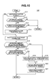
- the flowchart of Fig. 10 shows the operation steps for controlling the reactivation of DPF 12. Also, this routine is repeated every given period.
- step S11 judgment is carried out as to whether the flag of under-reactivation indicates 1 (one) or not. If NO, that is, when the flag indicates 0 (zero) meaning that the reactivation is not under operation, the operation flow goes to step S12. While, if YES, that is, when the flag indicates 1 meaning that the reactivation is under operation, the operation flow goes to step S15 which will be described hereinafter.
- step S12 judgment is carried out as to whether the estimated amount (M) of collected PM provided by the routine of Fig. 9 is equal to or greater than a predetermined first value "M1" or not.
- the predetermined first value "M1” is a threshold value for determining the time when the reactivation of DPF 12 is needed. If NO, that is, when the estimated amount (M) is smaller than the predetermined first value "M1”, the operation flow returns. While, if YES, that is, when the estimated amount (M) is equal to or greater than the predetermined first value "M1", the operation flow goes to step S13.
- step S13 judgment is carried out as to whether the existing operation condition agrees with a reactivation execution condition or not. If NO, that is, when the reactivation execution condition is not established, the operation flow returns. While, if YES, that is, when the reactivation execution condition is established, that is, when the engine 1 rotates at a speed higher than a predetermined level except the time of engine idling and/or at a load higher than a predetermined level or when the associated vehicle moves at a speed higher than a predetermined level, the operation flow goes to step S14 for the purpose of carrying out the reactivation operation.
- step S14 the under-reactivation flag is set to 1 (one), and then the operation flow goes to step S15.
- the under-reactivation flag has been set to 1
- a subsequent flow of the main routine makes step S11 YES, and thus, in such case, the operation flow runs from S11 to S15 directly.
- the reactivation operation is actually carried out in DPF 12. That is, the exhaust gas led to DPF 12 is heated up to heat up DPF 12 for burning and removing PM collected in DPF 12.
- various measures may be used, which are, for example, retardation of fuel injection timing of fuel injection valves 9, post-injection that is an additional fuel injection carried out in an expansion or exhaust stroke of piston, reducing the open degree of intake throttle valve 7, reducing the super-changed pressure generated by variable throat type supercharger 4, etc.,.
- the interior temperature of DPF 12 is increased to a degree that causes burning of the PM collected in DPF 12.
- a target reactivation temperature may be set, and based on this target reactivation temperature, the fuel injection timing, the post-injection amount, the open degree of intake throttle valve 7 or the super-charged pressure may be set.
- step S16 judgment is carried out as to whether the reactivation of DPF 12 has been completely carried out or not. For this judgment, judgment is carried out whether an updated amount (M) of collected PM estimated by the routine of Fig. 9 is smaller than a predetermined second value "M2" or not. It is to be noted that the predetermined second value "M2" is smaller than the above-mentioned predetermined first value "M1". In place of the above-mentioned judgment, another judgment may be used for checking whether the reactivation of DPF 12 has been completely carried out or not. That is, in this judgment, determination is carried out as to whether a predetermined period has passed for the reactivation operation or not.
- step S16 If NO at step S16, that is, when the updated estimated amount (M) of collected PM is greater than the second value "M2" (or the predetermined reactivation time has not passed), the operation flow goes to step S17 judging that the complete reactivation has not been established yet.
- step S17 for judging whether a predetermined reactivation break condition is fulfilled or not, judgment is carried out as to whether the above-mentioned reactivation execution condition fails to be established or not. If NO, that is, when the reactivation execution condition is still established, the operation flow returns to continue the reactivation operation.
- step S16 If YES at step S16, that is, when the updated estimated amount (M) of collected PM is equal to or smaller than the second value "M2" (or the predetermined reactivation time has passed), the operation flow goes to step S18 judging that the complete reactivation has been established.
- the table selection flag is set to 0 (zero) because of establishment of the complete reactivation of DPF 12, and then the operation flow goes to step S20. That is, usage of the first characteristic table of Fig. 8A is determined. It is to be noted that the value of the table selection flag is kept memorized by a back-up RAM of the control unit 13 even after stopping the engine 1.
- step S17 If YES at step S17, that is, when the reactivation execution condition fails to be established, the operation flow goes to step S19 judging that the reactivation should be broken or stopped.
- the table section flag is set to 1 (one) because of failure of establishment of the complete reactivation of DPF 12 (viz., establishment of a partial reactivation of DPF 12), and then the operation flow goes to step S20. That is, usage of the second characteristic table of Fig. 8B is determined.
- step S20 the actual reactivation operation is finished. That is, all parameters that have changed in value at step S15 for the actual reactivation are all returned to their original values.
- the original values are normal values provided in accordance with the operation condition of the engine 1. Then, the operation flow goes to step S21 where the under-reactivation flag is reset to 0 (zero) and the operation flow returns.
- step S1 constitutes a pressure difference detecting means that detects the pressure difference between the upstream and downstream portions of DPF 12
- S5 constitutes a collected PM amount estimating means that estimates the amount of PM collected by DPF 12
- S12 constitutes a reactivation timing judging means that judges a reactivation time when the reactivation of DPF 12 is needed
- S15 constitutes a reactivation carrying out means that actually carries out the reactivation of DPF 12
- S16 to S19 constitute a dispersion condition judging means that judges the dispersion condition of the collected PM in DPF 12
- steps S2 to S4 constitute a correcting means that corrects the estimated amount of collected PM provided by the collected PM amount estimating means.
- the dispersion condition of the collected PM in DPF 12 is judged, and based on this judged dispersion condition, the amount of the collected PM estimated based on the pressure difference at DPF 12 is varied or corrected.
- the estimation accuracy of the collected PM amount is increased or improved irrespective of the dispersion condition of the collected PM. Accordingly, the reactivation action for DPF 12 can be started constantly at the time when the collected PM shows the same amount, and thus, undesired overheating of DPF 12 can be avoided.
- a plurality of different characteristic tables are provided each showing a relationship between a pressure difference at DPF 12 and an estimated amount of collected PM, and the characteristic tables are selectively switched for the estimation of the amount of collected PM in accordance with a dispersion condition of the collected PM in DPF 12. Particularly in case wherein uneven dispersion of the collected PM is severe, a characteristic table is selected which indicates a larger amount of collected PM at the same pressure difference at DPF 12 than that indicated in case wherein even dispersion of the collected PM is made in DPF 12. Thus, the correction of the estimated amount of the collected PM is easily achieved.
- FIG. 11 there is shown a flowchart for use in a second embodiment 200 of the present invention, which is used in place of the flowchart of Fig. 10.
- step S22 If YES at steps S16 and S17, the operation flow goes to step S22. At this step, the actual reactivation operation is finished. Then, at step S23, the under-reactivation flag is reset to 0. Then, the operation flow goes to step S24. At this step S24, an updated pressure difference " ⁇ P" at DPF 12 detected by the routine of Fig. 9 is read and its rate of change "d( ⁇ P)/dt" is calculated, and judgment is carried out as to whether the rate of change "d( ⁇ P)/dt" at the time when the actual reactivation operation has finished is about 0 (zero) or not.
- step S25 judging that the reactivation was a complete reactivation.
- the table selection flag is set to 0 (zero) and the operation flow returns.
- step S24 While, if NO at step S24, that is, when the rate of change "d( ⁇ P)/dt" is not about 0 (zero), the operation flow goes to step S26 judging that the reactivation was a partial reactivation. At this step S26, the table selection flag is set to 1 (one) and the operation flow returns.
- the steps S24 to S26 constitute a dispersion condition judging means a dispersion condition judging means that judges the dispersion condition of the collected PM in DPF 12.
Landscapes
- Engineering & Computer Science (AREA)
- Chemical & Material Sciences (AREA)
- Combustion & Propulsion (AREA)
- Mechanical Engineering (AREA)
- General Engineering & Computer Science (AREA)
- Processes For Solid Components From Exhaust (AREA)
- Electrical Control Of Air Or Fuel Supplied To Internal-Combustion Engine (AREA)
- Combined Controls Of Internal Combustion Engines (AREA)
- Filtering Of Dispersed Particles In Gases (AREA)
Applications Claiming Priority (2)
| Application Number | Priority Date | Filing Date | Title |
|---|---|---|---|
| JP2003004967 | 2003-01-10 | ||
| JP2003004967A JP3864910B2 (ja) | 2003-01-10 | 2003-01-10 | 内燃機関の排気浄化装置 |
Publications (2)
| Publication Number | Publication Date |
|---|---|
| EP1437486A1 true EP1437486A1 (fr) | 2004-07-14 |
| EP1437486B1 EP1437486B1 (fr) | 2006-03-15 |
Family
ID=32501260
Family Applications (1)
| Application Number | Title | Priority Date | Filing Date |
|---|---|---|---|
| EP04000175A Expired - Fee Related EP1437486B1 (fr) | 2003-01-10 | 2004-01-07 | Système de purification des gaz d'échappement d'un moteur à combustion interne |
Country Status (5)
| Country | Link |
|---|---|
| US (1) | US7153342B2 (fr) |
| EP (1) | EP1437486B1 (fr) |
| JP (1) | JP3864910B2 (fr) |
| CN (1) | CN1296605C (fr) |
| DE (1) | DE602004000466T2 (fr) |
Cited By (7)
| Publication number | Priority date | Publication date | Assignee | Title |
|---|---|---|---|---|
| FR2874968A1 (fr) * | 2004-09-06 | 2006-03-10 | Renault Sas | Procede de commande d'une pression de suralimentation dans un moteur de vehicule |
| WO2006056718A1 (fr) * | 2004-11-29 | 2006-06-01 | Renault S.A.S. | Procede et dispositif d'arret d'une phase de regeneration de filtre a particules de moteur diesel de vehicule automobile |
| EP1722082A3 (fr) * | 2005-05-13 | 2007-01-03 | HONDA MOTOR CO., Ltd. | Système de régulation des émissions d'un moteur à combustion interne et son procédé de commande |
| EP1849972A1 (fr) * | 2006-04-27 | 2007-10-31 | HONDA MOTOR CO., Ltd. | Appareil pour détecter l'état d'un filtre à particules |
| FR2914691A1 (fr) * | 2007-04-06 | 2008-10-10 | Renault Sas | Procede et dispositif de generation de signal d'arret de regeneration de filtre a particules |
| EP2148071A1 (fr) * | 2008-07-23 | 2010-01-27 | Mazda Motor Corporation | Système de régénération de filtre à particules |
| WO2015133092A1 (fr) * | 2014-03-07 | 2015-09-11 | Toyota Jidosha Kabushiki Kaisha | Appareil de purification de gaz d'échappement pour moteur à combustion interne |
Families Citing this family (34)
| Publication number | Priority date | Publication date | Assignee | Title |
|---|---|---|---|---|
| US20050155345A1 (en) * | 2002-03-29 | 2005-07-21 | Tokyo Electron Limited | Device and method for purifying exhaust gas from industrial vehicle engine |
| WO2005070175A2 (fr) * | 2004-01-13 | 2005-08-04 | Arvin Technologies, Inc. | Ensemble de reduction d'emission et son procede de fonctionnement |
| JP4403944B2 (ja) * | 2004-01-13 | 2010-01-27 | 株式会社デンソー | 内燃機関の排気浄化装置 |
| US7434388B2 (en) * | 2004-12-22 | 2008-10-14 | Detroit Diesel Corporation | Method and system for regeneration of a particulate filter |
| US7374600B2 (en) * | 2005-01-28 | 2008-05-20 | Detroit Diesel Corporation | System and method for excluding false back pressure faults after installation of a particulate trap filter |
| JP4531641B2 (ja) * | 2005-06-23 | 2010-08-25 | 本田技研工業株式会社 | 不整地走行車両のエアクリーナ |
| DE102005029338A1 (de) * | 2005-06-24 | 2007-02-08 | Emitec Gesellschaft Für Emissionstechnologie Mbh | Verfahren zum Betrieb einer Partikelfalle sowie Vorrichtung zur Durchführung des Verfahrens |
| FR2890926A1 (fr) * | 2005-09-21 | 2007-03-23 | Renault Sas | Procede d'obtention de gaz d'echappement charges en carburant |
| US7758676B2 (en) | 2006-10-03 | 2010-07-20 | Gm Global Technology Operations, Inc. | Adaptive learning method for clean particulate filter pressure drop |
| JP4645851B2 (ja) * | 2006-11-20 | 2011-03-09 | 三菱自動車工業株式会社 | 内燃機関の排気浄化装置 |
| DE102006055237A1 (de) * | 2006-11-23 | 2008-05-29 | Robert Bosch Gmbh | Verfahren zur Prüfung der Vollständigkeit einer Regeneration eines Partikelfilters im Abgas eines Verbrennungsmotors |
| JP4100448B1 (ja) * | 2007-01-26 | 2008-06-11 | いすゞ自動車株式会社 | 排気ガス浄化方法及び排気ガス浄化システム |
| JP4935390B2 (ja) * | 2007-02-05 | 2012-05-23 | トヨタ自動車株式会社 | 内燃機関の排気浄化システム |
| US7861515B2 (en) * | 2007-07-13 | 2011-01-04 | Ford Global Technologies, Llc | Monitoring of exhaust gas oxygen sensor performance |
| US8011180B2 (en) | 2007-08-16 | 2011-09-06 | Ford Global Technologies, Llc | Particulate filter regeneration |
| JP5123686B2 (ja) * | 2008-02-08 | 2013-01-23 | 三菱重工業株式会社 | Dpf堆積量推定装置 |
| EP2177258B1 (fr) * | 2008-10-17 | 2016-04-20 | Mazda Motor Corporation | Catalyseur de purification des gaz d'échappement |
| US9371754B2 (en) * | 2009-03-12 | 2016-06-21 | Caterpillar Inc. | Diesel particulate filter regeneration control and method |
| JP5307056B2 (ja) * | 2010-03-05 | 2013-10-02 | ヤンマー株式会社 | エンジン装置 |
| JP5382210B2 (ja) * | 2010-04-30 | 2014-01-08 | トヨタ自動車株式会社 | パティキュレートフィルタの故障検出装置及び故障検出方法 |
| US8478565B2 (en) * | 2010-07-02 | 2013-07-02 | GM Global Technology Operations LLC | Method of monitoring soot mass in a particulate filter and monitoring system for same with correction for active regeneration inefficiency |
| US8365586B2 (en) * | 2010-07-02 | 2013-02-05 | GM Global Technology Operations LLC | Method of monitoring soot mass in a particulate filter and monitoring system for same |
| JP5338996B2 (ja) * | 2010-12-07 | 2013-11-13 | トヨタ自動車株式会社 | 内燃機関の粒子状物質検出装置 |
| US8523988B2 (en) * | 2011-01-11 | 2013-09-03 | GM Global Technology Operations LLC | System and method for estimating a mass of particulate matter accumulated in a particulate filter |
| US8484955B2 (en) * | 2011-02-04 | 2013-07-16 | GM Global Technology Operations LLC | System and method for estimating an amount of particulate matter accumulated in a particulate filter |
| JP5520359B2 (ja) | 2011-11-10 | 2014-06-11 | 株式会社堀場製作所 | 排ガス分析システム及び当該システム用プログラム |
| US8935953B2 (en) * | 2013-05-15 | 2015-01-20 | GM Global Technology Operations LLC | Adaptive soot mass estimation in a vehicle exhaust after-treatment device |
| US9726058B2 (en) * | 2015-01-08 | 2017-08-08 | Ford Global Technologies, Llc | Idle speed GPF regeneration |
| JP6256393B2 (ja) * | 2015-03-17 | 2018-01-10 | トヨタ自動車株式会社 | 内燃機関の排気浄化システム |
| CN104806365A (zh) * | 2015-03-31 | 2015-07-29 | 凯龙高科技股份有限公司 | Dpf柴油机颗粒过滤系统进气节流再生温度控制方法 |
| JP6233450B2 (ja) * | 2015-06-02 | 2017-11-22 | トヨタ自動車株式会社 | 排気浄化システムの制御装置 |
| US10760464B2 (en) * | 2017-08-07 | 2020-09-01 | GM Global Technology Operations LLC | Methods for monitoring and regenerating selective catalytic reduction filter devices |
| CN114135052A (zh) * | 2021-12-08 | 2022-03-04 | 深圳市凯丰建筑设计有限公司 | 一种具有空气调节功能的预制建筑隔板及其调节方法 |
| CN114307438B (zh) * | 2022-01-10 | 2023-04-11 | 浙江大学 | 基于荷电强化过滤的船舶尾气黑碳深度脱除系统及方法 |
Citations (6)
| Publication number | Priority date | Publication date | Assignee | Title |
|---|---|---|---|---|
| JPS63295815A (ja) * | 1987-05-28 | 1988-12-02 | Isuzu Motors Ltd | パティキュレ−トトラップの再生装置 |
| EP0402705A1 (fr) * | 1989-06-16 | 1990-12-19 | Isuzu Motors Limited | Système de régénération pour filtre à particules |
| JPH07310524A (ja) * | 1994-05-13 | 1995-11-28 | Nippondenso Co Ltd | ディーゼルパティキュレート捕集量検出装置 |
| JPH11153020A (ja) * | 1997-11-20 | 1999-06-08 | Nissan Motor Co Ltd | エンジンの排気微粒子処理装置 |
| US20010010152A1 (en) * | 2000-01-20 | 2001-08-02 | Peugeot Citroen Automobiles S.A. | System for assisting the regeneration of a particle filter integrated into an exhaust line of a motor vehicle diesel engine |
| EP1229223A1 (fr) * | 2001-02-05 | 2002-08-07 | Nissan Motor Co., Ltd. | Dispositif d'épuration de gas d'échappement pour un moteur à combustion |
Family Cites Families (12)
| Publication number | Priority date | Publication date | Assignee | Title |
|---|---|---|---|---|
| GB2239407B (en) * | 1989-12-27 | 1994-10-12 | Nissan Motor | Exhaust gas purifying device for an internal combustion engine |
| JP2616075B2 (ja) | 1989-12-27 | 1997-06-04 | 日産自動車株式会社 | エンジンの排気浄化装置 |
| JP3021921B2 (ja) | 1992-02-21 | 2000-03-15 | 株式会社日本自動車部品総合研究所 | 排気微粒子浄化装置 |
| JPH05240026A (ja) | 1992-02-28 | 1993-09-17 | Tonen Corp | ディーゼルエンジンの排気ガス浄化装置 |
| JPH05313022A (ja) | 1992-05-06 | 1993-11-26 | Nippon Telegr & Teleph Corp <Ntt> | 光心線収容ケーブルの識別方法 |
| JPH0734853A (ja) | 1993-07-26 | 1995-02-03 | Nippondenso Co Ltd | ディーゼルエンジンの排気浄化装置 |
| EP1103702B1 (fr) * | 1999-11-26 | 2003-05-14 | Renault s.a.s. | Procédé de gestion du fonctionnement d'un filtre à particules et d'un moteur à combustion interne |
| US6405528B1 (en) * | 2000-11-20 | 2002-06-18 | Ford Global Technologies, Inc. | Method for determining load on particulate filter for engine exhaust, including estimation of ash content |
| US6622480B2 (en) * | 2001-02-21 | 2003-09-23 | Isuzu Motors Limited | Diesel particulate filter unit and regeneration control method of the same |
| JP4022723B2 (ja) * | 2002-01-11 | 2007-12-19 | 株式会社デンソー | 排気フィルタ再生装置及び方法 |
| ITTO20020072A1 (it) * | 2002-01-25 | 2003-07-25 | Fiat Ricerche | Metodo per la determinazione della quantita' di particolato accumulata in un filtro per particolato. |
| JP3801135B2 (ja) * | 2003-01-08 | 2006-07-26 | 日産自動車株式会社 | エンジンの排気ガス浄化装置 |
-
2003
- 2003-01-10 JP JP2003004967A patent/JP3864910B2/ja not_active Expired - Fee Related
-
2004
- 2004-01-07 EP EP04000175A patent/EP1437486B1/fr not_active Expired - Fee Related
- 2004-01-07 DE DE602004000466T patent/DE602004000466T2/de not_active Expired - Lifetime
- 2004-01-08 US US10/752,519 patent/US7153342B2/en not_active Expired - Fee Related
- 2004-01-09 CN CNB2004100020586A patent/CN1296605C/zh not_active Expired - Fee Related
Patent Citations (6)
| Publication number | Priority date | Publication date | Assignee | Title |
|---|---|---|---|---|
| JPS63295815A (ja) * | 1987-05-28 | 1988-12-02 | Isuzu Motors Ltd | パティキュレ−トトラップの再生装置 |
| EP0402705A1 (fr) * | 1989-06-16 | 1990-12-19 | Isuzu Motors Limited | Système de régénération pour filtre à particules |
| JPH07310524A (ja) * | 1994-05-13 | 1995-11-28 | Nippondenso Co Ltd | ディーゼルパティキュレート捕集量検出装置 |
| JPH11153020A (ja) * | 1997-11-20 | 1999-06-08 | Nissan Motor Co Ltd | エンジンの排気微粒子処理装置 |
| US20010010152A1 (en) * | 2000-01-20 | 2001-08-02 | Peugeot Citroen Automobiles S.A. | System for assisting the regeneration of a particle filter integrated into an exhaust line of a motor vehicle diesel engine |
| EP1229223A1 (fr) * | 2001-02-05 | 2002-08-07 | Nissan Motor Co., Ltd. | Dispositif d'épuration de gas d'échappement pour un moteur à combustion |
Non-Patent Citations (3)
| Title |
|---|
| PATENT ABSTRACTS OF JAPAN vol. 013, no. 122 (M - 807) 27 March 1989 (1989-03-27) * |
| PATENT ABSTRACTS OF JAPAN vol. 1996, no. 03 29 March 1996 (1996-03-29) * |
| PATENT ABSTRACTS OF JAPAN vol. 1999, no. 11 30 September 1999 (1999-09-30) * |
Cited By (11)
| Publication number | Priority date | Publication date | Assignee | Title |
|---|---|---|---|---|
| FR2874968A1 (fr) * | 2004-09-06 | 2006-03-10 | Renault Sas | Procede de commande d'une pression de suralimentation dans un moteur de vehicule |
| WO2006056718A1 (fr) * | 2004-11-29 | 2006-06-01 | Renault S.A.S. | Procede et dispositif d'arret d'une phase de regeneration de filtre a particules de moteur diesel de vehicule automobile |
| FR2878566A1 (fr) * | 2004-11-29 | 2006-06-02 | Renault Sas | Procede et dispositif d'arret d'une phase de regeneration de filtre a particules de moteur diesel de vehicule automobile |
| EP1722082A3 (fr) * | 2005-05-13 | 2007-01-03 | HONDA MOTOR CO., Ltd. | Système de régulation des émissions d'un moteur à combustion interne et son procédé de commande |
| EP1865165A1 (fr) * | 2005-05-13 | 2007-12-12 | HONDA MOTOR CO., Ltd. | Système de contrôle d'émissions d'échappement et procédé pour moteur à combustion interne |
| EP1849972A1 (fr) * | 2006-04-27 | 2007-10-31 | HONDA MOTOR CO., Ltd. | Appareil pour détecter l'état d'un filtre à particules |
| FR2914691A1 (fr) * | 2007-04-06 | 2008-10-10 | Renault Sas | Procede et dispositif de generation de signal d'arret de regeneration de filtre a particules |
| EP2148071A1 (fr) * | 2008-07-23 | 2010-01-27 | Mazda Motor Corporation | Système de régénération de filtre à particules |
| US8051646B2 (en) | 2008-07-23 | 2011-11-08 | Mazda Motor Corporation | Particulate filter regenerating system |
| WO2015133092A1 (fr) * | 2014-03-07 | 2015-09-11 | Toyota Jidosha Kabushiki Kaisha | Appareil de purification de gaz d'échappement pour moteur à combustion interne |
| CN106103924A (zh) * | 2014-03-07 | 2016-11-09 | 丰田自动车株式会社 | 用于内燃机的排气净化装置 |
Also Published As
| Publication number | Publication date |
|---|---|
| US7153342B2 (en) | 2006-12-26 |
| EP1437486B1 (fr) | 2006-03-15 |
| CN1517522A (zh) | 2004-08-04 |
| DE602004000466T2 (de) | 2006-08-24 |
| CN1296605C (zh) | 2007-01-24 |
| US20040139852A1 (en) | 2004-07-22 |
| JP2004218486A (ja) | 2004-08-05 |
| DE602004000466D1 (de) | 2006-05-11 |
| JP3864910B2 (ja) | 2007-01-10 |
Similar Documents
| Publication | Publication Date | Title |
|---|---|---|
| US7153342B2 (en) | Exhaust gas purifying system of internal combustion engine | |
| EP1431531B1 (fr) | Dispositif de régénération d'un filtre à particules | |
| EP1229223B1 (fr) | Dispositif d'épuration de gas d'échappement pour un moteur à combustion interne | |
| EP1435443B1 (fr) | Dispositif pour la purification de gaz d'echappement d'un moteur à combustion interne | |
| US7146804B2 (en) | Exhaust gas cleaning system having particulate filter | |
| US7607295B2 (en) | Particulate accumulation amount estimating system | |
| JP3969196B2 (ja) | 内燃機関の燃料噴射制御装置 | |
| EP1437497B1 (fr) | Dispositif et méthode de régénération d'un filtre à particules applicable à le dispositif de purification des gaz d'échappement d'un moteur à combustion interne | |
| EP1431530B1 (fr) | Dispositif de régénération d'un filtre à particules | |
| US7134275B2 (en) | Regeneration control of diesel particulate filter | |
| EP1455060B1 (fr) | Dispositif de purification des gaz d'échappement d'un moteur | |
| EP1568865A1 (fr) | Régénération d'un filtre à particules diesel | |
| JP4032849B2 (ja) | 車両用エンジンの排気浄化装置 | |
| EP1477652A2 (fr) | Système de contrôle des émissions d'un moteur à combustion interne | |
| US7007463B2 (en) | Engine fuel injection control system | |
| US20050126162A1 (en) | Regeneration of diesel particulate filter | |
| JP2000170521A (ja) | パティキュレートフィルタの捕集量算出方法及び再生方法 | |
| JP3454351B2 (ja) | パティキュレートフィルタの再生処理制御装置 | |
| JP2000161044A (ja) | パティキュレートフィルタの再生制御装置 | |
| JP2004197722A (ja) | パティキュレートフィルタの再生装置及びエンジンの排気ガス浄化装置 | |
| JP4103665B2 (ja) | 排気浄化装置 | |
| JP7230835B2 (ja) | 内燃機関の制御装置 | |
| JP4103748B2 (ja) | 内燃機関の排気浄化装置 | |
| JP2023102013A (ja) | 排気浄化装置 | |
| JP4103429B2 (ja) | 排気ガス浄化装置 |
Legal Events
| Date | Code | Title | Description |
|---|---|---|---|
| PUAI | Public reference made under article 153(3) epc to a published international application that has entered the european phase |
Free format text: ORIGINAL CODE: 0009012 |
|
| 17P | Request for examination filed |
Effective date: 20040107 |
|
| AK | Designated contracting states |
Kind code of ref document: A1 Designated state(s): AT BE BG CH CY CZ DE DK EE ES FI FR GB GR HU IE IT LI LU MC NL PT RO SE SI SK TR |
|
| AX | Request for extension of the european patent |
Extension state: AL LT LV MK |
|
| 17Q | First examination report despatched |
Effective date: 20050111 |
|
| AKX | Designation fees paid |
Designated state(s): DE FR GB |
|
| GRAP | Despatch of communication of intention to grant a patent |
Free format text: ORIGINAL CODE: EPIDOSNIGR1 |
|
| GRAS | Grant fee paid |
Free format text: ORIGINAL CODE: EPIDOSNIGR3 |
|
| GRAA | (expected) grant |
Free format text: ORIGINAL CODE: 0009210 |
|
| AK | Designated contracting states |
Kind code of ref document: B1 Designated state(s): DE FR GB |
|
| REG | Reference to a national code |
Ref country code: GB Ref legal event code: FG4D |
|
| REF | Corresponds to: |
Ref document number: 602004000466 Country of ref document: DE Date of ref document: 20060511 Kind code of ref document: P |
|
| ET | Fr: translation filed | ||
| PLBE | No opposition filed within time limit |
Free format text: ORIGINAL CODE: 0009261 |
|
| STAA | Information on the status of an ep patent application or granted ep patent |
Free format text: STATUS: NO OPPOSITION FILED WITHIN TIME LIMIT |
|
| 26N | No opposition filed |
Effective date: 20061218 |
|
| PGFP | Annual fee paid to national office [announced via postgrant information from national office to epo] |
Ref country code: FR Payment date: 20100208 Year of fee payment: 7 |
|
| PGFP | Annual fee paid to national office [announced via postgrant information from national office to epo] |
Ref country code: DE Payment date: 20091231 Year of fee payment: 7 Ref country code: GB Payment date: 20100106 Year of fee payment: 7 |
|
| GBPC | Gb: european patent ceased through non-payment of renewal fee |
Effective date: 20110107 |
|
| REG | Reference to a national code |
Ref country code: FR Ref legal event code: ST Effective date: 20110930 |
|
| PG25 | Lapsed in a contracting state [announced via postgrant information from national office to epo] |
Ref country code: FR Free format text: LAPSE BECAUSE OF NON-PAYMENT OF DUE FEES Effective date: 20110131 |
|
| PG25 | Lapsed in a contracting state [announced via postgrant information from national office to epo] |
Ref country code: GB Free format text: LAPSE BECAUSE OF NON-PAYMENT OF DUE FEES Effective date: 20110107 |
|
| REG | Reference to a national code |
Ref country code: DE Ref legal event code: R119 Ref document number: 602004000466 Country of ref document: DE Effective date: 20110802 |
|
| PG25 | Lapsed in a contracting state [announced via postgrant information from national office to epo] |
Ref country code: DE Free format text: LAPSE BECAUSE OF NON-PAYMENT OF DUE FEES Effective date: 20110802 |