EP1437476A2 - Entraínement pour un panneau, en particulier un panneau de porte ou de fenêtre - Google Patents
Entraínement pour un panneau, en particulier un panneau de porte ou de fenêtre Download PDFInfo
- Publication number
- EP1437476A2 EP1437476A2 EP03029536A EP03029536A EP1437476A2 EP 1437476 A2 EP1437476 A2 EP 1437476A2 EP 03029536 A EP03029536 A EP 03029536A EP 03029536 A EP03029536 A EP 03029536A EP 1437476 A2 EP1437476 A2 EP 1437476A2
- Authority
- EP
- European Patent Office
- Prior art keywords
- opening
- flat belt
- drive according
- spring
- drive
- Prior art date
- Legal status (The legal status is an assumption and is not a legal conclusion. Google has not performed a legal analysis and makes no representation as to the accuracy of the status listed.)
- Granted
Links
- 230000009471 action Effects 0.000 claims abstract description 5
- 230000005540 biological transmission Effects 0.000 claims description 11
- 230000000295 complement effect Effects 0.000 claims description 2
- 230000033001 locomotion Effects 0.000 description 8
- 239000000463 material Substances 0.000 description 4
- 238000012423 maintenance Methods 0.000 description 3
- 238000000034 method Methods 0.000 description 3
- 230000036316 preload Effects 0.000 description 3
- 230000008569 process Effects 0.000 description 3
- 230000000694 effects Effects 0.000 description 2
- 230000002040 relaxant effect Effects 0.000 description 2
- 238000004804 winding Methods 0.000 description 2
- 239000004677 Nylon Substances 0.000 description 1
- 229910000831 Steel Inorganic materials 0.000 description 1
- 238000005452 bending Methods 0.000 description 1
- 230000008901 benefit Effects 0.000 description 1
- 230000008859 change Effects 0.000 description 1
- 239000011248 coating agent Substances 0.000 description 1
- 238000000576 coating method Methods 0.000 description 1
- 230000006835 compression Effects 0.000 description 1
- 238000007906 compression Methods 0.000 description 1
- 230000008878 coupling Effects 0.000 description 1
- 238000010168 coupling process Methods 0.000 description 1
- 238000005859 coupling reaction Methods 0.000 description 1
- 230000001419 dependent effect Effects 0.000 description 1
- 238000006073 displacement reaction Methods 0.000 description 1
- 229920001971 elastomer Polymers 0.000 description 1
- 239000003365 glass fiber Substances 0.000 description 1
- 238000009434 installation Methods 0.000 description 1
- 238000005461 lubrication Methods 0.000 description 1
- 229920001778 nylon Polymers 0.000 description 1
- 239000004033 plastic Substances 0.000 description 1
- 229920003023 plastic Polymers 0.000 description 1
- 229920002635 polyurethane Polymers 0.000 description 1
- 239000004814 polyurethane Substances 0.000 description 1
- 239000010959 steel Substances 0.000 description 1
Images


Classifications
-
- E—FIXED CONSTRUCTIONS
- E05—LOCKS; KEYS; WINDOW OR DOOR FITTINGS; SAFES
- E05F—DEVICES FOR MOVING WINGS INTO OPEN OR CLOSED POSITION; CHECKS FOR WINGS; WING FITTINGS NOT OTHERWISE PROVIDED FOR, CONCERNED WITH THE FUNCTIONING OF THE WING
- E05F1/00—Closers or openers for wings, not otherwise provided for in this subclass
- E05F1/08—Closers or openers for wings, not otherwise provided for in this subclass spring-actuated, e.g. for horizontally sliding wings
- E05F1/10—Closers or openers for wings, not otherwise provided for in this subclass spring-actuated, e.g. for horizontally sliding wings for swinging wings, e.g. counterbalance
- E05F1/1041—Closers or openers for wings, not otherwise provided for in this subclass spring-actuated, e.g. for horizontally sliding wings for swinging wings, e.g. counterbalance with a coil spring perpendicular to the pivot axis
- E05F1/105—Closers or openers for wings, not otherwise provided for in this subclass spring-actuated, e.g. for horizontally sliding wings for swinging wings, e.g. counterbalance with a coil spring perpendicular to the pivot axis with a compression spring
-
- E—FIXED CONSTRUCTIONS
- E05—LOCKS; KEYS; WINDOW OR DOOR FITTINGS; SAFES
- E05F—DEVICES FOR MOVING WINGS INTO OPEN OR CLOSED POSITION; CHECKS FOR WINGS; WING FITTINGS NOT OTHERWISE PROVIDED FOR, CONCERNED WITH THE FUNCTIONING OF THE WING
- E05F15/00—Power-operated mechanisms for wings
- E05F15/60—Power-operated mechanisms for wings using electrical actuators
- E05F15/603—Power-operated mechanisms for wings using electrical actuators using rotary electromotors
- E05F15/611—Power-operated mechanisms for wings using electrical actuators using rotary electromotors for swinging wings
- E05F15/63—Power-operated mechanisms for wings using electrical actuators using rotary electromotors for swinging wings operated by swinging arms
-
- E—FIXED CONSTRUCTIONS
- E05—LOCKS; KEYS; WINDOW OR DOOR FITTINGS; SAFES
- E05F—DEVICES FOR MOVING WINGS INTO OPEN OR CLOSED POSITION; CHECKS FOR WINGS; WING FITTINGS NOT OTHERWISE PROVIDED FOR, CONCERNED WITH THE FUNCTIONING OF THE WING
- E05F15/00—Power-operated mechanisms for wings
- E05F15/70—Power-operated mechanisms for wings with automatic actuation
- E05F15/72—Power-operated mechanisms for wings with automatic actuation responsive to emergency conditions, e.g. fire
-
- E—FIXED CONSTRUCTIONS
- E05—LOCKS; KEYS; WINDOW OR DOOR FITTINGS; SAFES
- E05F—DEVICES FOR MOVING WINGS INTO OPEN OR CLOSED POSITION; CHECKS FOR WINGS; WING FITTINGS NOT OTHERWISE PROVIDED FOR, CONCERNED WITH THE FUNCTIONING OF THE WING
- E05F15/00—Power-operated mechanisms for wings
- E05F15/60—Power-operated mechanisms for wings using electrical actuators
- E05F15/603—Power-operated mechanisms for wings using electrical actuators using rotary electromotors
- E05F15/611—Power-operated mechanisms for wings using electrical actuators using rotary electromotors for swinging wings
- E05F15/627—Power-operated mechanisms for wings using electrical actuators using rotary electromotors for swinging wings operated by flexible elongated pulling elements, e.g. belts, chains or cables
-
- E—FIXED CONSTRUCTIONS
- E05—LOCKS; KEYS; WINDOW OR DOOR FITTINGS; SAFES
- E05Y—INDEXING SCHEME ASSOCIATED WITH SUBCLASSES E05D AND E05F, RELATING TO CONSTRUCTION ELEMENTS, ELECTRIC CONTROL, POWER SUPPLY, POWER SIGNAL OR TRANSMISSION, USER INTERFACES, MOUNTING OR COUPLING, DETAILS, ACCESSORIES, AUXILIARY OPERATIONS NOT OTHERWISE PROVIDED FOR, APPLICATION THEREOF
- E05Y2201/00—Constructional elements; Accessories therefor
- E05Y2201/40—Motors; Magnets; Springs; Weights; Accessories therefor
- E05Y2201/404—Function thereof
- E05Y2201/41—Function thereof for closing
-
- E—FIXED CONSTRUCTIONS
- E05—LOCKS; KEYS; WINDOW OR DOOR FITTINGS; SAFES
- E05Y—INDEXING SCHEME ASSOCIATED WITH SUBCLASSES E05D AND E05F, RELATING TO CONSTRUCTION ELEMENTS, ELECTRIC CONTROL, POWER SUPPLY, POWER SIGNAL OR TRANSMISSION, USER INTERFACES, MOUNTING OR COUPLING, DETAILS, ACCESSORIES, AUXILIARY OPERATIONS NOT OTHERWISE PROVIDED FOR, APPLICATION THEREOF
- E05Y2400/00—Electronic control; Electrical power; Power supply; Power or signal transmission; User interfaces
- E05Y2400/10—Electronic control
- E05Y2400/30—Electronic control of motors
- E05Y2400/302—Electronic control of motors during electric motor braking
-
- E—FIXED CONSTRUCTIONS
- E05—LOCKS; KEYS; WINDOW OR DOOR FITTINGS; SAFES
- E05Y—INDEXING SCHEME ASSOCIATED WITH SUBCLASSES E05D AND E05F, RELATING TO CONSTRUCTION ELEMENTS, ELECTRIC CONTROL, POWER SUPPLY, POWER SIGNAL OR TRANSMISSION, USER INTERFACES, MOUNTING OR COUPLING, DETAILS, ACCESSORIES, AUXILIARY OPERATIONS NOT OTHERWISE PROVIDED FOR, APPLICATION THEREOF
- E05Y2400/00—Electronic control; Electrical power; Power supply; Power or signal transmission; User interfaces
- E05Y2400/10—Electronic control
- E05Y2400/36—Speed control, detection or monitoring
-
- E—FIXED CONSTRUCTIONS
- E05—LOCKS; KEYS; WINDOW OR DOOR FITTINGS; SAFES
- E05Y—INDEXING SCHEME ASSOCIATED WITH SUBCLASSES E05D AND E05F, RELATING TO CONSTRUCTION ELEMENTS, ELECTRIC CONTROL, POWER SUPPLY, POWER SIGNAL OR TRANSMISSION, USER INTERFACES, MOUNTING OR COUPLING, DETAILS, ACCESSORIES, AUXILIARY OPERATIONS NOT OTHERWISE PROVIDED FOR, APPLICATION THEREOF
- E05Y2800/00—Details, accessories and auxiliary operations not otherwise provided for
- E05Y2800/40—Physical or chemical protection
- E05Y2800/414—Physical or chemical protection against high or low temperatures
- E05Y2800/416—Physical or chemical protection against high or low temperatures against fire
-
- E—FIXED CONSTRUCTIONS
- E05—LOCKS; KEYS; WINDOW OR DOOR FITTINGS; SAFES
- E05Y—INDEXING SCHEME ASSOCIATED WITH SUBCLASSES E05D AND E05F, RELATING TO CONSTRUCTION ELEMENTS, ELECTRIC CONTROL, POWER SUPPLY, POWER SIGNAL OR TRANSMISSION, USER INTERFACES, MOUNTING OR COUPLING, DETAILS, ACCESSORIES, AUXILIARY OPERATIONS NOT OTHERWISE PROVIDED FOR, APPLICATION THEREOF
- E05Y2900/00—Application of doors, windows, wings or fittings thereof
- E05Y2900/10—Application of doors, windows, wings or fittings thereof for buildings or parts thereof
- E05Y2900/13—Type of wing
- E05Y2900/132—Doors
-
- E—FIXED CONSTRUCTIONS
- E05—LOCKS; KEYS; WINDOW OR DOOR FITTINGS; SAFES
- E05Y—INDEXING SCHEME ASSOCIATED WITH SUBCLASSES E05D AND E05F, RELATING TO CONSTRUCTION ELEMENTS, ELECTRIC CONTROL, POWER SUPPLY, POWER SIGNAL OR TRANSMISSION, USER INTERFACES, MOUNTING OR COUPLING, DETAILS, ACCESSORIES, AUXILIARY OPERATIONS NOT OTHERWISE PROVIDED FOR, APPLICATION THEREOF
- E05Y2900/00—Application of doors, windows, wings or fittings thereof
- E05Y2900/10—Application of doors, windows, wings or fittings thereof for buildings or parts thereof
- E05Y2900/13—Type of wing
- E05Y2900/148—Windows
Definitions
- the invention relates to a drive according to the preamble of claim 1.
- a drive for a wing in particular a door or a window, with an electric drive motor with which the wing at least in the opening direction is driven via an output shaft, known.
- the drive has a closer spring with which the wing in the closing direction via the output shaft is drivable. The sash is opened under the action of the drive motor.
- the closer spring is preloaded. Closing the wing takes place under the action of the closer spring.
- a flexible power transmission element is used for power transmission between the drive motor and the closer spring.
- the closer spring is supported with one end on one in the housing arranged stop and with its other end at one in the housing slidably guided spring plate.
- the power transmission element is with his one end arranged on a cam disc circumferentially and fixed with its other end to the spring plate.
- the power transmission element is designed as a Bowden cable or as a chain.
- a disadvantage of using a Bowden cable is that it is connected subjected to a large bend with a cam disc with a relatively small radius becomes. This leads to wear on the Bowden cable, due to this can tear under certain circumstances.
- the use of a cam is great Diameter required, resulting in a large depth of the drive housing leads.
- the Bowden cable can also move under heavy tensile loads length, which may require complex readjustments to maintain proper functionality of the drive is required.
- a chain is more wear-resistant than a Bowden cable, but it is voluminous, so that they have a relatively large installation space in the housing of the drive needed.
- the chain is also attached to the cam disc and spring retainer complex, and when winding the chain on the cam disc results in several superimposed chain layers a large overall diameter of cam and chain layers, which in turn is a drive housing with large Depth requires.
- the invention has for its object to a generic drive create, its flexible power transmission element low maintenance and wear is suitable for cams with a small radius and also one has a small footprint.
- the power transmission element is designed as a flat belt. With flat belt small bending radii can be realized, which means that they can also be used in conjunction with cams small diameter can be used. This is more compact to achieve Dimensions of the drive essential, because the diameter of the cam is decisive for the depth of the drive housing. Because of that flat belt do not require lubrication and are dimensioned as intended the drive requires very little maintenance. On Another advantage when using a flat belt in the generic drive is that this is in contrast even with strong tensile stress to a Bowden cable, barely long. This also leads to a low maintenance Drive.
- the outer material of the flat belt can be made of polyurethane or rubber be formed, but also the use of other suitable materials like plastic, especially nylon is conceivable. It is essential that that Material is flexible and low wear.
- Ropes can be inserted into the outer material to increase the stability of the flat belt with high tensile strength, especially steel cable or glass fiber strands, embedded his.
- the drive is easy to install by installing a cam
- the flat belt is then fixed to the cam disk by friction, with further fastening elements, e.g. screws can be dispensed with. In particular caused by the closer spring Tension increases this friction.
- the flat belt can be attached to the cam by an additional fastening device, for example, a clamping screw.
- the spring plate-side assembly of the flat belt is also easy by the spring plate a sleeve with an opening for receiving the other end of the belt of the flat belt, the attachment of the flat belt on Spring plate can be designed such that the flat belt by at least a jaw can be fixed in the opening of the sleeve.
- a particularly secure mounting of the flat belt on the spring plate side can thereby achieved that the belt end is passed through the opening of the sleeve is the end of the belt forming a loop around a bolt led around and in the opposite direction into the opening of the sleeve is introduced.
- the clamping jaw is complementary.
- the jaw in the opening of the sleeve can additionally by a additional fastening device, for example a clamping screw, can be fixed his.
- a additional fastening device for example a clamping screw
- the drive motor can be directly or via an electronic control device can be controlled. This involves transmitting the position and the speed of rotation the output shaft to the control device required. This can be done using a rotation angle sensor.
- the rotation angle sensor can have one or more switches and one interact on the output shaft rotatably arranged contactor. Alternatively, the rotation angle sensor can be located elsewhere on the drive, for example arranged on the shaft of the drive motor or a gear element his.
- the use of a linear displacement sensor is also conceivable which is the position of a linearly movable drive element, for example of the spring plate.
- a particular wing position dependent Setpoint profile for the opening and closing speed of the drive connected wing can be saved.
- the signal from the rotation angle sensor is compared with the respective values of the setpoint profile and the drive motor controlled accordingly.
- the closing of the wing takes place with effect the closer spring.
- the drive motor is operated as a generator and thus slows down the closing process.
- Braking can be done by direct Connection of the drive motor to a constant braking resistor respectively. If necessary, the braking shortly before reaching the Closed position of the door wing can be lifted to a so-called Realize "final blow". This can be done using a switch that is just before Reaching the closed position of the door leaf is pressed and the Brake circuit breaks.
- a "comfortable” braking can be done via the Control device take place by the braking resistor depending on Wing position and speed can be varied.
- the setpoint profile that can be stored in the control device can be changed during commissioning of the drive can be determined as part of a so-called "learning drive”.
- the drive motor can do this with a predetermined power in opening and Closing direction are operated. So are those necessary for the operation of the drive Parameters such as opening width and weight (moment of inertia) of the wing determined.
- the set preload of the closer spring is also possible this parameterization process can be determined and via a suitable display device displayable. In comparison to the determined sash weight, for example, also by means of the display device, an indication of a to be made Reducing or increasing the preload of the closer spring, adapted to the actual weight of the connected wing become.
- the control device can be designed such that the in normal operation operating states of the drive can be saved in the manner of a protocol are. These operating logs can be used, for example, when the Drive can be accessed by an authorized person.
- Stop for the closer spring is designed as an adjusting nut.
- the adjusting nut has an internal thread, which is connected to the external thread a threaded sleeve cooperates.
- the threaded sleeve can engage a tool have, so that when the threaded sleeve rotates the adjusting nut moves in the spring housing and thus a change in the bias of the Closer spring causes.
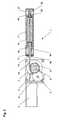
- the drive 1 shows the mechanical components of a drive 1, the housing of the drive 1, within which these components are arranged, not being shown here for reasons of clarity.
- the drive 1 has a rotatable output member designed as an output shaft 8 and is arranged in a known manner on or in a pivotably mounted wing or on or in a stationary frame, a force-transmitting linkage, not shown, being rotatably connected to the output shaft 8.
- a worm 3 is rotatably mounted, which with a first, on a shaft 5 mounted in the drive rotatably arranged Gear 4 meshes.
- a second gear 6 is non-rotatable arranged, the diameter of which is smaller than that of the first, with the screw 3 meshing gear 4.
- This smaller gear 6 meshes with a third, on the output shaft 8 of the drive 1 rotatably arranged gear 7, the Diameter is larger than that of the second gear 6.
- a cam 9 is arranged on which a flat belt 10 is guided around the circumference. The flat belt is through one Opening inserted into a spring housing 11.
- a contactor 12 which interacts with a rotation angle sensor 13 non-rotatably arranged on the output shaft 8.
- the contactor 12 can be used as a cam disk be formed and the angle of rotation sensor 13 as from the cam actuated electrical switch, possibly also from a combination multiple switches. Also using other types of suitable rotation angle sensors, e.g. Incremental encoder or potentiometer is conceivable, as well an arrangement elsewhere in the drive, e.g. on the shaft of the drive motor 2 or as a linear encoder in the spring housing.
- the output signal of the Angle of rotation sensor 13 is fed to a control device of the drive.
- the contactor 12 can be adjustable relative to the output shaft 8 in such a way that at a desired position of the movable to the drive 1 connected Wing, e.g. when fully opened, an output signal of the rotation angle sensor 13 is generated and then the drive motor 2 via the Control device is switched off.
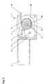
- the interior of the spring housing 11 can be seen in Fig. 2 .
- a cover 17 is arranged on the side of the elongated spring housing 11 facing the drive motor 2.
- the adjusting device 15 of a threaded sleeve 16 extends out of the spring housing 11 through a central opening of the cover 17.
- the threaded sleeve 16 has an annular collar which is supported on the cover 17 within the spring housing 11.
- the area of the threaded sleeve 16 which extends into the interior of the spring housing 11 has an external thread which interacts with the internal thread of an adjusting nut 18.
- the adjusting nut 18 can be displaced parallel to the longitudinal axis of the spring housing 11, but is secured against rotation relative to the spring housing 11 by means of an anti-rotation device, not shown.
- the adjusting device 15 of the threaded sleeve 16 can be designed as a hexagon for engaging a corresponding tool. Rotation of the threaded sleeve 16 thus causes the adjusting nut 18 to be displaced parallel to the longitudinal axis of the spring housing 11.
- the closer spring 19 acts the spring plate 20 in the drawing to the right, so that there is a tensile stress of the flat belt 10 results.
- Adjustment device 15 of the threaded sleeve 16 enables adjustment of the Preload of the closer spring 19.
- the drive motor 2 If the drive motor 2 is energized in the opening direction, it causes the from Auger 3 and the gears 4, 6, 7 existing gears a rotation of the Output shaft 8 counterclockwise. About the power transmission, not shown This rotary motion of the output shaft 8 becomes a linkage Opening movement of the movable wing implemented.
- the rotation of the Output shaft 8 is caused by the rotationally fixed coupling with cam 9 a rotation in the same direction.
- the flat belt 10 is thus out pulled out of the spring housing 11 and wound on the cam 9. At the same time, the flat belt 10 pulls the spring plate 20 under compression of the NO spring 19 in the drawing to the left.
- the fastening of the flat belt 10 to the cam 9 can be seen from FIG. 3 .
- the cam 9 has a receiving opening 26 which is formed as a secant-like opening in the cam 9 located in the edge region of the cam 9.
- the cross section of the receiving opening 26 is rectangular and somewhat larger than the cross section of the flat belt 10.
- Fig. 4 and Fig. 5 each show the area of the spring housing 11 of the drive in an enlarged view, namely two embodiments of the fixing of the flat belt 10 on the spring plate 20.
- the spring plate 20 each has a sleeve 27 with a central bore through which the Flat belt 10 is guided.
- the belt end 29 of the flat belt 10 is guided through this hole.
- the belt end 29 is then guided around a bolt 21 to form a loop 22 and again inserted into the bore of the sleeve 27, so that two layers of the flat belt 10 lie one on top of the other in the area of the bore of the sleeve 27.
- the bore in the sleeve 27 of the spring plate 20 is of constant diameter.
- the layers of the flat belt 10 lying one on top of the other are fixed by means of two clamping jaws 23, which can be clamped against the bore of the sleeve 27 by a clamping screw 28 which is adjustable in a threaded bore of the sleeve.
- a clamping screw can be dispensed with.
- the bore in the sleeve 27 tapers towards the interior of the spring housing 11, the two clamping jaws 23 being complementarily tapered to taper the bore.
- the spring plate 20 is acted upon by the closer spring 19 to the right in the drawing, the clamping jaws 23 with the layers of the flat belt 10 lying therebetween are pressed into the tapering inner surface of the bore in the sleeve 23. There is a frictional engagement and thus a fixation of the flat belt 10 to the spring plate 20.
- the loop 22 prevents the flat belt 10 with the bolt 21 therein additionally slipping out of the belt end 29 of the flat belt 10 from the spring plate 20.
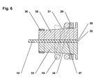
- Fig. 6 shows another embodiment of the fixation of the flat belt 10 on the spring plate 20 in an enlarged view.
- the belt end 37 of the flat belt 10 is clamped between the clamping surfaces 32, 35 of two clamping jaws 30, 33.
- the clamping jaws 30, 33 are each shaped in accordance with a half truncated cone, so that in the assembled state, that is to say with opposing clamping surfaces 32, 35 and the intermediate belt end 37, a truncated cone-like shape of the surfaces 31, 34 of the clamping jaws 30, 33 results, the diameter of The truncated cone rises slightly to the right in the drawing.
- the spring plate 20 is annular, its inner diameter being larger than the smallest diameter of the truncated cone formed by the clamping jaws 30, 33 and smaller than the largest diameter of this truncated cone.
- the clamping is thus achieved in that the spring plate 20 acted upon by the closer spring 19 is pressed to the right in the drawing, whereby it comes into contact with the surfaces 31, 34 of the clamping jaws 30, 33 and presses them together, as a result of which the clamping surfaces 32 , 35 lying belt end 37 of the flat belt is clamped.
- the clamping surfaces 32, 35 can have a surface that increases the friction value, for example corrugation, or a coating with a high coefficient of friction.
- a ring 36 subsequently mounted in the area of the smallest diameter of the truncated cone formed by the clamping jaws 30, 33 additionally secures the clamping connection.
Landscapes
- Business, Economics & Management (AREA)
- Emergency Management (AREA)
- Power-Operated Mechanisms For Wings (AREA)
- Seal Device For Vehicle (AREA)
- Window Of Vehicle (AREA)
Applications Claiming Priority (2)
| Application Number | Priority Date | Filing Date | Title |
|---|---|---|---|
| DE10301016 | 2003-01-13 | ||
| DE10301016A DE10301016B4 (de) | 2003-01-13 | 2003-01-13 | Antrieb für einen Flügel, insbesondere einer Tür oder eines Fensters |
Publications (3)
| Publication Number | Publication Date |
|---|---|
| EP1437476A2 true EP1437476A2 (fr) | 2004-07-14 |
| EP1437476A3 EP1437476A3 (fr) | 2007-08-01 |
| EP1437476B1 EP1437476B1 (fr) | 2008-09-24 |
Family
ID=32478224
Family Applications (1)
| Application Number | Title | Priority Date | Filing Date |
|---|---|---|---|
| EP03029536A Expired - Lifetime EP1437476B1 (fr) | 2003-01-13 | 2003-12-22 | Entraînement pour un panneau, en particulier un panneau de porte ou de fenêtre |
Country Status (4)
| Country | Link |
|---|---|
| EP (1) | EP1437476B1 (fr) |
| AT (1) | ATE409268T1 (fr) |
| DE (2) | DE10301016B4 (fr) |
| NO (1) | NO327625B1 (fr) |
Cited By (4)
| Publication number | Priority date | Publication date | Assignee | Title |
|---|---|---|---|---|
| EP2617924A3 (fr) * | 2012-01-19 | 2014-12-03 | DORMA GmbH + Co. KG | Actionnement de porte |
| DE102013112327A1 (de) | 2013-11-08 | 2015-05-13 | Gu Automatic Gmbh | Antrieb für einen Türflügel oder einen Fensterflügel |
| CN105683474A (zh) * | 2013-10-18 | 2016-06-15 | 美国耶鲁安全公司 | 用于提供来自闭门器或操作器的恒定的扭矩输出的设备 |
| EP3361033A1 (fr) * | 2017-02-08 | 2018-08-15 | GEZE GmbH | Procédé de mise en service d'un dispositif de fermeture de porte ou de fenêtre |
Families Citing this family (2)
| Publication number | Priority date | Publication date | Assignee | Title |
|---|---|---|---|---|
| DE102007030376B3 (de) * | 2007-06-29 | 2008-07-17 | Geze Gmbh | Antriebsanordnung für einen Drehflügel |
| DE102009045304B4 (de) | 2009-10-02 | 2014-02-27 | Geze Gmbh | Antriebsvorrichtung |
Citations (1)
| Publication number | Priority date | Publication date | Assignee | Title |
|---|---|---|---|---|
| DE19500944A1 (de) * | 1994-08-26 | 1996-02-29 | Geze Gmbh & Co | Antrieb für einen Flügel einer Tür, Fenster oder dergleichen |
Family Cites Families (1)
| Publication number | Priority date | Publication date | Assignee | Title |
|---|---|---|---|---|
| AT405861B (de) * | 1995-11-09 | 1999-12-27 | Liberda Viktor | Schwenktor bzw. falttor |
-
2003
- 2003-01-13 DE DE10301016A patent/DE10301016B4/de not_active Withdrawn - After Issue
- 2003-12-22 DE DE50310538T patent/DE50310538D1/de not_active Expired - Lifetime
- 2003-12-22 EP EP03029536A patent/EP1437476B1/fr not_active Expired - Lifetime
- 2003-12-22 AT AT03029536T patent/ATE409268T1/de active
-
2004
- 2004-01-12 NO NO20040131A patent/NO327625B1/no not_active IP Right Cessation
Patent Citations (1)
| Publication number | Priority date | Publication date | Assignee | Title |
|---|---|---|---|---|
| DE19500944A1 (de) * | 1994-08-26 | 1996-02-29 | Geze Gmbh & Co | Antrieb für einen Flügel einer Tür, Fenster oder dergleichen |
Cited By (7)
| Publication number | Priority date | Publication date | Assignee | Title |
|---|---|---|---|---|
| EP2617924A3 (fr) * | 2012-01-19 | 2014-12-03 | DORMA GmbH + Co. KG | Actionnement de porte |
| CN105683474A (zh) * | 2013-10-18 | 2016-06-15 | 美国耶鲁安全公司 | 用于提供来自闭门器或操作器的恒定的扭矩输出的设备 |
| US10030425B2 (en) | 2013-10-18 | 2018-07-24 | Yale Security Inc. | Apparatus for providing constant torque output from a door closer or operator |
| DE102013112327A1 (de) | 2013-11-08 | 2015-05-13 | Gu Automatic Gmbh | Antrieb für einen Türflügel oder einen Fensterflügel |
| DE102013112327B4 (de) * | 2013-11-08 | 2016-12-22 | Gu Automatic Gmbh | Antrieb für einen Türflügel oder einen Fensterflügel |
| EP3361033A1 (fr) * | 2017-02-08 | 2018-08-15 | GEZE GmbH | Procédé de mise en service d'un dispositif de fermeture de porte ou de fenêtre |
| US10626653B2 (en) | 2017-02-08 | 2020-04-21 | Geze Gmbh | Method for the commissioning of a door or window closer |
Also Published As
| Publication number | Publication date |
|---|---|
| NO20040131L (no) | 2004-07-14 |
| EP1437476A3 (fr) | 2007-08-01 |
| ATE409268T1 (de) | 2008-10-15 |
| DE10301016A1 (de) | 2004-07-29 |
| DE50310538D1 (de) | 2008-11-06 |
| DE10301016B4 (de) | 2006-05-04 |
| NO327625B1 (no) | 2009-09-07 |
| EP1437476B1 (fr) | 2008-09-24 |
Similar Documents
| Publication | Publication Date | Title |
|---|---|---|
| EP0731289B1 (fr) | Dispositif d'entraínement de toits ouvrants, lève-glaces ou similaires | |
| EP0410487B1 (fr) | Commande de secours pour un élément d'entraînement par éléctromoteur | |
| DE202005008151U1 (de) | Antriebsanordnung für verstellbare Funktionselemente in einem Kraftfahrzeug | |
| DE102006049840B4 (de) | Gurtaufroller für einen Fahrzeuginsassen-Sicherheitsgurt | |
| EP3708753B1 (fr) | Ferrure de couvercle destinée à la fixation pivotante d'un couvercle de meuble sur un corps de meuble | |
| EP3733349B1 (fr) | Dispositif de serrage pour un raccordement à vis | |
| DE102009006946B4 (de) | Tür, insbesondere Kraftfahrzeugtür | |
| DE102009036872B4 (de) | Türeinheit | |
| EP1437476B1 (fr) | Entraînement pour un panneau, en particulier un panneau de porte ou de fenêtre | |
| EP1020603A2 (fr) | Mécanisme d'entraínement d'une porte battante | |
| EP1046000B1 (fr) | Dispositif pour deplacer une piece, notamment dans un vehicule a moteur, comportant un mecanisme de reglage | |
| EP2305936A2 (fr) | Dispositif d'entraînement | |
| DE102006011083A1 (de) | Kraftfahrzeugschloß | |
| DE10356614A1 (de) | Motorisierter Sitz zum Drehen der Lehne und Verfahren | |
| EP0622260A1 (fr) | Dispositif d'actionnement de parties mobiles pour véhicule | |
| DE102007008492A1 (de) | Übertragungsvorrichtung zur Übertragung eines Drehmoments | |
| DE102005002232A1 (de) | Verschluss für einen Treibstangenbeschlag | |
| EP2248958B1 (fr) | Fenêtre coulissante de toit | |
| EP1870553B1 (fr) | Dispositif destiné à la fermeture conséquente de portes rotatives à deux battants | |
| DE102019110911B4 (de) | Türfeststeller | |
| EP1102908B1 (fr) | Arret de porte | |
| DE19861278B4 (de) | Spindel- oder Schneckenantrieb für Verstelleinrichtungen in Kraftfahrzeugen | |
| DE202005004042U1 (de) | Kraftfahrzeugschloß | |
| DE10207041B4 (de) | Betätigungseinrichtung zum Verstellen einer schwenkbaren Kraftfahrzeugtür | |
| DE102004036361C5 (de) | Gurtbringer für ein Kraftfahrzeug |
Legal Events
| Date | Code | Title | Description |
|---|---|---|---|
| PUAI | Public reference made under article 153(3) epc to a published international application that has entered the european phase |
Free format text: ORIGINAL CODE: 0009012 |
|
| AK | Designated contracting states |
Kind code of ref document: A2 Designated state(s): AT BE BG CH CY CZ DE DK EE ES FI FR GB GR HU IE IT LI LU MC NL PT RO SE SI SK TR |
|
| AX | Request for extension of the european patent |
Extension state: AL LT LV MK |
|
| PUAL | Search report despatched |
Free format text: ORIGINAL CODE: 0009013 |
|
| AK | Designated contracting states |
Kind code of ref document: A3 Designated state(s): AT BE BG CH CY CZ DE DK EE ES FI FR GB GR HU IE IT LI LU MC NL PT RO SE SI SK TR |
|
| AX | Request for extension of the european patent |
Extension state: AL LT LV MK |
|
| 17P | Request for examination filed |
Effective date: 20080123 |
|
| GRAP | Despatch of communication of intention to grant a patent |
Free format text: ORIGINAL CODE: EPIDOSNIGR1 |
|
| AKX | Designation fees paid |
Designated state(s): AT BE BG CH CY CZ DE DK EE ES FI FR GB GR HU IE IT LI LU MC NL PT RO SE SI SK TR |
|
| GRAS | Grant fee paid |
Free format text: ORIGINAL CODE: EPIDOSNIGR3 |
|
| GRAA | (expected) grant |
Free format text: ORIGINAL CODE: 0009210 |
|
| AK | Designated contracting states |
Kind code of ref document: B1 Designated state(s): AT BE BG CH CY CZ DE DK EE ES FI FR GB GR HU IE IT LI LU MC NL PT RO SE SI SK TR |
|
| REG | Reference to a national code |
Ref country code: GB Ref legal event code: FG4D Free format text: NOT ENGLISH |
|
| REG | Reference to a national code |
Ref country code: CH Ref legal event code: EP |
|
| REG | Reference to a national code |
Ref country code: IE Ref legal event code: FG4D Free format text: LANGUAGE OF EP DOCUMENT: GERMAN |
|
| REF | Corresponds to: |
Ref document number: 50310538 Country of ref document: DE Date of ref document: 20081106 Kind code of ref document: P |
|
| REG | Reference to a national code |
Ref country code: SE Ref legal event code: TRGR |
|
| PG25 | Lapsed in a contracting state [announced via postgrant information from national office to epo] |
Ref country code: FI Free format text: LAPSE BECAUSE OF FAILURE TO SUBMIT A TRANSLATION OF THE DESCRIPTION OR TO PAY THE FEE WITHIN THE PRESCRIBED TIME-LIMIT Effective date: 20080924 Ref country code: SI Free format text: LAPSE BECAUSE OF FAILURE TO SUBMIT A TRANSLATION OF THE DESCRIPTION OR TO PAY THE FEE WITHIN THE PRESCRIBED TIME-LIMIT Effective date: 20080924 |
|
| REG | Reference to a national code |
Ref country code: IE Ref legal event code: FD4D |
|
| PG25 | Lapsed in a contracting state [announced via postgrant information from national office to epo] |
Ref country code: ES Free format text: LAPSE BECAUSE OF FAILURE TO SUBMIT A TRANSLATION OF THE DESCRIPTION OR TO PAY THE FEE WITHIN THE PRESCRIBED TIME-LIMIT Effective date: 20090104 Ref country code: BG Free format text: LAPSE BECAUSE OF FAILURE TO SUBMIT A TRANSLATION OF THE DESCRIPTION OR TO PAY THE FEE WITHIN THE PRESCRIBED TIME-LIMIT Effective date: 20081224 |
|
| PG25 | Lapsed in a contracting state [announced via postgrant information from national office to epo] |
Ref country code: CZ Free format text: LAPSE BECAUSE OF FAILURE TO SUBMIT A TRANSLATION OF THE DESCRIPTION OR TO PAY THE FEE WITHIN THE PRESCRIBED TIME-LIMIT Effective date: 20080924 Ref country code: PT Free format text: LAPSE BECAUSE OF FAILURE TO SUBMIT A TRANSLATION OF THE DESCRIPTION OR TO PAY THE FEE WITHIN THE PRESCRIBED TIME-LIMIT Effective date: 20090224 Ref country code: RO Free format text: LAPSE BECAUSE OF FAILURE TO SUBMIT A TRANSLATION OF THE DESCRIPTION OR TO PAY THE FEE WITHIN THE PRESCRIBED TIME-LIMIT Effective date: 20080924 Ref country code: SK Free format text: LAPSE BECAUSE OF FAILURE TO SUBMIT A TRANSLATION OF THE DESCRIPTION OR TO PAY THE FEE WITHIN THE PRESCRIBED TIME-LIMIT Effective date: 20080924 |
|
| BERE | Be: lapsed |
Owner name: GEZE G.M.B.H. Effective date: 20081231 |
|
| PG25 | Lapsed in a contracting state [announced via postgrant information from national office to epo] |
Ref country code: DK Free format text: LAPSE BECAUSE OF FAILURE TO SUBMIT A TRANSLATION OF THE DESCRIPTION OR TO PAY THE FEE WITHIN THE PRESCRIBED TIME-LIMIT Effective date: 20080924 Ref country code: MC Free format text: LAPSE BECAUSE OF NON-PAYMENT OF DUE FEES Effective date: 20081231 Ref country code: EE Free format text: LAPSE BECAUSE OF FAILURE TO SUBMIT A TRANSLATION OF THE DESCRIPTION OR TO PAY THE FEE WITHIN THE PRESCRIBED TIME-LIMIT Effective date: 20080924 Ref country code: IE Free format text: LAPSE BECAUSE OF FAILURE TO SUBMIT A TRANSLATION OF THE DESCRIPTION OR TO PAY THE FEE WITHIN THE PRESCRIBED TIME-LIMIT Effective date: 20080924 |
|
| PLBE | No opposition filed within time limit |
Free format text: ORIGINAL CODE: 0009261 |
|
| STAA | Information on the status of an ep patent application or granted ep patent |
Free format text: STATUS: NO OPPOSITION FILED WITHIN TIME LIMIT |
|
| 26N | No opposition filed |
Effective date: 20090625 |
|
| PG25 | Lapsed in a contracting state [announced via postgrant information from national office to epo] |
Ref country code: BE Free format text: LAPSE BECAUSE OF NON-PAYMENT OF DUE FEES Effective date: 20081231 |
|
| PG25 | Lapsed in a contracting state [announced via postgrant information from national office to epo] |
Ref country code: HU Free format text: LAPSE BECAUSE OF FAILURE TO SUBMIT A TRANSLATION OF THE DESCRIPTION OR TO PAY THE FEE WITHIN THE PRESCRIBED TIME-LIMIT Effective date: 20090325 Ref country code: LU Free format text: LAPSE BECAUSE OF NON-PAYMENT OF DUE FEES Effective date: 20081222 Ref country code: CY Free format text: LAPSE BECAUSE OF FAILURE TO SUBMIT A TRANSLATION OF THE DESCRIPTION OR TO PAY THE FEE WITHIN THE PRESCRIBED TIME-LIMIT Effective date: 20080924 |
|
| PG25 | Lapsed in a contracting state [announced via postgrant information from national office to epo] |
Ref country code: TR Free format text: LAPSE BECAUSE OF FAILURE TO SUBMIT A TRANSLATION OF THE DESCRIPTION OR TO PAY THE FEE WITHIN THE PRESCRIBED TIME-LIMIT Effective date: 20080924 |
|
| PG25 | Lapsed in a contracting state [announced via postgrant information from national office to epo] |
Ref country code: GR Free format text: LAPSE BECAUSE OF FAILURE TO SUBMIT A TRANSLATION OF THE DESCRIPTION OR TO PAY THE FEE WITHIN THE PRESCRIBED TIME-LIMIT Effective date: 20081225 |
|
| REG | Reference to a national code |
Ref country code: FR Ref legal event code: PLFP Year of fee payment: 13 |
|
| REG | Reference to a national code |
Ref country code: FR Ref legal event code: PLFP Year of fee payment: 14 |
|
| REG | Reference to a national code |
Ref country code: FR Ref legal event code: PLFP Year of fee payment: 15 |
|
| PGFP | Annual fee paid to national office [announced via postgrant information from national office to epo] |
Ref country code: SE Payment date: 20221222 Year of fee payment: 20 Ref country code: NL Payment date: 20221222 Year of fee payment: 20 Ref country code: GB Payment date: 20221222 Year of fee payment: 20 Ref country code: FR Payment date: 20221222 Year of fee payment: 20 Ref country code: DE Payment date: 20221231 Year of fee payment: 20 Ref country code: AT Payment date: 20221222 Year of fee payment: 20 |
|
| PGFP | Annual fee paid to national office [announced via postgrant information from national office to epo] |
Ref country code: CH Payment date: 20230103 Year of fee payment: 20 |
|
| PGFP | Annual fee paid to national office [announced via postgrant information from national office to epo] |
Ref country code: IT Payment date: 20221228 Year of fee payment: 20 |
|
| REG | Reference to a national code |
Ref country code: DE Ref legal event code: R071 Ref document number: 50310538 Country of ref document: DE |
|
| REG | Reference to a national code |
Ref country code: NL Ref legal event code: MK Effective date: 20231221 |
|
| REG | Reference to a national code |
Ref country code: CH Ref legal event code: PL |
|
| REG | Reference to a national code |
Ref country code: GB Ref legal event code: PE20 Expiry date: 20231221 |
|
| PG25 | Lapsed in a contracting state [announced via postgrant information from national office to epo] |
Ref country code: GB Free format text: LAPSE BECAUSE OF EXPIRATION OF PROTECTION Effective date: 20231221 |
|
| REG | Reference to a national code |
Ref country code: SE Ref legal event code: EUG |
|
| PG25 | Lapsed in a contracting state [announced via postgrant information from national office to epo] |
Ref country code: GB Free format text: LAPSE BECAUSE OF EXPIRATION OF PROTECTION Effective date: 20231221 |
|
| REG | Reference to a national code |
Ref country code: AT Ref legal event code: MK07 Ref document number: 409268 Country of ref document: AT Kind code of ref document: T Effective date: 20231222 |