EP1437322A1 - Treibscheibenaufzug - Google Patents
Treibscheibenaufzug Download PDFInfo
- Publication number
- EP1437322A1 EP1437322A1 EP03022347A EP03022347A EP1437322A1 EP 1437322 A1 EP1437322 A1 EP 1437322A1 EP 03022347 A EP03022347 A EP 03022347A EP 03022347 A EP03022347 A EP 03022347A EP 1437322 A1 EP1437322 A1 EP 1437322A1
- Authority
- EP
- European Patent Office
- Prior art keywords
- traction sheave
- elevator
- diameter
- elevator car
- counterweight
- Prior art date
- Legal status (The legal status is an assumption and is not a legal conclusion. Google has not performed a legal analysis and makes no representation as to the accuracy of the status listed.)
- Granted
Links
- 239000000725 suspension Substances 0.000 claims abstract description 42
- 229910000831 Steel Inorganic materials 0.000 claims description 11
- 239000010959 steel Substances 0.000 claims description 11
- 239000000463 material Substances 0.000 claims description 4
- 230000005484 gravity Effects 0.000 claims description 3
- 230000002093 peripheral effect Effects 0.000 claims description 3
- 229910001060 Gray iron Inorganic materials 0.000 claims description 2
- 108010066114 cabin-2 Proteins 0.000 description 4
- 238000010276 construction Methods 0.000 description 4
- 238000005452 bending Methods 0.000 description 3
- 230000008901 benefit Effects 0.000 description 2
- 229910001018 Cast iron Inorganic materials 0.000 description 1
- 230000005540 biological transmission Effects 0.000 description 1
- 238000010586 diagram Methods 0.000 description 1
Images

Classifications
-
- B—PERFORMING OPERATIONS; TRANSPORTING
- B66—HOISTING; LIFTING; HAULING
- B66B—ELEVATORS; ESCALATORS OR MOVING WALKWAYS
- B66B11/00—Main component parts of lifts in, or associated with, buildings or other structures
- B66B11/0065—Roping
- B66B11/008—Roping with hoisting rope or cable operated by frictional engagement with a winding drum or sheave
Definitions
- the invention relates to a traction sheave elevator Elevator car that can be moved along guide rails, and with a counterweight also guided on rails, with Catenary ropes on which the elevator car and the counterweight are attached, and with a drive consisting of a motor, a traction sheave for the suspension cables and a brake, which drive in the upper area of the elevator shaft between the shaft wall and the space that the elevator car in its top position needed, and / or in a vertical Essentially extending this range upwards is arranged, the motor shaft and the traction sheave shaft coaxial and approximately horizontal and parallel to the neighboring one Shaft wall and / or oriented to the adjacent cabin wall are, with the suspension provided on the suspension cable between the elevator car and the counterweight by at least at least one deflection roller engaging on the elevator car 2: 1 is reduced
- Such a traction sheave elevator is known from WO 99/43589.
- a ratio of the diameter is the Deflection roller to the diameter of the suspension cable and / or a Ratio of the diameter of the traction sheave to the diameter of the suspension rope of less than 40: 1. Be reached this is due to the fact that the suspension ropes are flat ropes or Straps are formed, which means that they are special suspension elements with corresponding additional effort required.
- the or Cables have an approximately circular cross-section that the Ratio of the diameter of the deflection roller to the diameter of the Carrier rope and / or the ratio of the diameter of the Traction sheave to the diameter of the suspension cable equal to 35: 1 or is smaller that the suspension rope or ropes is / are steel ropes and that the traction sheave and all at the elevator car and at the counterweight provided pulleys in a common Level are arranged so that the suspension cable or the multiple Catenary strands from the traction sheave to the pulley or conversely essentially undeflected to the side run.
- the suspension rope can be of a relatively small diameter and accordingly, especially with a small bending radius be because of the bends and counterbends between the traction sheave and located on the cabin and on the counterweight Deflection pulleys take place in one plane and deflections out this level towards the side that the rope additionally would be avoided in this area of the rope guide become. Because the bends and counter-bends of the suspension cable or of the suspension rope strands essentially to the side If the rope is undeflected, the rope can be used for relatively small Bending radii nevertheless achieve the longest possible service life and traction sheave and pulleys can be correspondingly small Have diameters, so that the space required accordingly is reduced.
- the diameter of the traction sheave is larger than the diameter of the deflection rollers.
- the driving force from the traction sheave to the Carrier rope or the suspension rope strands are transmitted.
- a further expedient embodiment of the invention can be found therein exist that the traction sheave and / or the pulley or Deflection rollers at least in the area of their rope groove or rope grooves made of a material with a higher coefficient of friction as steel or cast iron, in particular made of plastic.
- An improved coefficient of friction enables that too lighter elevator cars can be attached to the rope, and less slip between the traction sheave and / or pulley and rope also results in a longer one Lifetime of the rope.
- the traction sheave can be directly on the output of the drive motor arranged and the drive of the traction sheave elevator be gearless. Because the need for moments at the Traction sheave reduced by the aforementioned 2: 1 suspension a transmission can be saved.
- At the cabin two can be in the same plane as the traction sheave arranged deflection rollers can be provided. This leaves the suspension of the elevator car improve and through distribute the load caused by the suspension.
- the pulley or pulleys can be on the roof of the elevator car compared to the cabin walls in terms of their Storage must be set back so far that the levels, in which the cabin walls are arranged, tangential to the deflection rollers run or a distance to the nearest Have peripheral area of the pulleys. This does not result only a cheap suspension of the elevator car, in which the Center of gravity located below the actual suspension but also minimizes the shaft width, because next to the cabin there is no space for one under the elevator cabin rope to be passed through is required.
- the traction sheave and / or the deflection roller on the elevator car and / or on the counterweight can have a diameter of about Have 32 cm or less. This leads to the desired small bending radii and the ratio of Washer or pulley diameter to rope diameter with the smallest possible rope diameter.
- the elevator car can be hung in a backpack design to make the best possible use of the space within the shaft a solution for simple assembly and / or for to offer special cabins.
- the diameter of the suspension cable can be about 8 mm or less. Weight can also be saved because of the Reduction of the rope diameter can the traction sheave and the load torque of the motor can be kept smaller.
- suspension cables are steel cables with a steel core.
- the pulley attacking the cabin or in a common one Level on the cab attacking several pulleys can be approximately in the middle of the elevator car or approximately in the plane parallel to the center of gravity of the elevator car be arranged to two cabin walls. So that is Elevator cab already largely aligned due to its suspension.
- the one formed by the two guide rails for the elevator car Level and the level formed by the guide rails can be arranged parallel or perpendicular to each other. It can be a backpack construction, but also a construction for Application where the suspension forces are not - how in the backpack design - one-sided in the elevator car initiated and passed on to appropriate guides have to.
- the drive is as light as possible, which is correspondingly simple inside the elevator shaft can be installed, while the rope suspension is as simple as possible, so that costs are also reduced become. This is achieved in that the required Torque and thus that for the drive and the operation of the Elevator car required material including the ropes and pulleys are minimized. At the same time, the Rope life and driftability increased.
- the drive of the traction sheave elevator according to the invention can for example, configured in this way and in the elevator shaft be mounted or housed, as in DE 100 64 850 C2 is described.
- a traction sheave elevator designated as a whole has one Elevator car 2, which in a known manner along not Guide rails shown in more detail within an elevator shaft 3 is vertically movable. Furthermore belongs to this Traction sheave elevator 1 also not shown Rail-guided counterweight 4 and the elevator car 2 and the counterweight 4 are approximately circular in cross section Support ropes 5 attached.
- Fig. 2 is a drive 6, consisting of a motor, a Traction sheave 7 indicated for the supporting cables 5 and a brake, which drive 6 according to FIGS. 1 and 3 in the upper region of the Elevator shaft 3 between the shaft wall 8 and the room the elevator car 2 needs in its upper position, or in a vertical extension of this space essentially is arranged.
- the motor shaft and the traction sheave shaft are thereby coaxial and approximately horizontal and parallel to adjacent shaft wall 8 and also to the adjacent cabin wall oriented.
- the rope guide takes place from the traction sheave 7 to the deflection rollers 9 essentially without inclined entry of the ropes onto the pulleys and without twisting the rope erection between the pulleys 9 and the traction sheave 7, so that unnecessary lateral bends of the support cable or 5 can be avoided.
- the traction sheave 7 is directly on the output of the drive motor arranged and the drive 6 of this traction sheave elevator 1 is gearless in both exemplary embodiments.
- the traction sheave 7 and the deflection rollers can 9 and 11 at least in the area of their rope groove or rope grooves made of a material with a higher coefficient of friction than steel or gray cast iron, in particular made of plastic, so that lighter cabins 2 used due to the better coefficient of friction can be and a lesser or completely avoided Slip between rope 5 and the respective disc 7 or roller 9 or 11 enables a longer lifespan of the rope 5.
- the deflection rollers 9 are on the roof 10 opposite the elevator car 2 the cabin walls with regard to their storage 12 only set back so far that the levels in which the cabin walls are arranged, approximately tangentially to the deflection rollers according to FIG. 2 9 run or a short distance from the have the closest peripheral area of the folding rollers 9, wherein the projection of the deflection rollers 9 according to FIG. 2 slightly survive this distance over the canopy 10 can so that the cabin 2 also in the area of the traction sheave 7 can be run as high as possible.
- the traction sheave 7 and the deflecting rollers 9 and 11 about a matching diameter of to Example having about 32 cm or less is according to FIGS. 1 and 3 the traction sheave diameter is slightly larger than the diameter the pulleys selected.
- the diameter of the suspension cable can be in in such a case, be about eight mm or less, so that there is a ratio of the diameter of the deflection roller 9 or 11 to the diameter of the support cable 5 and the ratio of Diameter of the traction sheave 7 to the diameter of the suspension cable 5 of about 35: 1 or less, which is a space-saving Construction benefits.
- the suspension cables are 5 in expediently steel ropes with steel core, what opposite special belt constructions or flat ropes cheaper is.
- the drive 6 of a traction sheave elevator 1 should be as possible have low weight and as simple as possible in the upper area of the elevator shaft 3 of a traction sheave elevator 1 installed can be.
- the one provided on the supporting cable 5 Suspension between the elevator car 2 and the associated counterweight 4 preferably by at least one on the elevator car 2 on the roof 10 attacking pulley 9 at least Reduced 2: 1 to at least the required torque cut in half.
- the elevator car 2 provided deflection roller 9 and the traction sheave 7 in a common Level arranged so that the suspension cable 5 or the several suspension rope strands from the traction sheave 7 to the deflection roller 9 or vice versa essentially undeflected towards the side run, bend and counterbend only in one level takes place what is a rope with a circular cross section allowed with a comparatively small diameter, so that the ratio of the diameter of the guide roller 9 to Diameter of the support cable 5 and / or the ratio of the diameter the traction sheave 7 to the diameter of the supporting cable 5 can be equal to or less than 35: 1, which also causes the weight of the drive can be reduced.
- the drive can be attached and arranged in such a way that as described in DE 100 64 850 C2.
Abstract
Description
- Fig. 1
- das Schema eines maschinenraumlosen Aufzugs mit einer an zwei Umlenkrollen aufgehängten Aufzugskabine, wobei eine Seilaufhängung mit einem Untersetzungsverhältnis von 2:1 vorgesehen ist und die Treibscheibe des Antriebs, die Umlenkrollen an der Aufzugskabine und die Umlenkrolle an dem Gegengewicht in einer gemeinsamen Ebene angeordnet sind,
- Fig. 2
- einen Querschnitt eines Aufzugsschachts mit Draufsicht auf die Aufzugskabine und ihren Antrieb gemäß Fig. 1, wobei die mehrlagigen Umlenkrollen und die mehrlagige Treibscheibe in der selben Ebene angeordnet sind,
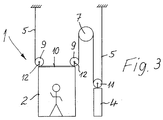
- Fig. 3
- eine der Fig. 1 entsprechende Darstellung, bei welcher der Aufhängungspunkt für den von dem Gegenwicht kommenden Seilstrang gegenüber Fig. 1 anders gewählt ist.
Claims (12)
- Treibscheibenaufzug (1) mit einer Aufzugskabine (2), die entlang von Führungsschienen verfahrbar ist, und mit einem ebenfalls an Schienen geführten Gegengewicht (4), mit Tragseilen (5), an denen die Aufzugskabine (2) und das Gegengewicht (4) angehängt sind, und mit einem Antrieb (6), bestehend aus einem Motor, einer Treibscheibe (7) für die Tragseile (5) und einer Bremse, welcher Antrieb (6) im oberen Bereich des Aufzugsschachts (3) zwischen der Schachtwand (8) und dem Raum, den die Aufzugskabine (2) in ihrer obersten Position benötigt, und/oder in einer vertikalen Verlängerung dieses Bereichs nach oben im wesentlichen angeordnet ist, wobei die Motorwelle und die Treibscheibenwelle koaxial und etwa horizontal sowie parallel zur benachbarten Schachtwand (8) und/oder zur benachbarten Kabinenwand orientiert sind, wobei die über das Tragseil (5) vorgesehene Aufhängung zwischen der Aufzugskabine (2) und dem Gegengewicht (4) durch zumindest eine an der Aufzugskabine (2) angreifende Umlenkrolle (9) wenigstens 2:1 untersetzt ist, dadurch gekennzeichnet, dass das oder die Tragseile (5) einen etwa kreisförmigen Querschnitt haben, dass das Verhältnis des Durchmessers der Umlenkrolle (9) zum Durchmesser des Tragseils (5) und/oder das Verhältnis des Durchmessers der Treibscheibe (7) zum Durchmesser des Tragseils (5) gleich 35:1 oder kleiner ist, dass das oder die Tragseile (5) Stahlseile ist/sind und dass die Treibscheibe (7) und alle an der Aufzugskabine (2) und an dem Gegengewicht (4) vorgesehenen Umlenkrollen (9, 11) in einer gemeinsamen Ebene angeordnet sind, so dass das Tragseil (5) oder die mehreren Tragseile von der Treibscheibe (7) zu der Umlenkrolle (9, 11) oder umgekehrt im Wesentlichen nach der Seite hin unausgelenkt verlaufen.
- Treibscheibenaufzug nach Anspruch 1, dadurch gekennzeichnet, dass der Durchmesser der Treibscheibe (7) größer als der Durchmesser der Umlenkrollen (9, 11) ist.
- Treibscheibenaufzug nach Anspruch 1 oder 2, dadurch gekennzeichnet, dass die Treibscheibe (7) und/oder die Umlenkrolle (9) oder Umlenkrollen (11) zumindest im Bereich ihrer Seilrille oder Seilrillen aus einem Werkstoff mit höherem Reibungskoeffizienten als Stahl oder Grauguss, insbesondere aus Kunststoff bestehen.
- Treibscheibenaufzug nach einem der Ansprüche 1 bis 3, dadurch gekennzeichnet, dass die Treibscheibe (7) unmittelbar auf dem Abtrieb des Antriebsmotors angeordnet und der Antrieb (6) des Treibscheibenaufzugs (1) getriebelos ausgebildet ist.
- Treibscheibenaufzug nach einem der Ansprüche 1 bis 4, dadurch gekennzeichnet, dass an der Kabine (2) zwei in derselben Ebene wie die Treibscheibe (7) angeordnete Umlenkrollen (9) vorgesehen sind.
- Treibscheibenaufzug nach einem der Ansprüche 1 bis 5, dadurch gekennzeichnet, dass die Umlenkrolle oder Umlenkrollen (9) auf dem Dach (10) der Aufzugskabine (2) gegenüber den Kabinenwänden hinsichtlich ihrer Lagerung nur soweit zurückversetzt angeordnet sind, dass die Ebenen, in denen die Kabinenwände angeordnet sind, tangential zu den Umlenkrollen (9) verlaufen oder einen Abstand zu dem nächstliegenden Umfangsbereich der Umlenkrollen (9) haben.
- Treibscheibenaufzug nach einem der Ansprüche 1 bis 6, dadurch gekennzeichnet, dass die Treibscheibe (7) und/oder die Umlenkrolle (9/11) an der Aufzugskabine (2) und/oder an dem Gegengewicht (4) einen Durchmesser von etwa 32 cm oder weniger hat.
- Treibscheibenaufzug nach einem der vorstehenden Ansprüche, dadurch gekennzeichnet, dass die Aufzugskabine (2) in Rucksack-Bauweise aufgehängt ist.
- Treibscheibenaufzug nach einem der Ansprüche 1 bis 8, dadurch gekennzeichnet, dass der Durchmesser des Tragseils (5) etwa gleich 8 mm oder weniger ist.
- Treibscheibenaufzug nach einem der Ansprüche 1 bis 9, dadurch gekennzeichnet, dass das oder die Tragseile (5) Stahlseile mit Stahlseele ist/sind.
- Treibscheibenaufzug nach einem der Ansprüche 1 bis 10, dadurch gekennzeichnet, dass die an der Kabine (2) angreifende Umlenkrolle (9) oder die in einer gemeinsamen Ebene an der Kabine (2) angreifenden Umlenkrollen (9) etwa mittig zur Aufzugskabine oder etwa in der durch den Schwerpunkt der Aufzugskabine (2) verlaufenden Ebene angeordnet sind.
- Treibscheibenaufzug nach einem der Ansprüche 1 bis 11, dadurch gekennzeichnet, dass die von den beiden Führungsschienen für die Aufzugskabine (2) gebildete Ebene und die von den Führungsschienen für das Gegengewicht (4) gebildete Ebene parallel oder senkrecht zueinander angeordnet sind.
Applications Claiming Priority (2)
| Application Number | Priority Date | Filing Date | Title |
|---|---|---|---|
| DE10257564A DE10257564A1 (de) | 2002-12-10 | 2002-12-10 | Treibscheibenaufzug |
| DE10257564 | 2002-12-10 |
Publications (2)
| Publication Number | Publication Date |
|---|---|
| EP1437322A1 true EP1437322A1 (de) | 2004-07-14 |
| EP1437322B1 EP1437322B1 (de) | 2006-11-29 |
Family
ID=32477494
Family Applications (1)
| Application Number | Title | Priority Date | Filing Date |
|---|---|---|---|
| EP03022347A Expired - Lifetime EP1437322B1 (de) | 2002-12-10 | 2003-10-04 | Treibscheibenaufzug |
Country Status (3)
| Country | Link |
|---|---|
| EP (1) | EP1437322B1 (de) |
| AT (1) | ATE346818T1 (de) |
| DE (2) | DE10257564A1 (de) |
Cited By (1)
| Publication number | Priority date | Publication date | Assignee | Title |
|---|---|---|---|---|
| WO2008001149A1 (en) | 2006-06-26 | 2008-01-03 | Otis Elevator Company | Elevator installation with reduced hoistway dimensions |
Citations (2)
| Publication number | Priority date | Publication date | Assignee | Title |
|---|---|---|---|---|
| WO1999043589A1 (en) * | 1998-02-26 | 1999-09-02 | Otis Elevator Company | Elevator system having drive motor located between elevator car and hoistway sidewall |
| DE10164548A1 (de) * | 2001-01-04 | 2002-09-12 | Wittur Ag | Getriebeloser Seilaufzug |
Family Cites Families (2)
| Publication number | Priority date | Publication date | Assignee | Title |
|---|---|---|---|---|
| DE1210530B (de) * | 1960-09-13 | 1966-02-10 | Silopark S A | Aufzugseinrichtung |
| DE3024177A1 (de) * | 1980-06-27 | 1982-01-21 | Westfälische Berggewerkschaftskasse, 4630 Bochum | Treibscheibe fuer foerdermaschinen oder haspel zum antrieb von foerderseilen |
-
2002
- 2002-12-10 DE DE10257564A patent/DE10257564A1/de not_active Withdrawn
-
2003
- 2003-10-04 DE DE50305830T patent/DE50305830D1/de not_active Expired - Lifetime
- 2003-10-04 AT AT03022347T patent/ATE346818T1/de active
- 2003-10-04 EP EP03022347A patent/EP1437322B1/de not_active Expired - Lifetime
Patent Citations (2)
| Publication number | Priority date | Publication date | Assignee | Title |
|---|---|---|---|---|
| WO1999043589A1 (en) * | 1998-02-26 | 1999-09-02 | Otis Elevator Company | Elevator system having drive motor located between elevator car and hoistway sidewall |
| DE10164548A1 (de) * | 2001-01-04 | 2002-09-12 | Wittur Ag | Getriebeloser Seilaufzug |
Cited By (2)
| Publication number | Priority date | Publication date | Assignee | Title |
|---|---|---|---|---|
| WO2008001149A1 (en) | 2006-06-26 | 2008-01-03 | Otis Elevator Company | Elevator installation with reduced hoistway dimensions |
| US9150384B2 (en) | 2006-06-26 | 2015-10-06 | Otis Elevator Company | Elevator installation with reduced hoistway dimensions |
Also Published As
| Publication number | Publication date |
|---|---|
| EP1437322B1 (de) | 2006-11-29 |
| DE50305830D1 (de) | 2007-01-11 |
| ATE346818T1 (de) | 2006-12-15 |
| DE10257564A1 (de) | 2004-07-08 |
Similar Documents
| Publication | Publication Date | Title |
|---|---|---|
| EP1446351B1 (de) | Aufzugssystem | |
| DE69931764T2 (de) | Aufzugssystem mit obenliegendem antriebsmotor | |
| DE69918218T2 (de) | Gezogener Aufzug | |
| EP0846645B1 (de) | Modular aufgebauter Aufzug | |
| DE69933199T2 (de) | Aufzugssystem mit einem zwischen der aufzugskabine und der schachtwand angeordneten antriebsmotor | |
| DE69908908T2 (de) | Maschinenraumloses aufzugssystem mit aufzugsantrieb im aufzugskabine | |
| EP1700809B1 (de) | Aufzuganlage | |
| EP1724226A1 (de) | Aufzugsanlage | |
| EP1935829A1 (de) | Aufzug mit zwei übereinander liegenden Aufzugskabinen in einem Schacht | |
| EP1234796B1 (de) | Anordnung für Gewichtsausgleichselemente | |
| DE60315027T2 (de) | Aufzug | |
| DE60315873T2 (de) | Antriebsscheibenaufzug ohne gegengewicht | |
| EP1437322B1 (de) | Treibscheibenaufzug | |
| EP1656318B9 (de) | Verfahren zur Montage eines Aufzugs | |
| AT410784B (de) | Aufzug | |
| EP1867597B1 (de) | Aufzug | |
| DE19963286B4 (de) | Aufzug | |
| EP1045811B1 (de) | Seil-aufzug mit treibscheibe | |
| DE20321733U1 (de) | Gegengewichtsloser Treibscheibenaufzug | |
| DE102005012137A1 (de) | Seilführung für einen Aufzug |
Legal Events
| Date | Code | Title | Description |
|---|---|---|---|
| PUAI | Public reference made under article 153(3) epc to a published international application that has entered the european phase |
Free format text: ORIGINAL CODE: 0009012 |
|
| AK | Designated contracting states |
Kind code of ref document: A1 Designated state(s): AT BE BG CH CY CZ DE DK EE ES FI FR GB GR HU IE IT LI LU MC NL PT RO SE SI SK TR |
|
| AX | Request for extension of the european patent |
Extension state: AL LT LV MK |
|
| 17P | Request for examination filed |
Effective date: 20040708 |
|
| AKX | Designation fees paid |
Designated state(s): AT BE BG CH CY CZ DE DK EE ES FI FR GB GR HU IE IT LI LU MC NL PT RO SE SI SK TR |
|
| GRAP | Despatch of communication of intention to grant a patent |
Free format text: ORIGINAL CODE: EPIDOSNIGR1 |
|
| GRAS | Grant fee paid |
Free format text: ORIGINAL CODE: EPIDOSNIGR3 |
|
| GRAA | (expected) grant |
Free format text: ORIGINAL CODE: 0009210 |
|
| AK | Designated contracting states |
Kind code of ref document: B1 Designated state(s): AT BE BG CH CY CZ DE DK EE ES FI FR GB GR HU IE IT LI LU MC NL PT RO SE SI SK TR |
|
| PG25 | Lapsed in a contracting state [announced via postgrant information from national office to epo] |
Ref country code: SI Free format text: LAPSE BECAUSE OF FAILURE TO SUBMIT A TRANSLATION OF THE DESCRIPTION OR TO PAY THE FEE WITHIN THE PRESCRIBED TIME-LIMIT Effective date: 20061129 Ref country code: NL Free format text: LAPSE BECAUSE OF FAILURE TO SUBMIT A TRANSLATION OF THE DESCRIPTION OR TO PAY THE FEE WITHIN THE PRESCRIBED TIME-LIMIT Effective date: 20061129 Ref country code: CZ Free format text: LAPSE BECAUSE OF FAILURE TO SUBMIT A TRANSLATION OF THE DESCRIPTION OR TO PAY THE FEE WITHIN THE PRESCRIBED TIME-LIMIT Effective date: 20061129 Ref country code: SK Free format text: LAPSE BECAUSE OF FAILURE TO SUBMIT A TRANSLATION OF THE DESCRIPTION OR TO PAY THE FEE WITHIN THE PRESCRIBED TIME-LIMIT Effective date: 20061129 Ref country code: IE Free format text: LAPSE BECAUSE OF FAILURE TO SUBMIT A TRANSLATION OF THE DESCRIPTION OR TO PAY THE FEE WITHIN THE PRESCRIBED TIME-LIMIT Effective date: 20061129 Ref country code: FI Free format text: LAPSE BECAUSE OF FAILURE TO SUBMIT A TRANSLATION OF THE DESCRIPTION OR TO PAY THE FEE WITHIN THE PRESCRIBED TIME-LIMIT Effective date: 20061129 Ref country code: RO Free format text: LAPSE BECAUSE OF FAILURE TO SUBMIT A TRANSLATION OF THE DESCRIPTION OR TO PAY THE FEE WITHIN THE PRESCRIBED TIME-LIMIT Effective date: 20061129 Ref country code: IT Free format text: LAPSE BECAUSE OF FAILURE TO SUBMIT A TRANSLATION OF THE DESCRIPTION OR TO PAY THE FEE WITHIN THE PRESCRIBED TIME-LIMIT;WARNING: LAPSES OF ITALIAN PATENTS WITH EFFECTIVE DATE BEFORE 2007 MAY HAVE OCCURRED AT ANY TIME BEFORE 2007. THE CORRECT EFFECTIVE DATE MAY BE DIFFERENT FROM THE ONE RECORDED. Effective date: 20061129 |
|
| REG | Reference to a national code |
Ref country code: GB Ref legal event code: FG4D Free format text: NOT ENGLISH |
|
| REG | Reference to a national code |
Ref country code: CH Ref legal event code: EP |
|
| REG | Reference to a national code |
Ref country code: IE Ref legal event code: FG4D Free format text: LANGUAGE OF EP DOCUMENT: GERMAN |
|
| REF | Corresponds to: |
Ref document number: 50305830 Country of ref document: DE Date of ref document: 20070111 Kind code of ref document: P |
|
| REG | Reference to a national code |
Ref country code: CH Ref legal event code: NV Representative=s name: HANS RUDOLF GACHNANG PATENTANWALT |
|
| PG25 | Lapsed in a contracting state [announced via postgrant information from national office to epo] |
Ref country code: DK Free format text: LAPSE BECAUSE OF FAILURE TO SUBMIT A TRANSLATION OF THE DESCRIPTION OR TO PAY THE FEE WITHIN THE PRESCRIBED TIME-LIMIT Effective date: 20070228 Ref country code: BG Free format text: LAPSE BECAUSE OF FAILURE TO SUBMIT A TRANSLATION OF THE DESCRIPTION OR TO PAY THE FEE WITHIN THE PRESCRIBED TIME-LIMIT Effective date: 20070228 Ref country code: SE Free format text: LAPSE BECAUSE OF FAILURE TO SUBMIT A TRANSLATION OF THE DESCRIPTION OR TO PAY THE FEE WITHIN THE PRESCRIBED TIME-LIMIT Effective date: 20070228 |
|
| PG25 | Lapsed in a contracting state [announced via postgrant information from national office to epo] |
Ref country code: ES Free format text: LAPSE BECAUSE OF FAILURE TO SUBMIT A TRANSLATION OF THE DESCRIPTION OR TO PAY THE FEE WITHIN THE PRESCRIBED TIME-LIMIT Effective date: 20070312 |
|
| PG25 | Lapsed in a contracting state [announced via postgrant information from national office to epo] |
Ref country code: PT Free format text: LAPSE BECAUSE OF FAILURE TO SUBMIT A TRANSLATION OF THE DESCRIPTION OR TO PAY THE FEE WITHIN THE PRESCRIBED TIME-LIMIT Effective date: 20070430 |
|
| NLV1 | Nl: lapsed or annulled due to failure to fulfill the requirements of art. 29p and 29m of the patents act | ||
| GBV | Gb: ep patent (uk) treated as always having been void in accordance with gb section 77(7)/1977 [no translation filed] |
Effective date: 20061129 |
|
| REG | Reference to a national code |
Ref country code: IE Ref legal event code: FD4D |
|
| EN | Fr: translation not filed | ||
| PLBE | No opposition filed within time limit |
Free format text: ORIGINAL CODE: 0009261 |
|
| STAA | Information on the status of an ep patent application or granted ep patent |
Free format text: STATUS: NO OPPOSITION FILED WITHIN TIME LIMIT |
|
| 26N | No opposition filed |
Effective date: 20070830 |
|
| PG25 | Lapsed in a contracting state [announced via postgrant information from national office to epo] |
Ref country code: GB Free format text: LAPSE BECAUSE OF FAILURE TO SUBMIT A TRANSLATION OF THE DESCRIPTION OR TO PAY THE FEE WITHIN THE PRESCRIBED TIME-LIMIT Effective date: 20061129 |
|
| BERE | Be: lapsed |
Owner name: ZIEHL-ABEGG A.G. Effective date: 20071031 |
|
| PG25 | Lapsed in a contracting state [announced via postgrant information from national office to epo] |
Ref country code: GR Free format text: LAPSE BECAUSE OF FAILURE TO SUBMIT A TRANSLATION OF THE DESCRIPTION OR TO PAY THE FEE WITHIN THE PRESCRIBED TIME-LIMIT Effective date: 20070301 Ref country code: FR Free format text: LAPSE BECAUSE OF FAILURE TO SUBMIT A TRANSLATION OF THE DESCRIPTION OR TO PAY THE FEE WITHIN THE PRESCRIBED TIME-LIMIT Effective date: 20070720 |
|
| PG25 | Lapsed in a contracting state [announced via postgrant information from national office to epo] |
Ref country code: MC Free format text: LAPSE BECAUSE OF NON-PAYMENT OF DUE FEES Effective date: 20071031 |
|
| PG25 | Lapsed in a contracting state [announced via postgrant information from national office to epo] |
Ref country code: BE Free format text: LAPSE BECAUSE OF NON-PAYMENT OF DUE FEES Effective date: 20071031 |
|
| PG25 | Lapsed in a contracting state [announced via postgrant information from national office to epo] |
Ref country code: FR Free format text: LAPSE BECAUSE OF FAILURE TO SUBMIT A TRANSLATION OF THE DESCRIPTION OR TO PAY THE FEE WITHIN THE PRESCRIBED TIME-LIMIT Effective date: 20061129 |
|
| PG25 | Lapsed in a contracting state [announced via postgrant information from national office to epo] |
Ref country code: EE Free format text: LAPSE BECAUSE OF FAILURE TO SUBMIT A TRANSLATION OF THE DESCRIPTION OR TO PAY THE FEE WITHIN THE PRESCRIBED TIME-LIMIT Effective date: 20061129 |
|
| PG25 | Lapsed in a contracting state [announced via postgrant information from national office to epo] |
Ref country code: LU Free format text: LAPSE BECAUSE OF NON-PAYMENT OF DUE FEES Effective date: 20071004 Ref country code: CY Free format text: LAPSE BECAUSE OF FAILURE TO SUBMIT A TRANSLATION OF THE DESCRIPTION OR TO PAY THE FEE WITHIN THE PRESCRIBED TIME-LIMIT Effective date: 20061129 |
|
| PG25 | Lapsed in a contracting state [announced via postgrant information from national office to epo] |
Ref country code: HU Free format text: LAPSE BECAUSE OF FAILURE TO SUBMIT A TRANSLATION OF THE DESCRIPTION OR TO PAY THE FEE WITHIN THE PRESCRIBED TIME-LIMIT Effective date: 20070530 Ref country code: TR Free format text: LAPSE BECAUSE OF FAILURE TO SUBMIT A TRANSLATION OF THE DESCRIPTION OR TO PAY THE FEE WITHIN THE PRESCRIBED TIME-LIMIT Effective date: 20061129 |
|
| REG | Reference to a national code |
Ref country code: CH Ref legal event code: NV Representative=s name: GACHNANG AG PATENTANWAELTE, CH |
|
| PGFP | Annual fee paid to national office [announced via postgrant information from national office to epo] |
Ref country code: DE Payment date: 20221209 Year of fee payment: 20 Ref country code: AT Payment date: 20221018 Year of fee payment: 20 |
|
| PGFP | Annual fee paid to national office [announced via postgrant information from national office to epo] |
Ref country code: CH Payment date: 20221027 Year of fee payment: 20 |
|
| REG | Reference to a national code |
Ref country code: DE Ref legal event code: R071 Ref document number: 50305830 Country of ref document: DE |
|
| REG | Reference to a national code |
Ref country code: CH Ref legal event code: PL |
|
| REG | Reference to a national code |
Ref country code: AT Ref legal event code: MK07 Ref document number: 346818 Country of ref document: AT Kind code of ref document: T Effective date: 20231004 |