EP1437202A2 - Dispositif et procédé pour la séparation de poses dans une machine pour la production d'éléments plans découpés à partir d'une bande - Google Patents
Dispositif et procédé pour la séparation de poses dans une machine pour la production d'éléments plans découpés à partir d'une bande Download PDFInfo
- Publication number
- EP1437202A2 EP1437202A2 EP03029761A EP03029761A EP1437202A2 EP 1437202 A2 EP1437202 A2 EP 1437202A2 EP 03029761 A EP03029761 A EP 03029761A EP 03029761 A EP03029761 A EP 03029761A EP 1437202 A2 EP1437202 A2 EP 1437202A2
- Authority
- EP
- European Patent Office
- Prior art keywords
- flat material
- roller
- material pieces
- transport
- sheets
- Prior art date
- Legal status (The legal status is an assumption and is not a legal conclusion. Google has not performed a legal analysis and makes no representation as to the accuracy of the status listed.)
- Granted
Links
Images

Classifications
-
- B—PERFORMING OPERATIONS; TRANSPORTING
- B26—HAND CUTTING TOOLS; CUTTING; SEVERING
- B26D—CUTTING; DETAILS COMMON TO MACHINES FOR PERFORATING, PUNCHING, CUTTING-OUT, STAMPING-OUT OR SEVERING
- B26D7/00—Details of apparatus for cutting, cutting-out, stamping-out, punching, perforating, or severing by means other than cutting
- B26D7/18—Means for removing cut-out material or waste
- B26D7/1845—Means for removing cut-out material or waste by non mechanical means
- B26D7/1863—Means for removing cut-out material or waste by non mechanical means by suction
Definitions
- the present invention relates to an apparatus and a method for Panel separation in a machine for producing from a material web cut out flat material pieces.
- flat material pieces in the sense of The present invention is intended, for example, for wet adhesive labels made of paper or similar materials or food container lids made of aluminum or similar materials can be understood.
- Wet adhesive labels are particularly on bottles of all kinds, especially beverage bottles, as well as on food glasses, such as jars for spreads of all kinds. For example, it can be the case with aluminum food container lids trade yogurt cup lids or the like.
- other flat material pieces, such as envelope blanks, pieces of flat material in the Be meaning of the present invention are also used, for example, for wet adhesive labels made of paper or similar materials or food container lids made of aluminum or similar materials.
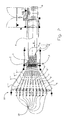
- FIG. 1 shows the side view of a machine 3 for producing wet adhesive labels from a paper web 4 that acts as a material web desired printed image pre-printed paper web 4 is from a supply roll 9 unwound and passes through the machine 3 in the transport direction according to the Arrows R. After unwinding from the supply roll 9, the paper web 4 comes in a buffer station 10 and then becomes an operator overhead 11 out. In a subsequent side regulating station, which is approximately at the level of the head 12, the paper web 4 is finally aligned laterally. Possibly can the printing of the paper web 4 only in the area of Side adjustment station 12 take place.
- the paper web 4 becomes one in the transport direction R.
- Cutting and blanking station 13 fed.
- This station includes one Cutting roller 1, by means of which the wet adhesive labels are rotated out of the Paper web 4 are cut out, and a following in the transport direction R.
- Panel separating roller 2 with the help of which the individual rows of panels assigned wet adhesive labels here in two different tangential directions the depaneling roller 2 on a total of ten transport devices in the form of Suction belt transport devices are delivered, of which only those in Fig. 1 Suction belt transport devices 5 and 6 can be seen (see Fig. 2).
- 1 are especially the suction boxes 14, 15 and the endlessly around drive or Deflection rollers rotating suction belts 16, 17 of the suction belt transport devices 5, 6 to recognize.
- Holding the cut wet adhesive labels on the suction belts 16, 17 takes place in a manner known per se Sucking in ambient air through those located in the suction belts 16, 17 Perforation holes and / or through spaces between several parallel extending suction belts in the suction boxes 14, 15 when the suction belt transport devices 5, 6 each consist of several suction belts.
- the finished wet adhesive labels from the Suction belts 16, 17 delivered to a storage station 18, by means of which they in Cassettes 19 are stored.
- the cassettes 19 are preferably to those that are directly available from bottlers, i.e. without decanting the Wet adhesive labels in other containers, used in their labeling machines can be.
- the printed image applied to the paper web 4 can be seen, which is indicated here by ellipses.
- a total of ten utility rows N 1 , N 2 to N 10 arranged next to one another in the transport direction R are provided.
- the utility separation roller 2 takes over these ten wet adhesive labels from the cutting roller 1 and gives them to a total of ten different transport devices 5, 6, 5 ', 6', 5 ", 6", 5 “', 6"', 5 “” and 6 "” that actively transport the wet adhesive labels away from the depaneling roller 2.
- the wet adhesive labels cut out from the first row of sheets N 1 with respect to the sheet separating roller 2 are in a first tangential direction 7, which can be seen in FIG. 3, on the transport device 5 and the wet adhesive labels cut out from the row of sheets N 2 with respect to the sheet separating roller 2 in a second one in FIG. 3 Tangential direction 8 to be recognized applied to the transport device 6, which is arranged according to FIG. 2 next to the transport device 5.
- the wet adhesive labels are dispensed with regard to the utility rows N 3 , N 4 and the transport devices 5 ', 6', the utility rows N 5 , N 6 and the transport devices 5 ", 6", the utility rows N 7 , N 8 and the transport devices 5 “', 6"', as well as the utility series N 9 , N 10 and the transport devices 5 "", 6 "”.
- the transport devices 5, 5 ', 5 “, 5"' and 5 “” all run in the same, first tangential direction 7, while the transport devices 6, 6 ', 6 “, 6”' and 6 “” all run in the same, second 3, which differs from the first tangential direction 7 according to FIG. 3.
- the wet adhesive labels assigned to the utility rows N 1 , N 3 , N 5 , N 7 and N 9 are thus separated from the utility rows N 2 , N 4 , N 6 ,
- Wet adhesive labels assigned to N 8 and N 10 are spaced vertically, ie upwards and downwards in the direction of view in FIG. 2 or in FIG. 1 in the plane of the drawing.
- the individual wet adhesive labels assigned to the respective utility rows N 1 to N 10 are spaced apart not only vertically but also horizontally, ie up and down in the plane of the drawing in FIG. 2 or in the viewing direction in FIG. 1.
- the necessary space is created not only in the vertical direction but also in the horizontal direction in order to be able to arrange the mechanical structural units for automated storage by means of the storage station 18.
- the transport devices 5, 6, 5 ', 6', 5 “, 6", 5 “', 6"' and 5 “", 6 “” extend from the blanket roller 2 in a fan-like manner, as can be seen in FIG. 2 is.
- the embodiment shown has two superimposed transport levels, with the transport devices 5, 5 ', 5 ", 5"' and 5 “” extending in a fan-like manner in the upper transport level, while in the lower transport plane, the transport devices 6, 6 ', 6 ", 6"' and 6 "” run like a fan.
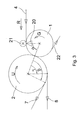
- Fig. 3 the deposition of the invention is shown schematically in a sectional view.
- the printed paper web 4 is fed to the cutting roller 1 rotating counterclockwise according to arrow G.
- the cutting edge 20 corresponding to the desired label geometry is only indicated schematically.
- the cut is made against a counter bar or counter roller 21 that is stationary or rotating as required.
- the suction air control of the cutting roller 1 ensures that the wet adhesive labels of all utility series N 1 to N 10 are held on the cutting roller 1 over a circumferential angle ⁇ . After passing through the circumferential angle ⁇ , the suction air control of the cutting roller 1 releases the wet adhesive labels of all utility rows N 1 to N 10 to the blanking roller 2 rotating clockwise according to arrow U.
- Their suction air control device applies suction air to those suction air openings which hold the wet adhesive labels assigned to the utility series N 1 , N 3 , N 5 , N 7 and N 9 in such a way that they adhere to the circumference of the deposition roller 2 via the circumferential angle ⁇ .
- the delivery takes place in the first tangential direction 7 to the transport devices 5, 5 ', 5 ", 5"' and 5 "".
- the wet adhesive labels assigned to the utility rows N 2 , N 4 , N 6 , N 8 and N 10 are held by the suction air device of the depaneling roller 2 only over the circumferential angle Y on the circumference of the depaneling roller 2, the angle Y being smaller than the angle ⁇ .
- the wet adhesive labels assigned to the benefits N 2 , N 4 , N 6 , N 8 and N 10 are thus dispensed in the second tangential direction 8, that is to say in a plane which runs below the level into which the benefit rows N 1 , N 3 , N 5 , N 7 and N 9 assigned wet adhesive labels.
- the paper web waste 22 is held by the suction device of the cutting roller 1 beyond the circumferential angle ⁇ on the roller circumference and preferably suctioned off in the lower region of the cutting roller 1.
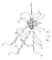
- FIG. 4 shows a perspective view of a further device according to the invention for the separation of panels, a total of three rows of panels N 1 , N 2 and N 3 being provided.
- the wet adhesive labels E, E 'and E "to be produced here have a T-shape as an example.
- the rows of benefits N 1 , N 2 and N 3 interlock laterally due to the minimization of the paper web waste, since the outlines of the labels of the middle row of sheets N 2 are rotated by 180 ° with respect to the outlines of the labels of the rows of sheets N 1 and N 3.
- the suction air openings can be seen in the roll circumferential surface of the sheet separation roller 2.
- suction air channels are on the front end of the cutting roller 2.
- suction air openings and suction air channels are shown in the cutting roller 1.
- the cut is made, as in FIG. 3, against a stationary or rotating counter bar or counter roller 21.
- the cutting roller 2 is covered with a stencil film 23, into which openings according to the geometry of the wet adhesive labels to be produced E , E 'and E "are introduced. This has the effect that, given a given label geometry, only those suction air openings that are required for the specific label geometry develop a suction effect. All other suction air openings in the peripheral surface of the depaneling roller 2 are covered in a simple manner by means of the stencil film 23, which on the one hand avoids annoying leakage air and on the other hand simplifies the suction air control in the depaneling roller 2.
- the control of the suction air device in the blanking roller 2 takes place in such a way that the wet adhesive labels E or E "assigned to the benefit rows N 1 or N 3 are released from the blanking roller 2 only later than the wet adhesive labels E 'assigned to the middle benefit row N 2 the dispensing of the wet adhesive labels E or E "in the first tangential direction 7, which deviates by the angle ⁇ from the second tangential direction 8, in which the wet adhesive labels E 'assigned to the middle row of benefits N 2 are dispensed.
- the wet adhesive labels E, E 'and E are advantageously spaced horizontally by the wet adhesive labels E and E" running apart in the horizontal direction with a spreading angle ⁇ .
Landscapes
- Life Sciences & Earth Sciences (AREA)
- Forests & Forestry (AREA)
- Engineering & Computer Science (AREA)
- Mechanical Engineering (AREA)
- Making Paper Articles (AREA)
- Delivering By Means Of Belts And Rollers (AREA)
- Advancing Webs (AREA)
- Separation, Sorting, Adjustment, Or Bending Of Sheets To Be Conveyed (AREA)
- Processing And Handling Of Plastics And Other Materials For Molding In General (AREA)
Applications Claiming Priority (2)
| Application Number | Priority Date | Filing Date | Title |
|---|---|---|---|
| DE10300234 | 2003-01-08 | ||
| DE10300234A DE10300234B3 (de) | 2003-01-08 | 2003-01-08 | Vorrichtung und Verfahren zur Nutzentrennung in einer Maschine zur Herstellung von aus einer Materialbahn ausgeschnittenen Flachmaterialstücken |
Publications (3)
| Publication Number | Publication Date |
|---|---|
| EP1437202A2 true EP1437202A2 (fr) | 2004-07-14 |
| EP1437202A3 EP1437202A3 (fr) | 2005-05-25 |
| EP1437202B1 EP1437202B1 (fr) | 2007-03-07 |
Family
ID=32478161
Family Applications (1)
| Application Number | Title | Priority Date | Filing Date |
|---|---|---|---|
| EP03029761A Expired - Lifetime EP1437202B1 (fr) | 2003-01-08 | 2003-12-23 | Dispositif et procédé pour la séparation de poses dans une machine pour la production d'éléments plans découpés à partir d'une bande |
Country Status (5)
| Country | Link |
|---|---|
| US (1) | US20040198577A1 (fr) |
| EP (1) | EP1437202B1 (fr) |
| AT (1) | ATE355941T1 (fr) |
| DE (2) | DE10300234B3 (fr) |
| ES (1) | ES2283710T3 (fr) |
Cited By (1)
| Publication number | Priority date | Publication date | Assignee | Title |
|---|---|---|---|---|
| EP3181311A1 (fr) * | 2015-12-14 | 2017-06-21 | Harro Höfliger Verpackungsmaschinen GmbH | Dispositif de détachement de portions d'une nappe de tissus |
Families Citing this family (27)
| Publication number | Priority date | Publication date | Assignee | Title |
|---|---|---|---|---|
| DE102007003592B3 (de) | 2007-01-24 | 2008-07-03 | WINKLER + DüNNEBIER AG | Saugwalze zum Transportieren von Flachmaterialzuschnitten |
| EP3050684B1 (fr) | 2011-11-10 | 2017-08-16 | Packsize LLC | Machine de conversion élevée avec un guide de sortie |
| US10093438B2 (en) | 2014-12-29 | 2018-10-09 | Packsize Llc | Converting machine |
| CN108472825B (zh) | 2015-11-23 | 2020-03-24 | 柯尼格及包尔公开股份有限公司 | 用于处理基材的装置和方法 |
| DE102016223223A1 (de) | 2015-11-23 | 2017-05-24 | Koenig & Bauer Ag | Vorrichtung zum Behandeln von Substraten |
| CN108472826B (zh) | 2015-11-23 | 2020-03-27 | 柯尼格及包尔公开股份有限公司 | 用于处理基材的装置 |
| EP3380329B1 (fr) | 2015-11-23 | 2019-09-04 | Koenig & Bauer AG | Procédé et dispositif comprenant des modules et des dispositifs de découpe pour substrats en forme de feuille |
| DE102016223225A1 (de) | 2015-11-23 | 2017-05-24 | Koenig & Bauer Ag | Vorrichtung zum Behandeln von Substraten |
| DE102015223107B4 (de) * | 2015-11-23 | 2023-05-25 | Koenig & Bauer Ag | Vorrichtung zum Behandeln von Substraten |
| DE102016226167A1 (de) | 2016-05-30 | 2017-11-30 | Koenig & Bauer Ag | Vorrichtung und Verfahren zum Behandeln von Substraten |
| US11214032B2 (en) * | 2016-06-16 | 2022-01-04 | Packsize Llc | Box template production system and method |
| US10850469B2 (en) | 2016-06-16 | 2020-12-01 | Packsize Llc | Box forming machine |
| US10351380B2 (en) | 2016-10-14 | 2019-07-16 | A.G. Stacker Inc. | Diverter conveyor |
| US11242214B2 (en) | 2017-01-18 | 2022-02-08 | Packsize Llc | Converting machine with fold sensing mechanism |
| SE541921C2 (en) | 2017-03-06 | 2020-01-07 | Packsize Llc | A box erecting method and system |
| DE102017204598B4 (de) | 2017-03-20 | 2021-06-10 | Koenig & Bauer Ag | Vorrichtung zum Behandeln von Substraten |
| DE102017204596B4 (de) | 2017-03-20 | 2020-05-14 | Koenig & Bauer Ag | Werkzeug und Positionierverfahren |
| DE102017204595B4 (de) | 2017-03-20 | 2021-06-10 | Koenig & Bauer Ag | Vorrichtung zum Behandeln von Substraten |
| SE1750727A1 (sv) | 2017-06-08 | 2018-10-09 | Packsize Llc | Tool head positioning mechanism for a converting machine, and method for positioning a plurality of tool heads in a converting machine |
| US11173685B2 (en) | 2017-12-18 | 2021-11-16 | Packsize Llc | Method for erecting boxes |
| US11305903B2 (en) | 2018-04-05 | 2022-04-19 | Avercon BVBA | Box template folding process and mechanisms |
| US11247427B2 (en) | 2018-04-05 | 2022-02-15 | Avercon BVBA | Packaging machine infeed, separation, and creasing mechanisms |
| DE112019003075T5 (de) | 2018-06-21 | 2021-03-25 | Packsize Llc | Verpackungsvorrichtung und systeme |
| SE543046C2 (en) | 2018-09-05 | 2020-09-29 | Packsize Llc | A box erecting method and system |
| DE102018219715B3 (de) | 2018-11-16 | 2020-01-16 | Koenig & Bauer Ag | Vorrichtung und eine bogenverarbeitende Maschine zum Behandeln von Substraten |
| DE102018219712B4 (de) | 2018-11-16 | 2021-08-05 | Koenig & Bauer Ag | Vorrichtung zum Behandeln von Substraten |
| US11752725B2 (en) | 2019-01-07 | 2023-09-12 | Packsize Llc | Box erecting machine |
Citations (1)
| Publication number | Priority date | Publication date | Assignee | Title |
|---|---|---|---|---|
| DE19841834A1 (de) | 1998-09-12 | 2000-03-16 | Winkler & Duennebier Ag | Drehbare Messerwalze |
Family Cites Families (18)
| Publication number | Priority date | Publication date | Assignee | Title |
|---|---|---|---|---|
| US3575331A (en) * | 1969-11-10 | 1971-04-20 | Kopper Co Inc | Web-guiding apparatus |
| US3754647A (en) * | 1972-02-22 | 1973-08-28 | Owens Illinois Inc | Apparatus and method for removing selected sheets from the lower bridge of a corrugated paper board manufacturing machine |
| US4080856A (en) * | 1975-09-23 | 1978-03-28 | E. I. Du Pont De Nemours And Company | Rotary web chopper |
| FR2392916A1 (fr) * | 1977-05-31 | 1978-12-29 | Chambre Imprimerie Claude | Dispositif pour effectuer des decoupages dans une bande de materiau defilant en continu |
| DE2725546A1 (de) * | 1977-06-07 | 1978-12-21 | Womako Masch Konstr | Vorrichtung zum umlenken von papierboegen |
| US4190241A (en) * | 1978-05-01 | 1980-02-26 | Kimberly-Clark Corporation | Apparatus for converting paper rolls into stacks of individual folded paper sheets |
| DE3131687A1 (de) * | 1981-08-11 | 1983-03-03 | Focke & Co, 2810 Verden | "verpackungs-vorrichtung zum herstellen von zuschnitten und zufuehren derselben in einer verpackungsstation" |
| DE4000078A1 (de) * | 1990-01-03 | 1991-07-04 | Winkler Duennebier Kg Masch | Messerwalze |
| JP3320852B2 (ja) * | 1993-08-02 | 2002-09-03 | 株式会社名南製作所 | シート状物品の振分け装置 |
| US5566600A (en) * | 1994-10-11 | 1996-10-22 | Formax, Inc. | Conveyor/classifier system for versatile hi-speed food loaf slicing machine |
| US5575187A (en) * | 1994-11-14 | 1996-11-19 | R. A. Jones & Co. Inc. | Variable count direct deposit knife |
| EP0951426B1 (fr) * | 1996-12-20 | 2002-04-03 | Interket Trykkeri A/S | Empileuse d'etiquettes pour appareil rotatif |
| CA2205622A1 (fr) * | 1997-05-16 | 1998-11-16 | Allan R. Prittie | Appareil pour enlever des fenetres decoupees d'une bande de carton |
| DE19723749A1 (de) * | 1997-06-06 | 1998-12-10 | Koenig & Bauer Albert Ag | Verfahren und Vorrichtung zum Quertrennen von laufenden Bedruckstoffbahnen |
| DE19925612B4 (de) * | 1999-06-04 | 2007-10-31 | WINKLER + DüNNEBIER AG | Drehbare Messerwalze mit Folienmesser |
| JP2002205295A (ja) * | 2001-01-11 | 2002-07-23 | Fuji Photo Film Co Ltd | ウェブ切断装置及びウェブ切断方法 |
| DE10114064A1 (de) * | 2001-03-22 | 2002-09-26 | Heidelberger Druckmasch Ag | Einrichtung zur Auslage flächiger Exemplare |
| DE10156664B4 (de) * | 2001-11-17 | 2006-02-23 | Mende, Bernd, Dipl.-Ing. | Vorrichtung zum rotierenden Stanzen von Nutzen aus Einzelbögen |
-
2003
- 2003-01-08 DE DE10300234A patent/DE10300234B3/de not_active Expired - Fee Related
- 2003-12-23 AT AT03029761T patent/ATE355941T1/de not_active IP Right Cessation
- 2003-12-23 EP EP03029761A patent/EP1437202B1/fr not_active Expired - Lifetime
- 2003-12-23 DE DE50306737T patent/DE50306737D1/de not_active Expired - Fee Related
- 2003-12-23 ES ES03029761T patent/ES2283710T3/es not_active Expired - Lifetime
-
2004
- 2004-01-08 US US10/754,086 patent/US20040198577A1/en not_active Abandoned
Patent Citations (1)
| Publication number | Priority date | Publication date | Assignee | Title |
|---|---|---|---|---|
| DE19841834A1 (de) | 1998-09-12 | 2000-03-16 | Winkler & Duennebier Ag | Drehbare Messerwalze |
Cited By (1)
| Publication number | Priority date | Publication date | Assignee | Title |
|---|---|---|---|---|
| EP3181311A1 (fr) * | 2015-12-14 | 2017-06-21 | Harro Höfliger Verpackungsmaschinen GmbH | Dispositif de détachement de portions d'une nappe de tissus |
Also Published As
| Publication number | Publication date |
|---|---|
| DE50306737D1 (de) | 2007-04-19 |
| EP1437202B1 (fr) | 2007-03-07 |
| ATE355941T1 (de) | 2007-03-15 |
| ES2283710T3 (es) | 2007-11-01 |
| EP1437202A3 (fr) | 2005-05-25 |
| DE10300234B3 (de) | 2004-07-15 |
| US20040198577A1 (en) | 2004-10-07 |
Similar Documents
| Publication | Publication Date | Title |
|---|---|---|
| DE10300234B3 (de) | Vorrichtung und Verfahren zur Nutzentrennung in einer Maschine zur Herstellung von aus einer Materialbahn ausgeschnittenen Flachmaterialstücken | |
| DE3041050C2 (de) | Verfahren zur Herstellung von kunststoffbeschichteten Flüssigkeitsverpackungen | |
| EP1072551A2 (fr) | Ensemble d'une machine de pliage dans une machine à imprimer rotative pour journaux | |
| DE102012019992A1 (de) | Vorrichtung für eine Flachbettstanze und Verfahren zum Zuführen einer Bedruckstoffbahn | |
| WO2021233592A1 (fr) | Machine de traitement de feuilles dotée d'au moins un système de transport de transfert et procédé de transport de feuilles dans une machine de traitement de feuilles | |
| EP0288814A1 (fr) | Dispositif pour subdiviser une bande de papier sans fin avec un plissement en accordéon | |
| DE102012002110A1 (de) | Vorrichtung zur Stanzbearbeitung von bogenförmigen Substraten | |
| EP0697989B1 (fr) | Dispositif permettant de transferer et d'empiler des feuilles | |
| EP0755356B1 (fr) | Procede et dispositif permettant de reunir et de traiter des bandes de papier | |
| WO2021083675A1 (fr) | Machine de traitement de feuilles avec au moins un dispositif de stockage de feuilles, et procédé de stockage de feuilles | |
| DE10300233B3 (de) | Vorrichtung und Verfahren zur Ablage von aus einer Materialbahn ausgeschnittenen Flachmaterialstücken | |
| DE4314756C2 (de) | Vorrichtung zum Schuppen und Ablegen von Bogen auf einen Stapel | |
| EP1839858A2 (fr) | Appareil de pliage d'une machine d'impression et procédé destiné au fonctionnement de celle-ci | |
| DE102021131591B3 (de) | Stanzaggregat mit einer Vorrichtung zum Wechseln eines Stanzzylinders sowie Verfahren zum Wechseln eines Stanzzylinders | |
| DE102020113373B3 (de) | Bogenbearbeitungsmaschine | |
| DE102022100960B3 (de) | Stanzaggregat mit einer Vorrichtung zum Wechseln eines Stanzzylinders sowie Verfahren zum Wechseln eines Stanzzylinders | |
| WO2009015773A1 (fr) | Procédé de réalisation de pièces de matériau plat découpées, formant des flancs, à partir de feuilles de matériau plat séparées et presse de découpe rotative pour la mise en oeuvre dudit procédé | |
| EP0505533B1 (fr) | Dispositif d'elimination de bandes residuelles | |
| DE102019108874B3 (de) | Transportvorrichtung für ein bogenförmiges Substrat und Verfahren zum Transport zumindest eines bogenförmigen Substrats | |
| DE102022100962B3 (de) | Stanzaggregat sowie Verfahren zum Verstellen einer Transporteinrichtung | |
| DE102019128981B4 (de) | Bogenbearbeitungsmaschine mit einem als Kettengreifersystem ausgebildeten Transportsystem und ein Verfahren zum Verstellen eines Kettengreiferöffners | |
| DE19605339C1 (de) | Vorrichtung zum Schneiden einer Endlospapierbahn | |
| EP1615773A2 (fr) | Procede permettant de generer un produit d'impression, dispositif de post-traitement, et systeme servant a generer des produits d'impression | |
| DE102004023222B3 (de) | Vorrichtung und Verfahren zum wahlweisen Einziehen eines Zuschnitts aus einem Stapel mehrerer Zuschnitte oder Übernehmen eines Zuschnitts von einer Trennschneideeinrichtung | |
| DE102016200481B4 (de) | Vorrichtung und Verfahren zur Be- und/oder Verarbeitung bahnförmigen Bedruckstoffs |
Legal Events
| Date | Code | Title | Description |
|---|---|---|---|
| PUAI | Public reference made under article 153(3) epc to a published international application that has entered the european phase |
Free format text: ORIGINAL CODE: 0009012 |
|
| AK | Designated contracting states |
Kind code of ref document: A2 Designated state(s): AT BE BG CH CY CZ DE DK EE ES FI FR GB GR HU IE IT LI LU MC NL PT RO SE SI SK TR |
|
| AX | Request for extension of the european patent |
Extension state: AL LT LV MK |
|
| PUAL | Search report despatched |
Free format text: ORIGINAL CODE: 0009013 |
|
| AK | Designated contracting states |
Kind code of ref document: A3 Designated state(s): AT BE BG CH CY CZ DE DK EE ES FI FR GB GR HU IE IT LI LU MC NL PT RO SE SI SK TR |
|
| AX | Request for extension of the european patent |
Extension state: AL LT LV MK |
|
| RIC1 | Information provided on ipc code assigned before grant |
Ipc: 7B 65H 29/24 B Ipc: 7B 26D 7/18 A |
|
| 17P | Request for examination filed |
Effective date: 20051111 |
|
| AKX | Designation fees paid |
Designated state(s): AT BE BG CH CY CZ DE DK EE ES FI FR GB GR HU IE IT LI LU MC NL PT RO SE SI SK TR |
|
| GRAP | Despatch of communication of intention to grant a patent |
Free format text: ORIGINAL CODE: EPIDOSNIGR1 |
|
| GRAS | Grant fee paid |
Free format text: ORIGINAL CODE: EPIDOSNIGR3 |
|
| GRAA | (expected) grant |
Free format text: ORIGINAL CODE: 0009210 |
|
| AK | Designated contracting states |
Kind code of ref document: B1 Designated state(s): AT BE BG CH CY CZ DE DK EE ES FI FR GB GR HU IE IT LI LU MC NL PT RO SE SI SK TR |
|
| PG25 | Lapsed in a contracting state [announced via postgrant information from national office to epo] |
Ref country code: NL Free format text: LAPSE BECAUSE OF FAILURE TO SUBMIT A TRANSLATION OF THE DESCRIPTION OR TO PAY THE FEE WITHIN THE PRESCRIBED TIME-LIMIT Effective date: 20070307 Ref country code: SI Free format text: LAPSE BECAUSE OF FAILURE TO SUBMIT A TRANSLATION OF THE DESCRIPTION OR TO PAY THE FEE WITHIN THE PRESCRIBED TIME-LIMIT Effective date: 20070307 Ref country code: IE Free format text: LAPSE BECAUSE OF FAILURE TO SUBMIT A TRANSLATION OF THE DESCRIPTION OR TO PAY THE FEE WITHIN THE PRESCRIBED TIME-LIMIT Effective date: 20070307 Ref country code: FI Free format text: LAPSE BECAUSE OF FAILURE TO SUBMIT A TRANSLATION OF THE DESCRIPTION OR TO PAY THE FEE WITHIN THE PRESCRIBED TIME-LIMIT Effective date: 20070307 |
|
| REG | Reference to a national code |
Ref country code: GB Ref legal event code: FG4D Free format text: NOT ENGLISH |
|
| REG | Reference to a national code |
Ref country code: CH Ref legal event code: EP |
|
| REF | Corresponds to: |
Ref document number: 50306737 Country of ref document: DE Date of ref document: 20070419 Kind code of ref document: P |
|
| REG | Reference to a national code |
Ref country code: IE Ref legal event code: FG4D Free format text: LANGUAGE OF EP DOCUMENT: GERMAN |
|
| PG25 | Lapsed in a contracting state [announced via postgrant information from national office to epo] |
Ref country code: SE Free format text: LAPSE BECAUSE OF FAILURE TO SUBMIT A TRANSLATION OF THE DESCRIPTION OR TO PAY THE FEE WITHIN THE PRESCRIBED TIME-LIMIT Effective date: 20070607 |
|
| PG25 | Lapsed in a contracting state [announced via postgrant information from national office to epo] |
Ref country code: PT Free format text: LAPSE BECAUSE OF FAILURE TO SUBMIT A TRANSLATION OF THE DESCRIPTION OR TO PAY THE FEE WITHIN THE PRESCRIBED TIME-LIMIT Effective date: 20070807 |
|
| NLV1 | Nl: lapsed or annulled due to failure to fulfill the requirements of art. 29p and 29m of the patents act | ||
| ET | Fr: translation filed | ||
| GBV | Gb: ep patent (uk) treated as always having been void in accordance with gb section 77(7)/1977 [no translation filed] |
Effective date: 20070307 |
|
| REG | Reference to a national code |
Ref country code: IE Ref legal event code: FD4D |
|
| REG | Reference to a national code |
Ref country code: ES Ref legal event code: FG2A Ref document number: 2283710 Country of ref document: ES Kind code of ref document: T3 |
|
| PG25 | Lapsed in a contracting state [announced via postgrant information from national office to epo] |
Ref country code: GB Free format text: LAPSE BECAUSE OF FAILURE TO SUBMIT A TRANSLATION OF THE DESCRIPTION OR TO PAY THE FEE WITHIN THE PRESCRIBED TIME-LIMIT Effective date: 20070307 Ref country code: SK Free format text: LAPSE BECAUSE OF FAILURE TO SUBMIT A TRANSLATION OF THE DESCRIPTION OR TO PAY THE FEE WITHIN THE PRESCRIBED TIME-LIMIT Effective date: 20070307 |
|
| PG25 | Lapsed in a contracting state [announced via postgrant information from national office to epo] |
Ref country code: RO Free format text: LAPSE BECAUSE OF FAILURE TO SUBMIT A TRANSLATION OF THE DESCRIPTION OR TO PAY THE FEE WITHIN THE PRESCRIBED TIME-LIMIT Effective date: 20070307 Ref country code: CZ Free format text: LAPSE BECAUSE OF FAILURE TO SUBMIT A TRANSLATION OF THE DESCRIPTION OR TO PAY THE FEE WITHIN THE PRESCRIBED TIME-LIMIT Effective date: 20070307 |
|
| PLBE | No opposition filed within time limit |
Free format text: ORIGINAL CODE: 0009261 |
|
| STAA | Information on the status of an ep patent application or granted ep patent |
Free format text: STATUS: NO OPPOSITION FILED WITHIN TIME LIMIT |
|
| PG25 | Lapsed in a contracting state [announced via postgrant information from national office to epo] |
Ref country code: DK Free format text: LAPSE BECAUSE OF FAILURE TO SUBMIT A TRANSLATION OF THE DESCRIPTION OR TO PAY THE FEE WITHIN THE PRESCRIBED TIME-LIMIT Effective date: 20070307 |
|
| PGFP | Annual fee paid to national office [announced via postgrant information from national office to epo] |
Ref country code: ES Payment date: 20071220 Year of fee payment: 5 |
|
| 26N | No opposition filed |
Effective date: 20071210 |
|
| PGFP | Annual fee paid to national office [announced via postgrant information from national office to epo] |
Ref country code: IT Payment date: 20071220 Year of fee payment: 5 Ref country code: CH Payment date: 20071219 Year of fee payment: 5 |
|
| PGFP | Annual fee paid to national office [announced via postgrant information from national office to epo] |
Ref country code: BE Payment date: 20071219 Year of fee payment: 5 |
|
| PG25 | Lapsed in a contracting state [announced via postgrant information from national office to epo] |
Ref country code: GR Free format text: LAPSE BECAUSE OF FAILURE TO SUBMIT A TRANSLATION OF THE DESCRIPTION OR TO PAY THE FEE WITHIN THE PRESCRIBED TIME-LIMIT Effective date: 20070608 |
|
| PGFP | Annual fee paid to national office [announced via postgrant information from national office to epo] |
Ref country code: DE Payment date: 20080221 Year of fee payment: 5 |
|
| PG25 | Lapsed in a contracting state [announced via postgrant information from national office to epo] |
Ref country code: MC Free format text: LAPSE BECAUSE OF NON-PAYMENT OF DUE FEES Effective date: 20071231 |
|
| PGFP | Annual fee paid to national office [announced via postgrant information from national office to epo] |
Ref country code: FR Payment date: 20071214 Year of fee payment: 5 |
|
| PG25 | Lapsed in a contracting state [announced via postgrant information from national office to epo] |
Ref country code: EE Free format text: LAPSE BECAUSE OF FAILURE TO SUBMIT A TRANSLATION OF THE DESCRIPTION OR TO PAY THE FEE WITHIN THE PRESCRIBED TIME-LIMIT Effective date: 20070307 |
|
| PG25 | Lapsed in a contracting state [announced via postgrant information from national office to epo] |
Ref country code: AT Free format text: LAPSE BECAUSE OF NON-PAYMENT OF DUE FEES Effective date: 20071223 |
|
| BERE | Be: lapsed |
Owner name: WINKLER + DUNNEBIER A.G. Effective date: 20081231 |
|
| PG25 | Lapsed in a contracting state [announced via postgrant information from national office to epo] |
Ref country code: CY Free format text: LAPSE BECAUSE OF FAILURE TO SUBMIT A TRANSLATION OF THE DESCRIPTION OR TO PAY THE FEE WITHIN THE PRESCRIBED TIME-LIMIT Effective date: 20070307 |
|
| REG | Reference to a national code |
Ref country code: CH Ref legal event code: PL |
|
| PG25 | Lapsed in a contracting state [announced via postgrant information from national office to epo] |
Ref country code: BG Free format text: LAPSE BECAUSE OF FAILURE TO SUBMIT A TRANSLATION OF THE DESCRIPTION OR TO PAY THE FEE WITHIN THE PRESCRIBED TIME-LIMIT Effective date: 20070607 Ref country code: LU Free format text: LAPSE BECAUSE OF NON-PAYMENT OF DUE FEES Effective date: 20071223 |
|
| PG25 | Lapsed in a contracting state [announced via postgrant information from national office to epo] |
Ref country code: BE Free format text: LAPSE BECAUSE OF NON-PAYMENT OF DUE FEES Effective date: 20081231 Ref country code: TR Free format text: LAPSE BECAUSE OF FAILURE TO SUBMIT A TRANSLATION OF THE DESCRIPTION OR TO PAY THE FEE WITHIN THE PRESCRIBED TIME-LIMIT Effective date: 20070307 Ref country code: HU Free format text: LAPSE BECAUSE OF FAILURE TO SUBMIT A TRANSLATION OF THE DESCRIPTION OR TO PAY THE FEE WITHIN THE PRESCRIBED TIME-LIMIT Effective date: 20070908 |
|
| REG | Reference to a national code |
Ref country code: FR Ref legal event code: ST Effective date: 20090831 |
|
| PG25 | Lapsed in a contracting state [announced via postgrant information from national office to epo] |
Ref country code: CH Free format text: LAPSE BECAUSE OF NON-PAYMENT OF DUE FEES Effective date: 20081231 Ref country code: LI Free format text: LAPSE BECAUSE OF NON-PAYMENT OF DUE FEES Effective date: 20081231 Ref country code: DE Free format text: LAPSE BECAUSE OF NON-PAYMENT OF DUE FEES Effective date: 20090701 |
|
| REG | Reference to a national code |
Ref country code: ES Ref legal event code: FD2A Effective date: 20081224 |
|
| PG25 | Lapsed in a contracting state [announced via postgrant information from national office to epo] |
Ref country code: ES Free format text: LAPSE BECAUSE OF NON-PAYMENT OF DUE FEES Effective date: 20081224 Ref country code: FR Free format text: LAPSE BECAUSE OF NON-PAYMENT OF DUE FEES Effective date: 20081231 |
|
| PG25 | Lapsed in a contracting state [announced via postgrant information from national office to epo] |
Ref country code: IT Free format text: LAPSE BECAUSE OF NON-PAYMENT OF DUE FEES Effective date: 20081223 |