EP1436134B1 - Vorrichtung zum kühlen von halsenden von geformten gegenständen nach dem formen - Google Patents
Vorrichtung zum kühlen von halsenden von geformten gegenständen nach dem formen Download PDFInfo
- Publication number
- EP1436134B1 EP1436134B1 EP02742586A EP02742586A EP1436134B1 EP 1436134 B1 EP1436134 B1 EP 1436134B1 EP 02742586 A EP02742586 A EP 02742586A EP 02742586 A EP02742586 A EP 02742586A EP 1436134 B1 EP1436134 B1 EP 1436134B1
- Authority
- EP
- European Patent Office
- Prior art keywords
- cooling
- preform
- coolant
- molded article
- cooling apparatus
- Prior art date
- Legal status (The legal status is an assumption and is not a legal conclusion. Google has not performed a legal analysis and makes no representation as to the accuracy of the status listed.)
- Expired - Lifetime
Links
- 238000001816 cooling Methods 0.000 title claims abstract description 178
- 239000002826 coolant Substances 0.000 claims description 58
- 239000006185 dispersion Substances 0.000 claims description 29
- 238000000465 moulding Methods 0.000 claims description 25
- 239000012530 fluid Substances 0.000 claims description 7
- 238000007599 discharging Methods 0.000 claims description 5
- 230000001154 acute effect Effects 0.000 claims 1
- 239000012809 cooling fluid Substances 0.000 abstract description 13
- 238000002347 injection Methods 0.000 abstract description 5
- 239000007924 injection Substances 0.000 abstract description 5
- 238000000034 method Methods 0.000 abstract description 5
- 239000003570 air Substances 0.000 description 56
- 238000001746 injection moulding Methods 0.000 description 9
- 239000012768 molten material Substances 0.000 description 8
- 238000012546 transfer Methods 0.000 description 8
- 230000008901 benefit Effects 0.000 description 7
- 239000012080 ambient air Substances 0.000 description 5
- 238000009826 distribution Methods 0.000 description 4
- 230000002829 reductive effect Effects 0.000 description 4
- 230000003750 conditioning effect Effects 0.000 description 3
- 239000000463 material Substances 0.000 description 3
- 230000007246 mechanism Effects 0.000 description 3
- 230000000717 retained effect Effects 0.000 description 3
- CURLTUGMZLYLDI-UHFFFAOYSA-N Carbon dioxide Chemical compound O=C=O CURLTUGMZLYLDI-UHFFFAOYSA-N 0.000 description 2
- 101150055539 HADH gene Proteins 0.000 description 2
- 238000000071 blow moulding Methods 0.000 description 2
- 239000000498 cooling water Substances 0.000 description 2
- 230000007812 deficiency Effects 0.000 description 2
- 238000013461 design Methods 0.000 description 2
- 230000000694 effects Effects 0.000 description 2
- 230000036961 partial effect Effects 0.000 description 2
- 239000004033 plastic Substances 0.000 description 2
- 229920003023 plastic Polymers 0.000 description 2
- 230000008569 process Effects 0.000 description 2
- 239000007787 solid Substances 0.000 description 2
- 229920000219 Ethylene vinyl alcohol Polymers 0.000 description 1
- 239000004743 Polypropylene Substances 0.000 description 1
- 230000002411 adverse Effects 0.000 description 1
- 230000004888 barrier function Effects 0.000 description 1
- 238000007664 blowing Methods 0.000 description 1
- 229910002092 carbon dioxide Inorganic materials 0.000 description 1
- 239000001569 carbon dioxide Substances 0.000 description 1
- 229910010293 ceramic material Inorganic materials 0.000 description 1
- 230000008859 change Effects 0.000 description 1
- 238000004891 communication Methods 0.000 description 1
- 230000001143 conditioned effect Effects 0.000 description 1
- 239000000110 cooling liquid Substances 0.000 description 1
- 238000002425 crystallisation Methods 0.000 description 1
- 230000008025 crystallization Effects 0.000 description 1
- UFRKOOWSQGXVKV-UHFFFAOYSA-N ethene;ethenol Chemical compound C=C.OC=C UFRKOOWSQGXVKV-UHFFFAOYSA-N 0.000 description 1
- 239000004715 ethylene vinyl alcohol Substances 0.000 description 1
- 238000010438 heat treatment Methods 0.000 description 1
- 230000000977 initiatory effect Effects 0.000 description 1
- 239000007788 liquid Substances 0.000 description 1
- 230000014759 maintenance of location Effects 0.000 description 1
- 239000000155 melt Substances 0.000 description 1
- 239000002184 metal Substances 0.000 description 1
- 230000004048 modification Effects 0.000 description 1
- 238000012986 modification Methods 0.000 description 1
- 238000013021 overheating Methods 0.000 description 1
- -1 polypropylene Polymers 0.000 description 1
- 229920001155 polypropylene Polymers 0.000 description 1
- 230000001681 protective effect Effects 0.000 description 1
- 230000009467 reduction Effects 0.000 description 1
- 230000000284 resting effect Effects 0.000 description 1
- 239000000523 sample Substances 0.000 description 1
- 238000007789 sealing Methods 0.000 description 1
- 239000011343 solid material Substances 0.000 description 1
- 238000004781 supercooling Methods 0.000 description 1
- 238000009827 uniform distribution Methods 0.000 description 1
- 238000010792 warming Methods 0.000 description 1
- XLYOFNOQVPJJNP-UHFFFAOYSA-N water Substances O XLYOFNOQVPJJNP-UHFFFAOYSA-N 0.000 description 1
Images


Classifications
-
- B—PERFORMING OPERATIONS; TRANSPORTING
- B29—WORKING OF PLASTICS; WORKING OF SUBSTANCES IN A PLASTIC STATE IN GENERAL
- B29C—SHAPING OR JOINING OF PLASTICS; SHAPING OF MATERIAL IN A PLASTIC STATE, NOT OTHERWISE PROVIDED FOR; AFTER-TREATMENT OF THE SHAPED PRODUCTS, e.g. REPAIRING
- B29C45/00—Injection moulding, i.e. forcing the required volume of moulding material through a nozzle into a closed mould; Apparatus therefor
- B29C45/17—Component parts, details or accessories; Auxiliary operations
- B29C45/72—Heating or cooling
- B29C45/7207—Heating or cooling of the moulded articles
- B29C2045/7264—Cooling or heating the neck portion of preforms
-
- B—PERFORMING OPERATIONS; TRANSPORTING
- B29—WORKING OF PLASTICS; WORKING OF SUBSTANCES IN A PLASTIC STATE IN GENERAL
- B29K—INDEXING SCHEME ASSOCIATED WITH SUBCLASSES B29B, B29C OR B29D, RELATING TO MOULDING MATERIALS OR TO MATERIALS FOR MOULDS, REINFORCEMENTS, FILLERS OR PREFORMED PARTS, e.g. INSERTS
- B29K2105/00—Condition, form or state of moulded material or of the material to be shaped
- B29K2105/25—Solid
- B29K2105/253—Preform
-
- Y—GENERAL TAGGING OF NEW TECHNOLOGICAL DEVELOPMENTS; GENERAL TAGGING OF CROSS-SECTIONAL TECHNOLOGIES SPANNING OVER SEVERAL SECTIONS OF THE IPC; TECHNICAL SUBJECTS COVERED BY FORMER USPC CROSS-REFERENCE ART COLLECTIONS [XRACs] AND DIGESTS
- Y10—TECHNICAL SUBJECTS COVERED BY FORMER USPC
- Y10S—TECHNICAL SUBJECTS COVERED BY FORMER USPC CROSS-REFERENCE ART COLLECTIONS [XRACs] AND DIGESTS
- Y10S264/00—Plastic and nonmetallic article shaping or treating: processes
- Y10S264/907—Direct application of fluid pressure differential to shape, reshape, i.e. distort, or sustain an article or preform and crystallizing of nonstretched or molecularly unoriented portion thereof
- Y10S264/908—Crystallizing of neck portion of hollow article or hollow preform
Definitions
- the present invention broadly relates to injection-molding machines and, in particular, to the manner in which a molded article from an injection-molding machine is cooled.
- Injection-molding machines are very well known and there are many ways of cooling a preform created by such machines.
- the following references all disclose apparatus and methods for cooling such preforms.
- United States patent 4,449,913 to Krishnakumar et al describes a turret-molding machine in which the preforms are first cooled to a set or crystallized state in the injection mold before they are removed from the mold cavity.
- the preforms When set, the preforms are rotated to a cooling position where nozzles 54 direct coolant onto the tip of the preform so that the preform will cool from its tip towards the neck portion of the preform.
- After cooling the preform is rotated to a conditioning mold 46 for final cooling of the preform.
- the cores 26 are supplied with coolant so as to assure cooling of the preforms radially outwardly. Additional cooling to the exterior of the preforms is provided by the coolant lines 74, which open generally radially into the conditioning cavities 48.
- the threaded neck finish portion of the preform is not directly exposed to any exterior cooling and is only exposed to interior cooling from the coolant flowing through chamber 62 into the cores 26.
- United States patent 4,472,131 to Ryder describes a preform molding machine in which alternating rows of molding and supercooling cavities are mounted on the molding plate so that as a row of preforms is molded an alternate row of preforms is supercooled.
- the patent does not provide a coolant flow directly to the neck portion of the preform either while the preform remains in contact with the molding surface or after removal from the molding surface.
- United States Reissue Patent 33,237 to Delfer, III describes a preform molding system in which the carrier plate has a number of receiving cavities which is a multiple of the number of mold cavities in the injection-molding machine. This enables the preforms to be held in the carrier plate for a multiple of molding cycles and to be fully cooled in the carrier plate.
- the patent does not provide means for directly cooling the neck portion of a preform.
- United States Patents 5,114,327, 5,338,172 and 5,514,309 to Williamson et al describe an apparatus that comprises an external holder tube and an inner probe that combine in assembly to enclose the preform such that a cooling fluid, such as liquid carbon dioxide, is circulated over both the inner and outer surfaces of the preform including the neck finish portion.
- the preform is enclosed in a closed circuit environment so that the cooling fluid may be recovered.
- the patents do not disclose means for creating a specific flow direction or distribution of the cooling media in the neck finish portion so as to promote a balanced thermal transfer of heat from the preform.
- United States Patent 5,232,715 to Fukar describes cooling a preform wherein cooling air is provided to the interior and exterior of the preform simultaneously. The external cooling air flows over the tip of the preform towards the neck portion, which is held in a neck mold. There is no direct cooling of the neck portion.
- United States Patent 5,728,409 to Schad et al describes a turret injection-molding machine in which preforms remain on the cooled mold core for an extended period of time after molding while cool air is blown over their exterior finishes. These machines have mold inserts for forming the neck finish portion of the preform and are water-cooled. The inserts remain in their molding position surrounding the neck finish portion of the molded preforms during subsequent turret positions where air-cooling is being directed onto the preform's exterior surface.
- the patent does not provide any means for controllably cooling the neck finish portion of the preform after the preform leaves the molding surface.
- United States Patent 6,059,557 to Ing et al describes a turret-molding machine in which cooling tubes cool the exterior of the preform. The neck portion of the preform is not directly cooled.
- the invention provides a two-turret machine with a cycle time equivalent to that of the prior art four-turret machine.
- United States Patent 6,095,788 to Dirk van Manen et al describes a preform cooling arrangement where cooling tubes are located adjacent molding cavities so that during each cycle a preform is molded in each molding cavity and another preform is cooled in an adjacent cooling cavity. During the entire cycle the neck portion of the preform is held in a neck ring. The arrangement reduces the stroke of the machine but does not provide any direct cooling of the neck portion of the preform.
- United States Patent 6,223,541 to Farrag describes a post-mold preform cooling station in which coolant is provide through a tube 17 to the interior surface of the preform and flows over the inner surface of the preform in a direction from the tip to the neck of the preform.
- Japanese Patent Publication 7-171888 to Hirowatari describes a preform cooling apparatus where cooling fluid is directed toward the neck area of the molded preform.
- the cooling nozzles can be placed in any one of position N1, N2 or N3.
- the coolant fluid is directed to the inside surfaces of the preform and not the exterior surfaces.
- the alternative positions of the nozzle are suggested so as to ensure that there is no entrapment of coolant air within the preform as might occur if the nozzle was positioned in position N1.
- EP-A-1065035 describes a dedicated cooling chamber in which cooling fluid is both directed along the external surfaces of the molded article and also into the molded article by the positioning of a value assembly.
- the value assembly causes temporary locking retention of the molded article in the cooling chamber.
- JP 10-287014 being the base of the preamble of the independent claims describes a system in which a flow of gaseous cooling fluid is initially directed (through a hollow pin) to the domed-region of the preform. The cooling fluid then travels along the interior surfaces of the preform towards the opening, and is directed back along on outside surface of the preform by an upstanding wall.
- the neck finish portion of the preform may become distorted when using the cooling methods of the prior art.
- the neck finish portion may become oval or the threads themselves become imperfect.
- the inventors have discovered that the problem can be overcome if the external face of the threaded neck finish portion of the preform is directly cooled after it is removed from the mold.
- the present invention provides a new apparatus for cooling the preforms after they are removed from the mold.
- the primary advantage of the present invention is to provide an improved apparatus for cooling preforms after they are removed from a mold cavity.
- Another advantage of the present invention is to provide an apparatus for post-mold cooling of the threaded neck finish portion of a preform.
- Another advantage of the present invention is to provide an apparatus for the post-mold cooling of the external surface of the neck finish portion of a preform.
- Another advantage of the present invention is to provide a mold take-off plate with improved preform cooling thereon.
- Another advantage of the present invention is to reduce the cycle time of the injection-molding machine.
- the present invention is achieved by a cooling apparatus for post mold cooling a preform which comprises an entry port for receiving a supply of coolant, a director and an exit port for discharging said coolant, the director receives a said supply of coolant from the entry port and delivers the coolant to the exit port which provides focused release of the coolant about an outer surface of a neck finish portion of the preform to thereby cool the outer surface of the neck finish portion.
- a cooling apparatus for post mold cooling of a preform which comprises a base having an entry port for receiving a supply of coolant and an insert, the base has a distributor for receiving the coolant and for providing it to the insert, the insert directs the coolant for controlled distribution of the coolant about an outer surface of a neck finish portion of the preform.
- the preform is ejected onto a preform transfer device, which is arranged to expose an exterior surface of a neck finish portion of the preform.
- the controlled and directed flow of coolant over the exposed exterior surface cools the neck finish portion in a controlled manner.
- a cooling apparatus for post mold cooling a molded article having an opening and an outer surface immediately adjacent thereto and an interior
- the cooling apparatus comprising: a deflector located on a frame, the deflector positionable, in use, immediately adjacent but external to the opening of the molded article to be cooled, the deflector containing a wall of a guide channel across which, in use, coolant is arranged to flow, the deflector and guide channel configured to deliver and direct coolant onto the outer surface of the molded article and: away from the interior of the molded article, thereby to accentuate cooling of the outer surface of the molded article at least in the immediate vicinity of the opening.
- a take-off plate for a molded article molding machine including: a plurality of holders mounted on a plate, each holder for retaining, in use, a molded article with a portion of the molded article remaining exposed; and a coolant dispersion device mounted adjacent each said molded article holder; a channel in said plate, said channel including a channel opening into each dispersion device, said channel providing coolant, in use, to each said dispersion device; and exit ports on each dispersion device located, in use; besides the next portion of the molded article, in use, said exit ports being located above and adjacent to said holder so as to provide, in use, coolant to said exposed portion of said molded articles held in said holders.
- an injection-molding machine includes a stationary mold plate 32 having an array of mold cavities 34 and a movable mold plate 36 having an array of mold cores 38.
- the mold cavity plate 32 is in fluid communication with a manifold plate (not shown) that receives molten material from an injection unit (not shown) of the injection-molding machine.
- the mold cavities 34 receive the molten material from a melt distribution device, such as, for example, a valve gated nozzle (not shown), through mold cavity gates 40.
- the mold cavities 34 are each surrounded by cooling means 42 for cooling the molten material in the cavity space formed by the mold core 38 and the mold cavity 34 when the mold plates 32 and 36 are in a mold closed position.
- the cooling means 42 are preferably formed by cooling channels embedded within the mold plate 32 for conducting a cooling fluid.
- the mold cores 38 and the mold cavities 34 form, in the mold closed position, a plurality of mold cavity spaces (not shown) that are filled with molten material through the mold gates 40 during the injection step.
- the mold cores 38 also include means 44 for cooling the molten material in the cavity space.
- the cooling means 44 preferably comprise a cooling tube within each mold core 38.
- the mold plate 36 further includes an ejector plate 46, which is used to remove the molded preforms 48 from the mold cores 38. The operation of the ejector plate 46 is well known in the prior art and does not form part of the present invention. In fact, the ejector plate 46 may comprise any suitable ejector plate known in the art.
- any molten plastic, metal or ceramic material can be injected into the mold cavity space and cooled into a desired article using the mold system of Fig. 1.
- the molten material is PET and the molded article is a preform.
- the molded article could also be a preform made of more than one material, such as for example virgin PET, recycled PET and an appropriate barrier material such as for example EVOH.
- the article might be formed of a different plastic material such as polypropylene or the like.
- a preform is molded by closing the mold, injecting the molten material into the cavity space, initiating cooling of the cavity space, filling the cavity space, holding the molten material under pressure, performing final in-mold cooling, opening the mold, ejecting the semi-solidified articles or preforms from the mold cores and transferring the articles or preforms to a take-off plate.
- the residence time of the preform in the mold has to be minimal so that the mold is able to produce batches of preforms as fast as possible.
- the problem with a reduced residence time in the mold is that the cooling time has to be reduced, but in such a manner that the molded articles or preforms are solid enough to withstand all the subsequent handling steps without deformation.
- a reduced cooling time is a problematic option because the articles or preforms are riot sufficiently cooled by the cooling means 42 and 44.
- the amount of heat retained by the article or preform after being cooled inside the mold for a reduced time and immediately after opening the mold is very significant and depends on the thickness of the molded article or preform. This internal heat has the potential to generate crystallized portions at the sprue gate area or dome portion of the molded article or preform, the neck finish portion of the molded article or preform, or the entire preform.
- the heat retained within the preform after it is removed from the mold core 38 may, in some instances, be sufficient to reheat the solid portions of the preform and thereby allow the preform to change shape if not promptly cooled.
- the shrinkage of the molded articles must also be controlled to ensure that the final dimensions of the preform are not adversely affected.
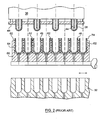
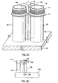
- Fig. 2 illustrates one embodiment of a robot take-off plate 60 that may be used in the cooling method of the present invention.
- the take-off plate 60 includes a plurality of hollow holders or take-off tubes 62.
- Hollow tubes 64 within holders 62 may carry cooling water for cooling the preforms 48 holders 62 may carry cooling water for cooling the preforms 48 when held in the take-off holders 62.
- Typical take-off plates which may be used for the take-off plate 60 are shown in US Patent No. 5,447,426 to Gessner et al. and in US Reissue Patent No. RE 33,237 to Delfer, III. In operation, the mouths of a plurality of holders 62 are aligned with the mold cores 38 of the mold plate 36.
- the take-off plate 60 can be provided with a number of holders 62 equal to the number of mold cores 38 or a larger number of holders 62 such as a multiple of the number of mold cores 38, for example, three or four times the number of mold cores 38.
- a number of holders 62 equal to the number of mold cores 38 or a larger number of holders 62 such as a multiple of the number of mold cores 38, for example, three or four times the number of mold cores 38.
- the method can be carried out irrespective of the relative number of molded preforms 48 retained by the holders 62. Nevertheless, in the preferred embodiment of the invention, the robot take-off plate 60 has a number of holders 62, which represent three times the number of cores 38. This means that the take-off plate 60 does not always carry a number of preforms or molded articles 48 equal to the number of holders 62. This also means that a single batch of preforms 48 can be moved back more than once into the mold area between the mold plates 32 and 36 to pick up further batches of preforms 48.
- the preforms 48 While being moved back and forth, the preforms 48 are continually cooled by intimate contact between the hollow tubes 64 within the take-off plate 60 and the external wall of the preforms 48, as shown in more detail in the aforementioned US Patent No. 5,447,426.
- the tubes 64 carry a cooling liquid such as water.
- the heat transfer between the tubes 64 and the hot preforms 48 released from the mold core 38 is performed through conduction. More particularly, any solid material incorporating any cooling means can be used and brought into intimate contact with the exterior wall of the preform 48 to cool the molded articles.
- a cooling system based on heat transfer between the molded article or preform 48 and the cooling tubes 64, the shape of the article or preform 48 can usually be maintained without deformations or scratches caused by handling.
- the neck finish portion 74 of the preforms 48 is not held in intimate contact with the cooling tubes 64 and, therefore, is not directly cooled by the tubes 64.
- This lack of cooling around the neck finish portion 74 may be a problem.
- those preforms having a thick wall neck finish portion 74 relative to the wall thickness of the remainder of the preform are a concern.
- this type of preform there may be sufficient heat stored in the neck finish portion 74 to reheat the portion 74 to its softening temperature. If this event occurs, the portion 74 will tend to deform.
- the present invention mitigates this problem by positively cooling the portion 74 immediately after the preform leaves the molding surface.
- U. S. Patent 6,171,541 further provides a cooling plate having a plurality of cooling tubes.
- a cooling tube extends into the interior of each preform during the time it is held in the holders 62 and the take-off plate 60 is not situated between the mold plates 32 and 36. While this additional cooling mechanism has been very effective in reducing the cycle time required to produce a preform it has been found to have some deficiencies.
- the cooling tubes provide cooling fluid directly onto the interior surface of a tip portion of the preform and provide a cooling path where the cooling fluid flows from the interior tip portion down the interior of the preform towards the neck finish portion where it escapes.
- the cooling fluid passing over the neck finish portion of the preform has been heated substantially by the preform before reaching the threaded neck finish portion. Consequently, the cooling tubes provide little cooling to the neck finish portion of the preform. While, with many preforms this is not a concern, since the hottest part of the preform is at the tip, it does become a concern when the walls of the neck portion are thick relative to the walls of the rest of the preform. Preforms having such thick walls in the neck or neck finish portion, retain a significant amount of heat in that portion that is not readily dissipated with the prior art design. Accordingly, it is necessary to provide a mechanism to quickly cool the neck portion of the preform in a controlled manner so that the thread on the preform will retain its dimensional integrity during the post-mold cooling process.
- the present invention solves the problem by providing a direct flow of coolant over the exterior surfaces of the neck or neck finish portion of the preform.
- the invention works so well that the preform may be cooled quickly and efficiently without the need for the internal cooling provided by the cooling tubes described in U.S. Patent 6,171,541 and, at the same time, improve the productivity of the injection-molding machine.
- it is desirable to include both cooling processes there may be some situations where it is desirable to include both cooling processes.
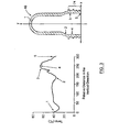
- FIG. 3 An example of a typical temperature profile of a preform 48 having a relatively thick neck finish portion 74 when removed from the mold cavity is shown in Figure 3. As shown therein the gate 1 and region 2 are cool relative to the local thin section 3 and local thick section 4 in the neck finish portion 74. This illustrates that most of the heat held in the preform 48, immediately upon transfer out of the mold, is held in the relatively thick neck finish portion 74 of the preform 48. The rapid and uniform cooling of this thread neck portion 74 will permit the removal of the preform from the take-off plate at the earliest point of the cycle.
- the heat in the preform is not distributed evenly across the width of the wall of the preform and, in fact, the central portion of the wall may be significantly hotter than the surface portions of the preform, the heat from the central portion of the walls dissipates through the external surfaces of the preform. In some cases, this can cause the outer surfaces of the walls of the preform to reheat to a point where they lose their rigidity. If this happens, the integrity of the preform surface will be lost.
- cooling means must be provided to prevent the internal heat in the walls of the thread neck finish portion 74 from heating the external wall surfaces to a softening temperature.
- the present invention provides direct cooling of the thread neck finish portion 74 so that the internal heat is dissipated without overheating the outer surfaces of the preform.
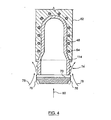
- FIG. 4 The basic concept of the invention is schematically illustrated in Figure 4.
- a preform 48 is held in a take-off holder 62 that is mounted in a take-off plate (not shown).
- the take-off holder 62 may include hollow cooling tubes 64.
- the invention provides a deflecting plate or insert 70 for deflecting pressurized air away from the internal surfaces of preform 48 and towards the external neck finish portion 74 of the preform 48. While not shown in Figure 4, some form of confining wall around the exterior of the neck finish portion 74 of the preform 48 may be provided. The manner in which the air can be channeled efficiently will be discussed hereinafter.
- the pressurized air flow 76 will draw a quantity of ambient air 78 along with it to thereby enhance the cooling effect.
- the neck finish portion 74 of the preform 48 is entirely cooled from the exterior inwardly.
- the intimate contact between the preform 48 and the take-off holder 62 provides cooling to the top body of the preform 48 through the cooling tubes 64.
- the pressurized air flow 76 provides cooling to the exterior of the neck finish portion 74 of the preform 48.
- the neck finish portion 74 must be stable before the preform 48 can be removed from the take-off plate 60.
- Fig. 10 An embodiment of the invention that uses both forms of cooling is shown in Fig. 10 and will be described hereinafter.
- the challenge is to combine all these forms of cooling to ensure that the preform is cooled in the shortest possible cycle time so that the preform can be removed from the take-off plate 60 in the shortest time without creating any deformities in the finished preform.
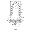
- FIG. 5 illustrates a further embodiment of the invention that cools the preform efficiently.
- a source of pressurized air 80 is directed into an air channel 82 in a base plate 84.
- An insert 86 is mounted on the base plate 84 by any suitable means.
- bolts 88 (only one shown) align and hold the insert 86 to the base plate 84.
- the circumferential surface 92 of the insert 86 is machined to create an air manifold in the space 90 between the insert 86 and the base plate 84.
- the air manifold ensures uniform distribution of the pressurized air 80 through the gap 96 in the path shown by arrows 98 to blow over the neck finish portion 74 of the preform 48.
- the air in the path shown by arrows 98 entrains ambient air along the path indicated by arrows 99 to thereby increase the cooling efficiency over the neck finish portion 74. This can mean a substantial reduction in the amount of pressurized air needed to cool the preform 48 thereby increasing the efficient use of cooling air.
- the cooling tubes 64 provide cooling to the dome 110 and body 112 of the preform 48.
- the support ledge 114 experiences cooling both from the cooling air shown by the arrows 98 and 99 and the cooling tubes 64 through contact with the holder 62.
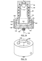
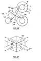
- FIG. 6A and 6B A further embodiment of the invention is shown schematically in Figures 6A and 6B.
- an insert 120 is provided.
- the insert 120 is channeled to provide cooling pressurized air 80 to the neck finish portion 74 of the preform 48 in a swirling vortex that cools the thread portion 74 of the preform 48.
- a base plate 84 is attached to a cooling plate (not shown) through a thread mount 140 or the like.
- the insert 120 is attached to the base plate 84 by bolts 88 (only one shown) but any suitable means of attachment could be used.
- a chamber 122 is created between the base plate 84 and the insert 120.
- the chamber 122 distributes cooling air through angled openings 124 in the insert 120.
- the openings 124 are directed towards the outer surface of the preform 48 at an angle to the major axis of the preform 48.
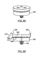
- FIGS 7A and 7B show a further embodiment of the invention.
- Cooling tubes 64 are provided within the take-off holder 62.
- the invention may be used with or without the cooling tubes in the take-off plate depending upon the cooling performance desired and the actual characteristics of the preform to be cooled.
- a sleeve 130 is attached to a base plate 132. As shown in Figure 7A, the sleeve 130 is threadedly attached to the base plate 132 by threads 136, but any suitable mounting means could be used.
- the base plate 132 is attached to a cooling plate that provides a source of cooling medium such as air to the base plate 132.
- the threaded mount 140 would attach the base plate 132 to a cooling plate.
- a plurality of preforms 48 are simultaneously cooled and each preform being so cooled requires its own cooling base plate 132 attached to the cooling plate.
- the number of cooling stations on the cooling plate would be determined by the number of take-off positions provided on the take-off plate.
- a chamber 144 is created between the sleeve 130 and the base plate 132 to receive pressurized air from a supply line 146.
- the pressurized air enters the chamber 144 through a line 148.
- Openings 150 in the sleeve 130 release the pressurized air onto the surface of the threaded neck finish portion 74 of the preform 48.
- the warming air rapidly escapes from the cooling area through discharge openings 152 in the base plate 132 and around the opening between the ledge 114 and the sleeve 130.
- the openings 150 may be disposed to direct the cooling air stream straight onto the threaded neck finish portion 74 or they may be angled to create a circular motion of the air stream around the threaded neck finish portion 74. In either case, the sleeve 130 should be designed to provide an even stream of cooling air over the entire threaded neck finish portion 74 so that the entire threaded neck finish portion 74 is cooled.
- FIGS 8A and 8B illustrate a further embodiment of the invention.
- the base plate 160 would be attached to a cooling plate by the threaded mount 140. Pressurized coolant flows through the threaded mount 140 to a channel in the insert 162.
- a gap 164 between the insert 162 and the base plate 160 is sized so as to control the distribution of pressurized air.
- the gap 164 is shaped to create streams of coolant out through the space 170 between the plate 160 and the insert 162.
- the circumferential area 166 on the insert 162 is chamfered to cause the air expelled through the space 170 between the plate 160 and the insert 162 to travel in a path shown by the arrows 168. This draws a large amount of ambient air 172 along with it so as to quickly cool a preform that would be located directly above the insert 162.
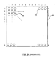
- Fig. 9A is a schematic plan view of a well-known take-off plate 60 such as is described in US Reissue Patent 33,237.
- the take-off plate 60 has three groups of take-off tubes or holders 62 for receiving three groups of preforms. As more fully described in the earlier US Reissue Patent 33,237, each group of holders 62 receives a set of preforms in one of three cycles of the take-off plate movement into an open mold and discharges its set of preforms to a conveyor or the like once every three cycles.
- the preforms can be held on the take-off plate 60 for three molding cycles and can be fully cooled before discharge to a conveyor.
- This sequence of operations is not a part of the present invention and will not be more fully described herein. In fact, other holding devices could be used in the implementation of the present invention as will become evident from the following description.
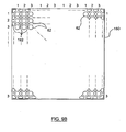
- Fig. 9B is a schematic plan view of the modified take-off plate incorporating the present invention.
- the take-off plate 180 includes the three sets of take-off tubes 62 for receiving and holding the preforms as before.
- the additional feature is the addition of coolant dispersion devices 182 which surround each take-off holder 62 and disperse a coolant such as cool air around the neck or neck finish portion of a preform held in the holder 62.
- Fig. 9C illustrates schematically one form of dispersion device.
- the holders 62 hold preforms 48.
- Supporting ledges 114 on preforms 48 rest on the top of the holders 62.
- Dispersion device 182 extends upwardly from the base of the take-off plate 180 and includes coolant outlet openings 184 which discharge coolant around the periphery of the neck finish portion 74 of the preform 48.
- Fig. 9D schematically illustrates the position of the dispersion device with only a single take-off holder 62 shown.
- the dispersion device 182 is mounted on the take-off plate 180.
- Channel 186 in take-off plate 180 provides coolant to the dispersion device 182.
- a positioner section 188 positions the dispersion device 182 to ensure that the openings 184 are properly positioned relative to the neck finish portion 74.
- FIGS 9E and 9F illustrate two further embodiments of air dispersion devices.
- a plurality of dispersion tubes 190 receive cooling air through a central passageway and distribute it over the neck finish portion 74 of the preforms 48 through arcuate nozzles 192 as shown by arrows 194.
- the arcuate nozzles 192 create an air flow around the neck finish portions 74 of the preforms 48.
- the preforms may be held within take-off holders 62 by vacuum in a manner well-known in the art. Support ledges 114 of preforms 48 rest on the top surface of the take-off holders 62.
- the dispersion tubes 190 may be maintained in a remote position when the holders 62 are being loaded with preforms 48 and subsequently rotated into operative position adjacent a preform 48 only after a preform 48 is transferred from the mold cavity to the associated take-off holder 62. This operation will ensure that the dispersion tubes 190 do not interfere with the transfer of the preforms into and out of the holders 62.
- the rest position of the dispersion tubes 190 is shown in outline at 196 in Fig. 9E and arrow 198 indicates the rotational movement of dispersion tubes 190 between its operative and rest positions. Alternatively, the dispersion tubes 190 could be raised and lowered to move them into and out of their operative and rest positions.
- an alternative air dispersion device 200 has tubes 202 that direct the cooling air onto the neck finish portion 74 of the preforms 48.
- the tubes 202 are shown directing air toward the neck finish portion 74 at a right angle to that surface.
- the tubes 202 could be angled so as to provide any desired direction of fluid flow over the neck finish portion 74 of a preform 48.
- Fig. 10 shows a further embodiment of the invention which combines the cooling effects of cooling tubes directing cooling fluid directly onto the interior tip of a preform and onto the exterior surface of the neck finish portion of the preform.
- elements similar to those shown in Fig. 5 are designated by the same reference characters. 5 are designated by the same reference characters.
- preform 14 is held in holder 62 with ledge 114 resting on the top surface of holder 62.
- Holder 62 may include cooling tubes 64. It should be understood that one may select any or all means of cooling the preform so as to best cool the preform efficiently without damage.
- pressurized air 80 is provided to air channel 82 where it is permitted to flow into space 90 and through gap 96 between insert 86 and base 84.
- Base 84 is attached to a cooling plate 206 through a threaded mount 208.
- the pressurized air 80 flows in the direction of arrows 98 to thereby cool the neck finish portion 74 of preform 14 in the same manner as described with reference to the embodiment shown in Fig. 5.
- pressurized air 80 also travels through channel 212 in cooling tube 214 to where it is discharged against the interior surface of the dome 110 of the preform 14 and flows past the interior surface of the preform 14 and is discharged through openings 218 in insert 86 and base 84 as indicated by the path illustrated by arrows 220.
- the interior surface of preform 14 is cooled by the flow of air through tube 212 simultaneously with the cooling of the exterior surface of the neck finish portion 74.
Landscapes
- Engineering & Computer Science (AREA)
- Manufacturing & Machinery (AREA)
- Mechanical Engineering (AREA)
- Moulds For Moulding Plastics Or The Like (AREA)
- Blow-Moulding Or Thermoforming Of Plastics Or The Like (AREA)
- Photovoltaic Devices (AREA)
- Processing And Handling Of Plastics And Other Materials For Molding In General (AREA)
- Heating, Cooling, Or Curing Plastics Or The Like In General (AREA)
- Injection Moulding Of Plastics Or The Like (AREA)
Claims (19)
- Kühlvorrichtung zum Nachformungskühlen eines geformten Gegenstandes (48) mit einer Öffnung und einer an diese unmittelbar angrenzenden äußeren Fläche (74) sowie einem Inneren, wobei die Kühlvorrichtung gekennzeichnet ist durch:einen Ablenker (84, 86, 130, 182), der an einem Rahmen (206) angeordnet ist, wobei der Ablenker im Betrieb unmittelbar benachbart, aber außerhalb der Öffnung des geformten zu kühlenden Gegenstandes (48) positionierbar ist, wobei der Ablenker eine Wand eines Führungskanals (90, 96, 124) aufweist, über welchen im Betrieb Kühlmittel (76, 98, 99) strömen kann, wobei der Ablenker und der Führungskanal so ausgebildet sind, daß sie das Kühlmittel direkt auf die Außenfläche (74) des geformten Gegenstandes (48) und von dem Inneren des geformten Gegenstandes weg abgeben, wodurch das Kühlen der Außenfläche des geformten Gegenstandes zumindest in unmittelbar Umgebung der Öffnung akzentuiert wird.
- Kühlvorrichtung nach Anspruch 1, die ferner aufweist:eine Eintrittsöffnung (82) für den Empfang eines Kühlmittelvorrates; undeine Kammer, um im Betrieb das Kühlmittelfluid von der Eintrittsöffnung zu einer Austrittsöffnung zu leiten, um das Kühlmittelfluid abzugeben.
- Kühlvorrichtung nach Anspruch 2, die ferner eine Basis (84) aufweist, die so ausgebildet ist, daß sie einen Einsatz (86) aufnimmt, wobei die Eintrittsöffnung (82) in der Basis (84) angeordnet ist, wobei die Kammer in einem Raum (90) zwischen der Basis (84) und dem Einsatz (86) gebildet ist, und die Austrittsöffnung in zumindest einem der beiden Teile i) der Basis oder ii) dem Einsatz angeordnet ist.
- Kühlvorrichtung nach Anspruch 1, die ferner ein Kühlrohr (214) aufweist, das an dem Einsatz (86) montiert ist, wobei das Kühlrohr (214) sich im Betrieb in das Innere des geformten Gegenstandes (48) erstreckt, wenn die exponierte Oberfläche des Halsfinishteiles (74) dem Kühlmittel (76, 98, 99) ausgesetzt wird, wobei das Kühlrohr (214) einen offenen Kanal aufweist, der mit der Kammer kommuniziert, um das Kühlmittel auf die Innenfläche aufzubringen.
- Kühlvorrichtung nach Anspruch 2 oder 3, die ferner so ausgebildet ist, daß sie den exponierten Teil einschließt.
- Kühlvorrichtung nach Anspruch 5, bei welcher eine Vielzahl von Austrittsöffnungen vorgesehen ist, die einwärts gerichtet angeordnet sind, um das Kühlmittelfluid auf die exponierte Oberfläche abzugeben.
- Kühlvorrichtung nach Anspruch 6, bei welcher die Austrittsöffnungen in einer Vielzahl von Säulen (190) vorgesehen sind, die um einen Umfang der exponierten Oberfläche angeordnet sind.
- Kühlvorrichtung nach Anspruch 6, bei welcher die Austrittsöffnungen so angeordnet sind, daß sie das Kühlmittel auf die Außenfläche unter einem spitzen Winkel zu dieser Oberfläche abgeben.
- Kühlvorrichtung nach Anspruch 6, die ferner Abgabekanäle in einem Basisteil aufweist.
- Kühlvorrichtung nach Anspruch 9, bei welcher die Basis (84) eine schalenförmige Struktur hat und der Einsatz (86) innerhalb der Basis (84) befestigt ist, und bei welcher ein Umfangsdüsenspalt (96) zwischen dem Einsatz (86) und der Basis (84) vorgesehen ist, wobei der Spalt (96) durch eine verjüngte Oberfläche an dem Einsatz und der Basis definiert ist, damit das durch den Spalt abgegebene Kühlmittel (98) Umgebungskühlmittel (99) über die Außenfläche des in dem Halter (62) gehaltenen geformten Gegenstandes (84) in einen Kühlpfad zieht.
- Kühlvorrichtung nach Anspruch 10, bei welcher der Düsenspalt (96) ein Venturi-Düsenspalt ist.
- Kühlvorrichtung nach einem der vorhergehenden Ansprüche, bei welcher die exponierte Außenfläche ein Halsfinishteil (74) eines Vorformlings ist.
- Austragplatte (180) einer Formungsmaschine für einen geformten Gegenstand, wobei die Austragplatte umfaßt:eine Vielzahl von Haltern (62), die an einer Platte (180) montiert sind, wobei jeder Halter (62) im Betrieb zum Halten eines geformten Gegenstandes (48) vorgesehen ist, wobei ein Teil (74) des geformten Gegenstandes (48) exponiert bleibt; gekennzeichnet durch:eine Kühlmittel-Verteilvorrichtung (182), die nahe jedem Halter (62) für einen geformten Gegenstand angeordnet ist;einen Kanal (186) in der Platte (180), wobei der Kanal (186) eine Kanalöffnung in jeder Verteilvorrichtung (182) umfaßt, wobei der Kanal im Betrieb jeder der Verteilvorrichtungen (182) Kühlmittel zuleitet; undAustrittsöffnungen (184) an jeder Verteilvorrichtung (182), die im Betrieb neben einem Halsteil des geformten Gegenstandes angeordnet sind, wobei die Austrittsöffnungen (184) oberhalb und dem Halter (62) benachbart angeordnet sind, um im Betrieb Kühlmittel dem exponierten Teil (74) der geformten Gegenstände (48) zuzuführen, die in den Haltern (62) gehalten sind.
- Austragplatte nach Anspruch 13, bei welcher das Kühlmittel als Druckkühlmittel zugeführt wird.
- Austragplatte nach Anspruch 13, bei welcher die Verteilvorrichtungen (182) mit der Platte durch Positionierer (188) verbunden sind.
- Kühlvorrichtung nach Anspruch 3, bei welcher der Ablenker eine Basis aufweist, die einen von folgenden Teilen hat:einen Randteil und einen Einsatz (86), der in den Randteil eingepaßt ist, um eine kreisförmige Düse zur Abgabe des Druckkühlmittels auf den Außenflächenteil zu bilden; undeinen Randteil und einen Einsatz (86), der innerhalb des Randteiles eingeschlossen ist, wobei der Einsatz Öffnungen (124, 150) zur Abgabe des Kühlmittels im Betrieb auf den Außenflächenteil (74) in einer vorbestimmten Richtung aufweist.
- Kühlvorrichtung nach Anspruch 16, bei welcher die vorbestimmte Richtung unter einem Winkel zum Außenflächenteil verläuft, damit das Kühlmittel in einer Wirbelströmung um den Außenflächenteil strömt.
- Kühlvorrichtung nach Anspruch 1, bei welcher Öffnungen (150) in einem Einsatz Druckkühlmittel in einer Richtung im wesentlichen senkrecht zur Außenfläche leiten.
- Kühlvorrichtung nach Anspruch 1, bei welcher der geformte Gegenstand im Betrieb in einem Halter (62) gehalten ist, der eine Rippe (114) zum Abstützen des geformten Gegenstandes (48) aufweist, wobei die Rippe (114) dem Gegenstand (74) gestattet, sich der Strömung des Druckkühlmittels auszusetzen.
Applications Claiming Priority (3)
| Application Number | Priority Date | Filing Date | Title |
|---|---|---|---|
| US09/948,917 US6802705B2 (en) | 2001-09-10 | 2001-09-10 | Post mold cooling assembly for molded article neck finishes |
| US948917 | 2001-09-10 | ||
| PCT/CA2002/000921 WO2003022548A1 (en) | 2001-09-10 | 2002-06-19 | Post mold cooling method and assembly for molded article neck finishes |
Publications (2)
| Publication Number | Publication Date |
|---|---|
| EP1436134A1 EP1436134A1 (de) | 2004-07-14 |
| EP1436134B1 true EP1436134B1 (de) | 2005-12-28 |
Family
ID=25488383
Family Applications (1)
| Application Number | Title | Priority Date | Filing Date |
|---|---|---|---|
| EP02742586A Expired - Lifetime EP1436134B1 (de) | 2001-09-10 | 2002-06-19 | Vorrichtung zum kühlen von halsenden von geformten gegenständen nach dem formen |
Country Status (9)
| Country | Link |
|---|---|
| US (1) | US6802705B2 (de) |
| EP (1) | EP1436134B1 (de) |
| JP (1) | JP4317449B2 (de) |
| CN (1) | CN1553850B (de) |
| AT (1) | ATE314187T1 (de) |
| CA (1) | CA2457084C (de) |
| DE (1) | DE60208410T2 (de) |
| MX (1) | MXPA04001998A (de) |
| WO (1) | WO2003022548A1 (de) |
Families Citing this family (26)
| Publication number | Priority date | Publication date | Assignee | Title |
|---|---|---|---|---|
| US6171541B1 (en) * | 1998-03-31 | 2001-01-09 | Husky Injection Molding Systems Ltd. | Preform post-mold cooling method and apparatus |
| ITRM20010138A1 (it) * | 2001-03-16 | 2002-09-16 | Sipa Spa | Dispositivo e metodo per il raffreddamento e il condizionamento termico di un oggetto tubolare. |
| US7264464B2 (en) * | 2003-06-09 | 2007-09-04 | Husky Injection Molding Systems Ltd. | Cooling tube with a low friction coating |
| US7232306B2 (en) * | 2003-08-22 | 2007-06-19 | Graham Packaging Company, Lp | Modified injection takeout tube |
| JP4646526B2 (ja) * | 2004-02-18 | 2011-03-09 | 株式会社日立製作所 | 記憶制御システム及び同システムの制御方法 |
| NL1026732C2 (nl) * | 2004-07-27 | 2006-01-30 | Tool Tech Holding B V | Koelinrichting voor preforms van kunststof houders, alsmede robotinrichting voorzien van een dergelijke koelinrichting en productie-inrichting voor preforms voorzien van een dergelijke robotinrichting. |
| US7550105B2 (en) * | 2005-02-23 | 2009-06-23 | Access Business Group International Llc | Apparatus and method for strengthening blow molded articles |
| JP2007144631A (ja) * | 2005-11-24 | 2007-06-14 | Dainippon Printing Co Ltd | プリフォームの取り出し治具 |
| DE102006028725A1 (de) * | 2005-11-30 | 2007-10-18 | Mht Mold & Hotrunner Technology Ag | Verfahren und System zur Nachbehandlung von Vorformlingen |
| US20070264383A1 (en) * | 2006-05-12 | 2007-11-15 | Husky Injection Molding Systems Ltd. | Mold-cooling device having vortex-inducing cooling-fluid chamber |
| US7421310B2 (en) * | 2006-06-12 | 2008-09-02 | Husky Injection Molding Systems Ltd. | Method and apparatus for controlling cooling rates during post-mold cooling of a molded article |
| US20090200698A1 (en) | 2006-06-12 | 2009-08-13 | Husky Injection Molding Systems Ltd. | Method and apparatus for post-mold cooling a molded article |
| US7485252B2 (en) | 2006-09-06 | 2009-02-03 | Graham Packaging Company, Lp | Method and apparatus for crystallizing the neck finish of a molded plastic article |
| US7595018B2 (en) * | 2006-10-16 | 2009-09-29 | Husky Injection Molding Systems Ltd. | Molded article picker |
| US7905721B2 (en) * | 2007-06-05 | 2011-03-15 | Husky Injection Molding Systems Ltd. | Air source device and a method for use in a molding system |
| US7780884B2 (en) * | 2007-08-20 | 2010-08-24 | Husky Injection Molding Systems Ltd. | Method for post-mold treatment of a molded article and an apparatus for implementing the method |
| EP2065158B1 (de) * | 2007-11-27 | 2018-05-30 | Plastipak BAWT S.à.r.l. | Kühlnagel zur Kühlung eines hohlen Formkörpers aus Kunststoff mittels eines Venturi-verstärkten Kühlungsflüssigkeitsstroms |
| CA2713824C (en) * | 2009-10-14 | 2016-01-26 | Pascal Zaffino | Mould with conformal cooling |
| US20190118442A9 (en) * | 2010-04-20 | 2019-04-25 | Honda Motor Co., Ltd. | Conforming cooling method and mold |
| JP5888731B2 (ja) * | 2012-01-31 | 2016-03-22 | 日精エー・エス・ビー機械株式会社 | 金型装置及び射出成形装置並びに射出成形方法 |
| DE102014205442A1 (de) | 2013-03-22 | 2014-09-25 | Otto Männer Innovation GmbH | Verfahren und Vorrichtung zum Temperieren des Halsabschlussbereichs gegossener Vorformlinge |
| CN103551508A (zh) * | 2013-11-14 | 2014-02-05 | 邵宏 | 带散热功能的节能型下金属模 |
| CN106457655B (zh) * | 2014-05-29 | 2019-07-09 | 帝斯克玛股份有限公司 | 向终止部提供冷却及反向压力的注射喷嘴 |
| EP3148779B1 (de) | 2014-05-29 | 2018-07-04 | Discma AG | Verfahren zur kühlung einer mündung und bereitstellung von gegendruck während der formung eines behälters |
| US10011052B2 (en) | 2015-01-13 | 2018-07-03 | YUDO ValuePro Lab Canada Inc. | Post-mold cooling method and apparatus with cyclone cooling effect |
| CN110181779A (zh) * | 2019-06-28 | 2019-08-30 | 广东星联精密机械有限公司 | 一种瓶坯模外冷却装置 |
Family Cites Families (27)
| Publication number | Priority date | Publication date | Assignee | Title |
|---|---|---|---|---|
| US4285657A (en) * | 1979-12-03 | 1981-08-25 | Ryder Leonard B | Injection blow molding apparatus |
| US4449913A (en) * | 1981-02-23 | 1984-05-22 | The Continental Group, Inc. | Rotary injection turret for the making of preforms |
| US4729732A (en) * | 1985-05-14 | 1988-03-08 | Husky Injection Molding Systems Ltd. | Carrying means for holding and cooling a parison |
| USRE33237E (en) * | 1987-03-23 | 1990-06-19 | Husky Injection Molding Systems Ltd. | Apparatus for producing hollow plastic articles |
| US4950152A (en) * | 1988-12-05 | 1990-08-21 | Electra Form, Inc. | Apparatus for producing preforms and blow molded articles |
| JPH0790595B2 (ja) | 1990-10-15 | 1995-10-04 | 日精エー・エス・ビー機械株式会社 | プリフォームの冷却装置 |
| US5232715A (en) * | 1990-10-15 | 1993-08-03 | Nissei Asb Machine Co., Ltd. | Apparatus for cooling a preform in a cooling tube |
| US5114327A (en) * | 1991-01-25 | 1992-05-19 | Williamson James T | Rapid cooling apparatus for an injection molding machine |
| US5447426A (en) * | 1993-07-06 | 1995-09-05 | Husky Injection Molding Systems Ltd. | Take-off plate device |
| JPH07171888A (ja) | 1993-12-21 | 1995-07-11 | Koyo Jidoki Kk | プリフォーム強制冷却装置 |
| US5702734A (en) * | 1994-12-19 | 1997-12-30 | Electra Form, Inc. | Take-out and cooling apparatus |
| CA2160644C (en) * | 1995-10-16 | 2005-05-24 | Jobst Ulrich Gellert | Cooled thread split inserts for injection molding preforms |
| US5707662A (en) * | 1995-11-01 | 1998-01-13 | Electra Form, Inc. | Parison molding and cooling apparatus |
| US5728409A (en) * | 1996-03-06 | 1998-03-17 | Husky Injection Molding Systems Ltd. | Turret article molding machine |
| NL1005872C2 (nl) * | 1997-04-22 | 1998-10-29 | Inter Tooling Services Bv | Spuitgietmachine voor het spuitgieten van preforms voor kunststof flessen en soortgelijke houders. |
| US6171541B1 (en) | 1998-03-31 | 2001-01-09 | Husky Injection Molding Systems Ltd. | Preform post-mold cooling method and apparatus |
| US6461556B2 (en) * | 1998-03-31 | 2002-10-08 | Husky Injection Molding Systems, Ltd. | Post-mold cooling method and apparatus |
| DE29810567U1 (de) | 1998-06-12 | 1998-09-17 | Kronseder Maschf Krones | Vorrichtung zum Konditionieren von Vorformlingen aus thermoplastischem Kunststoff |
| JP3076033B1 (ja) * | 1998-09-14 | 2000-08-14 | 松下電器産業株式会社 | 光学情報の記録再生装置および情報記録媒体 |
| US6059557A (en) * | 1998-10-07 | 2000-05-09 | Husky Injection Molding Systems Ltd. | Cooling device attached to index machine |
| JP2000108170A (ja) | 1998-10-08 | 2000-04-18 | Mitsubishi Heavy Ind Ltd | 成形品取出装置 |
| CA2255798C (en) * | 1998-12-07 | 2008-06-17 | Jobst Ulrich Gellert | Injection molding cooling core having spiral grooves |
| EP1066947A3 (de) * | 1999-06-30 | 2002-12-18 | HEKUMA Herbst Maschinenbau GmbH | Temperierverfahren sowie Kunststoff-Spritzgiessmaschine mit einem Handlingsystem |
| JP2001018265A (ja) | 1999-06-30 | 2001-01-23 | Hekuma Herbst Maschinenbau Gmbh | 樹脂製品のハンドリング装置および方法 |
| US6223541B1 (en) * | 1999-08-17 | 2001-05-01 | Fasti, Farrag & Stipsits Gesmbh | Method and device for the after-cooling of a preform in the injection molding process |
| US6299804B1 (en) | 1999-09-16 | 2001-10-09 | Husky Injection Molding Systems Ltd. | Air cooling system for preform molding |
| CH695332A5 (de) | 2000-12-22 | 2006-04-13 | Netstal Ag Maschf Giesserei | Nachkühler für hülsenförmige Spritzgiessteile, sowie die Verwendung des Nachkühlers. |
-
2001
- 2001-09-10 US US09/948,917 patent/US6802705B2/en not_active Expired - Fee Related
-
2002
- 2002-06-19 MX MXPA04001998A patent/MXPA04001998A/es active IP Right Grant
- 2002-06-19 CN CN02817708.8A patent/CN1553850B/zh not_active Expired - Fee Related
- 2002-06-19 EP EP02742586A patent/EP1436134B1/de not_active Expired - Lifetime
- 2002-06-19 DE DE60208410T patent/DE60208410T2/de not_active Expired - Lifetime
- 2002-06-19 AT AT02742586T patent/ATE314187T1/de active
- 2002-06-19 CA CA002457084A patent/CA2457084C/en not_active Expired - Fee Related
- 2002-06-19 WO PCT/CA2002/000921 patent/WO2003022548A1/en active IP Right Grant
- 2002-06-19 JP JP2003526655A patent/JP4317449B2/ja not_active Expired - Fee Related
Also Published As
| Publication number | Publication date |
|---|---|
| JP4317449B2 (ja) | 2009-08-19 |
| CA2457084A1 (en) | 2003-03-20 |
| DE60208410D1 (de) | 2006-02-02 |
| WO2003022548A1 (en) | 2003-03-20 |
| CA2457084C (en) | 2007-10-30 |
| ATE314187T1 (de) | 2006-01-15 |
| CN1553850A (zh) | 2004-12-08 |
| JP2005501765A (ja) | 2005-01-20 |
| DE60208410T2 (de) | 2006-09-07 |
| US20030057598A1 (en) | 2003-03-27 |
| MXPA04001998A (es) | 2004-07-08 |
| CN1553850B (zh) | 2010-10-06 |
| US6802705B2 (en) | 2004-10-12 |
| EP1436134A1 (de) | 2004-07-14 |
Similar Documents
| Publication | Publication Date | Title |
|---|---|---|
| EP1436134B1 (de) | Vorrichtung zum kühlen von halsenden von geformten gegenständen nach dem formen | |
| US6488878B1 (en) | Preform post-mold cooling method and apparatus | |
| AU746598C (en) | Preform post-mold cooling method and apparatus | |
| US6461556B2 (en) | Post-mold cooling method and apparatus | |
| US6663813B2 (en) | Method for cooling molded articles | |
| US6770239B2 (en) | Method for localized preform cooling outside the mold | |
| US6139789A (en) | Compact post-mold cooling device and method for thermally conditioning molded articles | |
| EP1260339B1 (de) | Verfahren und Vorrichtung zum Kühlen eines Vorformlings nach der Formung, sowie Kühlkörper |
Legal Events
| Date | Code | Title | Description |
|---|---|---|---|
| PUAI | Public reference made under article 153(3) epc to a published international application that has entered the european phase |
Free format text: ORIGINAL CODE: 0009012 |
|
| 17P | Request for examination filed |
Effective date: 20040413 |
|
| AK | Designated contracting states |
Kind code of ref document: A1 Designated state(s): AT BE CH CY DE DK ES FI FR GB GR IE IT LI LU MC NL PT SE TR |
|
| AX | Request for extension of the european patent |
Extension state: AL LT LV MK RO SI |
|
| 17Q | First examination report despatched |
Effective date: 20040818 |
|
| GRAP | Despatch of communication of intention to grant a patent |
Free format text: ORIGINAL CODE: EPIDOSNIGR1 |
|
| RTI1 | Title (correction) |
Free format text: POST MOLD COOLING ASSEMBLY FOR MOLDED ARTICLE NECK FINISHES |
|
| GRAS | Grant fee paid |
Free format text: ORIGINAL CODE: EPIDOSNIGR3 |
|
| GRAA | (expected) grant |
Free format text: ORIGINAL CODE: 0009210 |
|
| AK | Designated contracting states |
Kind code of ref document: B1 Designated state(s): AT BE CH CY DE DK ES FI FR GB GR IE IT LI LU MC NL PT SE TR |
|
| PG25 | Lapsed in a contracting state [announced via postgrant information from national office to epo] |
Ref country code: BE Free format text: LAPSE BECAUSE OF FAILURE TO SUBMIT A TRANSLATION OF THE DESCRIPTION OR TO PAY THE FEE WITHIN THE PRESCRIBED TIME-LIMIT Effective date: 20051228 Ref country code: FI Free format text: LAPSE BECAUSE OF FAILURE TO SUBMIT A TRANSLATION OF THE DESCRIPTION OR TO PAY THE FEE WITHIN THE PRESCRIBED TIME-LIMIT Effective date: 20051228 |
|
| REG | Reference to a national code |
Ref country code: GB Ref legal event code: FG4D |
|
| REG | Reference to a national code |
Ref country code: CH Ref legal event code: EP |
|
| REG | Reference to a national code |
Ref country code: IE Ref legal event code: FG4D |
|
| REF | Corresponds to: |
Ref document number: 60208410 Country of ref document: DE Date of ref document: 20060202 Kind code of ref document: P |
|
| REG | Reference to a national code |
Ref country code: CH Ref legal event code: NV Representative=s name: BOVARD AG PATENTANWAELTE |
|
| PG25 | Lapsed in a contracting state [announced via postgrant information from national office to epo] |
Ref country code: GR Free format text: LAPSE BECAUSE OF FAILURE TO SUBMIT A TRANSLATION OF THE DESCRIPTION OR TO PAY THE FEE WITHIN THE PRESCRIBED TIME-LIMIT Effective date: 20060328 Ref country code: DK Free format text: LAPSE BECAUSE OF FAILURE TO SUBMIT A TRANSLATION OF THE DESCRIPTION OR TO PAY THE FEE WITHIN THE PRESCRIBED TIME-LIMIT Effective date: 20060328 Ref country code: SE Free format text: LAPSE BECAUSE OF FAILURE TO SUBMIT A TRANSLATION OF THE DESCRIPTION OR TO PAY THE FEE WITHIN THE PRESCRIBED TIME-LIMIT Effective date: 20060328 |
|
| PG25 | Lapsed in a contracting state [announced via postgrant information from national office to epo] |
Ref country code: ES Free format text: LAPSE BECAUSE OF FAILURE TO SUBMIT A TRANSLATION OF THE DESCRIPTION OR TO PAY THE FEE WITHIN THE PRESCRIBED TIME-LIMIT Effective date: 20060408 |
|
| PG25 | Lapsed in a contracting state [announced via postgrant information from national office to epo] |
Ref country code: PT Free format text: LAPSE BECAUSE OF FAILURE TO SUBMIT A TRANSLATION OF THE DESCRIPTION OR TO PAY THE FEE WITHIN THE PRESCRIBED TIME-LIMIT Effective date: 20060529 |
|
| PG25 | Lapsed in a contracting state [announced via postgrant information from national office to epo] |
Ref country code: IE Free format text: LAPSE BECAUSE OF NON-PAYMENT OF DUE FEES Effective date: 20060619 |
|
| PG25 | Lapsed in a contracting state [announced via postgrant information from national office to epo] |
Ref country code: MC Free format text: LAPSE BECAUSE OF NON-PAYMENT OF DUE FEES Effective date: 20060630 |
|
| ET | Fr: translation filed | ||
| PLBE | No opposition filed within time limit |
Free format text: ORIGINAL CODE: 0009261 |
|
| STAA | Information on the status of an ep patent application or granted ep patent |
Free format text: STATUS: NO OPPOSITION FILED WITHIN TIME LIMIT |
|
| 26N | No opposition filed |
Effective date: 20060929 |
|
| REG | Reference to a national code |
Ref country code: IE Ref legal event code: MM4A |
|
| PG25 | Lapsed in a contracting state [announced via postgrant information from national office to epo] |
Ref country code: TR Free format text: LAPSE BECAUSE OF FAILURE TO SUBMIT A TRANSLATION OF THE DESCRIPTION OR TO PAY THE FEE WITHIN THE PRESCRIBED TIME-LIMIT Effective date: 20051228 Ref country code: LU Free format text: LAPSE BECAUSE OF NON-PAYMENT OF DUE FEES Effective date: 20060619 |
|
| PG25 | Lapsed in a contracting state [announced via postgrant information from national office to epo] |
Ref country code: CY Free format text: LAPSE BECAUSE OF FAILURE TO SUBMIT A TRANSLATION OF THE DESCRIPTION OR TO PAY THE FEE WITHIN THE PRESCRIBED TIME-LIMIT Effective date: 20051228 |
|
| REG | Reference to a national code |
Ref country code: CH Ref legal event code: PFA Owner name: HUSKY INJECTION MOLDING SYSTEMS LTD. Free format text: HUSKY INJECTION MOLDING SYSTEMS LTD.#AMC/IP GROUP, 500 QUEEN STREET SOUTH#BOLTON, ONTARIO L7E 5S5 (CA) -TRANSFER TO- HUSKY INJECTION MOLDING SYSTEMS LTD.#AMC/IP GROUP, 500 QUEEN STREET SOUTH#BOLTON, ONTARIO L7E 5S5 (CA) |
|
| PGFP | Annual fee paid to national office [announced via postgrant information from national office to epo] |
Ref country code: FR Payment date: 20110504 Year of fee payment: 10 |
|
| PGFP | Annual fee paid to national office [announced via postgrant information from national office to epo] |
Ref country code: AT Payment date: 20120412 Year of fee payment: 11 |
|
| REG | Reference to a national code |
Ref country code: FR Ref legal event code: ST Effective date: 20130228 |
|
| PG25 | Lapsed in a contracting state [announced via postgrant information from national office to epo] |
Ref country code: FR Free format text: LAPSE BECAUSE OF NON-PAYMENT OF DUE FEES Effective date: 20120702 |
|
| REG | Reference to a national code |
Ref country code: DE Ref legal event code: R082 Ref document number: 60208410 Country of ref document: DE Representative=s name: PATRONUS IP PATENT- & RECHTSANWAELTE BERNHARD , DE Ref country code: DE Ref legal event code: R082 Ref document number: 60208410 Country of ref document: DE Representative=s name: CORINNA VOSSIUS IP GROUP PATENT- UND RECHTSANW, DE |
|
| PGFP | Annual fee paid to national office [announced via postgrant information from national office to epo] |
Ref country code: GB Payment date: 20130516 Year of fee payment: 12 Ref country code: CH Payment date: 20130510 Year of fee payment: 12 Ref country code: DE Payment date: 20130524 Year of fee payment: 12 |
|
| REG | Reference to a national code |
Ref country code: DE Ref legal event code: R082 Ref document number: 60208410 Country of ref document: DE Representative=s name: CORINNA VOSSIUS IP GROUP PATENT- UND RECHTSANW, DE |
|
| PGFP | Annual fee paid to national office [announced via postgrant information from national office to epo] |
Ref country code: NL Payment date: 20130328 Year of fee payment: 12 Ref country code: IT Payment date: 20130624 Year of fee payment: 12 |
|
| REG | Reference to a national code |
Ref country code: DE Ref legal event code: R119 Ref document number: 60208410 Country of ref document: DE |
|
| REG | Reference to a national code |
Ref country code: NL Ref legal event code: V1 Effective date: 20150101 |
|
| REG | Reference to a national code |
Ref country code: CH Ref legal event code: PL |
|
| REG | Reference to a national code |
Ref country code: AT Ref legal event code: MM01 Ref document number: 314187 Country of ref document: AT Kind code of ref document: T Effective date: 20140619 |
|
| GBPC | Gb: european patent ceased through non-payment of renewal fee |
Effective date: 20140619 |
|
| REG | Reference to a national code |
Ref country code: DE Ref legal event code: R119 Ref document number: 60208410 Country of ref document: DE Effective date: 20150101 |
|
| PG25 | Lapsed in a contracting state [announced via postgrant information from national office to epo] |
Ref country code: NL Free format text: LAPSE BECAUSE OF NON-PAYMENT OF DUE FEES Effective date: 20150101 |
|
| PG25 | Lapsed in a contracting state [announced via postgrant information from national office to epo] |
Ref country code: CH Free format text: LAPSE BECAUSE OF NON-PAYMENT OF DUE FEES Effective date: 20140630 Ref country code: DE Free format text: LAPSE BECAUSE OF NON-PAYMENT OF DUE FEES Effective date: 20150101 Ref country code: IT Free format text: LAPSE BECAUSE OF NON-PAYMENT OF DUE FEES Effective date: 20140619 Ref country code: LI Free format text: LAPSE BECAUSE OF NON-PAYMENT OF DUE FEES Effective date: 20140630 |
|
| PG25 | Lapsed in a contracting state [announced via postgrant information from national office to epo] |
Ref country code: GB Free format text: LAPSE BECAUSE OF NON-PAYMENT OF DUE FEES Effective date: 20140619 Ref country code: AT Free format text: LAPSE BECAUSE OF NON-PAYMENT OF DUE FEES Effective date: 20140619 |