EP1435261A1 - Hollow fiber film and method for production thereof - Google Patents
Hollow fiber film and method for production thereof Download PDFInfo
- Publication number
- EP1435261A1 EP1435261A1 EP02770214A EP02770214A EP1435261A1 EP 1435261 A1 EP1435261 A1 EP 1435261A1 EP 02770214 A EP02770214 A EP 02770214A EP 02770214 A EP02770214 A EP 02770214A EP 1435261 A1 EP1435261 A1 EP 1435261A1
- Authority
- EP
- European Patent Office
- Prior art keywords
- hollow fiber
- fiber membrane
- polyvinylidene fluoride
- temperature
- water
- Prior art date
- Legal status (The legal status is an assumption and is not a legal conclusion. Google has not performed a legal analysis and makes no representation as to the accuracy of the status listed.)
- Granted
Links
Images


Classifications
-
- B—PERFORMING OPERATIONS; TRANSPORTING
- B01—PHYSICAL OR CHEMICAL PROCESSES OR APPARATUS IN GENERAL
- B01D—SEPARATION
- B01D67/00—Processes specially adapted for manufacturing semi-permeable membranes for separation processes or apparatus
- B01D67/0081—After-treatment of organic or inorganic membranes
- B01D67/0088—Physical treatment with compounds, e.g. swelling, coating or impregnation
-
- C—CHEMISTRY; METALLURGY
- C08—ORGANIC MACROMOLECULAR COMPOUNDS; THEIR PREPARATION OR CHEMICAL WORKING-UP; COMPOSITIONS BASED THEREON
- C08J—WORKING-UP; GENERAL PROCESSES OF COMPOUNDING; AFTER-TREATMENT NOT COVERED BY SUBCLASSES C08B, C08C, C08F, C08G or C08H
- C08J5/00—Manufacture of articles or shaped materials containing macromolecular substances
- C08J5/20—Manufacture of shaped structures of ion-exchange resins
- C08J5/22—Films, membranes or diaphragms
-
- B—PERFORMING OPERATIONS; TRANSPORTING
- B01—PHYSICAL OR CHEMICAL PROCESSES OR APPARATUS IN GENERAL
- B01D—SEPARATION
- B01D61/00—Processes of separation using semi-permeable membranes, e.g. dialysis, osmosis or ultrafiltration; Apparatus, accessories or auxiliary operations specially adapted therefor
- B01D61/14—Ultrafiltration; Microfiltration
- B01D61/145—Ultrafiltration
-
- B—PERFORMING OPERATIONS; TRANSPORTING
- B01—PHYSICAL OR CHEMICAL PROCESSES OR APPARATUS IN GENERAL
- B01D—SEPARATION
- B01D61/00—Processes of separation using semi-permeable membranes, e.g. dialysis, osmosis or ultrafiltration; Apparatus, accessories or auxiliary operations specially adapted therefor
- B01D61/14—Ultrafiltration; Microfiltration
- B01D61/147—Microfiltration
-
- B—PERFORMING OPERATIONS; TRANSPORTING
- B01—PHYSICAL OR CHEMICAL PROCESSES OR APPARATUS IN GENERAL
- B01D—SEPARATION
- B01D65/00—Accessories or auxiliary operations, in general, for separation processes or apparatus using semi-permeable membranes
- B01D65/02—Membrane cleaning or sterilisation ; Membrane regeneration
-
- B—PERFORMING OPERATIONS; TRANSPORTING
- B01—PHYSICAL OR CHEMICAL PROCESSES OR APPARATUS IN GENERAL
- B01D—SEPARATION
- B01D67/00—Processes specially adapted for manufacturing semi-permeable membranes for separation processes or apparatus
- B01D67/0002—Organic membrane manufacture
- B01D67/0009—Organic membrane manufacture by phase separation, sol-gel transition, evaporation or solvent quenching
- B01D67/0016—Coagulation
- B01D67/00165—Composition of the coagulation baths
-
- B—PERFORMING OPERATIONS; TRANSPORTING
- B01—PHYSICAL OR CHEMICAL PROCESSES OR APPARATUS IN GENERAL
- B01D—SEPARATION
- B01D67/00—Processes specially adapted for manufacturing semi-permeable membranes for separation processes or apparatus
- B01D67/0002—Organic membrane manufacture
- B01D67/0009—Organic membrane manufacture by phase separation, sol-gel transition, evaporation or solvent quenching
- B01D67/0018—Thermally induced processes [TIPS]
-
- B—PERFORMING OPERATIONS; TRANSPORTING
- B01—PHYSICAL OR CHEMICAL PROCESSES OR APPARATUS IN GENERAL
- B01D—SEPARATION
- B01D67/00—Processes specially adapted for manufacturing semi-permeable membranes for separation processes or apparatus
- B01D67/0002—Organic membrane manufacture
- B01D67/0023—Organic membrane manufacture by inducing porosity into non porous precursor membranes
- B01D67/0025—Organic membrane manufacture by inducing porosity into non porous precursor membranes by mechanical treatment, e.g. pore-stretching
- B01D67/0027—Organic membrane manufacture by inducing porosity into non porous precursor membranes by mechanical treatment, e.g. pore-stretching by stretching
-
- B—PERFORMING OPERATIONS; TRANSPORTING
- B01—PHYSICAL OR CHEMICAL PROCESSES OR APPARATUS IN GENERAL
- B01D—SEPARATION
- B01D67/00—Processes specially adapted for manufacturing semi-permeable membranes for separation processes or apparatus
- B01D67/0081—After-treatment of organic or inorganic membranes
- B01D67/0093—Chemical modification
- B01D67/00931—Chemical modification by introduction of specific groups after membrane formation, e.g. by grafting
-
- B—PERFORMING OPERATIONS; TRANSPORTING
- B01—PHYSICAL OR CHEMICAL PROCESSES OR APPARATUS IN GENERAL
- B01D—SEPARATION
- B01D69/00—Semi-permeable membranes for separation processes or apparatus characterised by their form, structure or properties; Manufacturing processes specially adapted therefor
- B01D69/02—Semi-permeable membranes for separation processes or apparatus characterised by their form, structure or properties; Manufacturing processes specially adapted therefor characterised by their properties
-
- B—PERFORMING OPERATIONS; TRANSPORTING
- B01—PHYSICAL OR CHEMICAL PROCESSES OR APPARATUS IN GENERAL
- B01D—SEPARATION
- B01D69/00—Semi-permeable membranes for separation processes or apparatus characterised by their form, structure or properties; Manufacturing processes specially adapted therefor
- B01D69/08—Hollow fibre membranes
-
- B—PERFORMING OPERATIONS; TRANSPORTING
- B01—PHYSICAL OR CHEMICAL PROCESSES OR APPARATUS IN GENERAL
- B01D—SEPARATION
- B01D71/00—Semi-permeable membranes for separation processes or apparatus characterised by the material; Manufacturing processes specially adapted therefor
- B01D71/06—Organic material
- B01D71/30—Polyalkenyl halides
- B01D71/32—Polyalkenyl halides containing fluorine atoms
- B01D71/34—Polyvinylidene fluoride
-
- C—CHEMISTRY; METALLURGY
- C02—TREATMENT OF WATER, WASTE WATER, SEWAGE, OR SLUDGE
- C02F—TREATMENT OF WATER, WASTE WATER, SEWAGE, OR SLUDGE
- C02F1/00—Treatment of water, waste water, or sewage
- C02F1/44—Treatment of water, waste water, or sewage by dialysis, osmosis or reverse osmosis
- C02F1/444—Treatment of water, waste water, or sewage by dialysis, osmosis or reverse osmosis by ultrafiltration or microfiltration
-
- B—PERFORMING OPERATIONS; TRANSPORTING
- B01—PHYSICAL OR CHEMICAL PROCESSES OR APPARATUS IN GENERAL
- B01D—SEPARATION
- B01D2321/00—Details relating to membrane cleaning, regeneration, sterilization or to the prevention of fouling
- B01D2321/12—Use of permeate
-
- B—PERFORMING OPERATIONS; TRANSPORTING
- B01—PHYSICAL OR CHEMICAL PROCESSES OR APPARATUS IN GENERAL
- B01D—SEPARATION
- B01D2321/00—Details relating to membrane cleaning, regeneration, sterilization or to the prevention of fouling
- B01D2321/16—Use of chemical agents
- B01D2321/168—Use of other chemical agents
-
- B—PERFORMING OPERATIONS; TRANSPORTING
- B01—PHYSICAL OR CHEMICAL PROCESSES OR APPARATUS IN GENERAL
- B01D—SEPARATION
- B01D2321/00—Details relating to membrane cleaning, regeneration, sterilization or to the prevention of fouling
- B01D2321/18—Use of gases
- B01D2321/185—Aeration
-
- B—PERFORMING OPERATIONS; TRANSPORTING
- B01—PHYSICAL OR CHEMICAL PROCESSES OR APPARATUS IN GENERAL
- B01D—SEPARATION
- B01D2321/00—Details relating to membrane cleaning, regeneration, sterilization or to the prevention of fouling
- B01D2321/20—By influencing the flow
- B01D2321/2033—By influencing the flow dynamically
- B01D2321/2058—By influencing the flow dynamically by vibration of the membrane, e.g. with an actuator
-
- B—PERFORMING OPERATIONS; TRANSPORTING
- B01—PHYSICAL OR CHEMICAL PROCESSES OR APPARATUS IN GENERAL
- B01D—SEPARATION
- B01D2323/00—Details relating to membrane preparation
- B01D2323/08—Specific temperatures applied
- B01D2323/082—Cooling
-
- B—PERFORMING OPERATIONS; TRANSPORTING
- B01—PHYSICAL OR CHEMICAL PROCESSES OR APPARATUS IN GENERAL
- B01D—SEPARATION
- B01D2323/00—Details relating to membrane preparation
- B01D2323/12—Specific ratios of components used
-
- B—PERFORMING OPERATIONS; TRANSPORTING
- B01—PHYSICAL OR CHEMICAL PROCESSES OR APPARATUS IN GENERAL
- B01D—SEPARATION
- B01D2323/00—Details relating to membrane preparation
- B01D2323/219—Specific solvent system
- B01D2323/22—Specific non-solvents or non-solvent system
Definitions
- the present invention relates to hollow fiber membranes and methods of producing the same.
- the present invention relates to a method of producing a hollow fiber microfiltration membrane and hollow fiber ultrafiltration membrane to be used in water treatments, such as drainage treatments, water purification treatments, and industrial water production, and relates to a hollow fiber membrane produced by the method.
- Separation membranes such as microfiltration membranes and ultrafiltration membranes have been used in various fields such as the food industry, medical treatment, water production, and waste water treatment. In recent years, separation membranes have also been used in drinking water production, namely, water purification treatment. In the water treatment such as water purification, a large volume of water must be treated; hence, hollow fiber membranes having a large effective filtration area per unit volume are generally used. An improvement in the water permeability of the hollow fiber membrane allows a reduction in membrane area and a reduction in manufacturing expense due to the reduced size. Such an improvement is also advantageous since exchanging membranes becomes more cost effective and the membranes require a smaller installation area.
- Fungicides such as sodium hypochlorite are added for sterilizing permeated water and preventing biofouling of the membrane in some cases. Furthermore, the membranes are washed with acids such as hydrochloric acid, citric acid, and oxalic acid, alkalis such as sodium hydroxide, and surfactants, if necessary.
- acids such as hydrochloric acid, citric acid, and oxalic acid, alkalis such as sodium hydroxide, and surfactants, if necessary.
- polyvinylidene fluoride separation membranes having high chemical resistance have been used recently.
- contamination by chlorine-resistant pathogenic microorganisms such as cryptosporidium has become common in the last few years. Under such circumstances, hollow fiber membranes must have high tensile properties to prevent contamination by raw water caused by fracture of the membranes.
- raw water represents river water, lake water, ground water, seawater, waste water, discharged water, and treated water thereof.
- Polyvinylidene fluoride separation membranes are prepared by the following methods: (1) A polyvinylidene fluoride solution (polyvinylidene fluoride dissolved in a good solvent) is extruded from a spinneret or cast onto a glass plate held at a temperature that is considerably lower than the melting point of the polyvinylidene fluoride, and the shaped resin is brought into contact with a liquid containing a nonsolvent to form a porous structure by phase separation induced by the nonsolvent (wet process disclosed in Japanese Examined Patent Application Publication No.
- the wet process exhibits unevenness in phase separation in the thickness direction that causes the formation of a membrane having an asymmetric structure containing macrovoids; hence, the membrane has insufficient mechanical strength. Furthermore, there are many production parameters on which the structure and the properties of the membrane depend; the production steps are not controllable and reproducible.
- the melt extraction process yields a relatively uniform, high-strength membrane with no macrovoids; however, poor dispersion of the inorganic particles can cause defects such as pinholes. Furthermore, the melt extraction process has a disadvantage of extremely high production cost.
- An object of the present invention is to provide a hollow fiber membrane that is composed of a polyvinylidene fluoride resin having high chemical resistance and shows high mechanical strength and high water permeability.
- Another object of the present invention is to provide a method of producing the hollow fiber membrane with reduced environmental load at low cost.
- a method of producing a hollow fiber membrane includes discharging a polyvinylidene fluoride solution comprising a polyvinylidene fluoride resin and a poor solvent at a temperature above a phase separation temperature into a cooling bath at a temperature below the phase separation temperature to coagulate the polyvinylidene fluoride resin.
- a hollow fiber membrane comprises a polyvinylidene fluoride resin having spherical structures that have an average diameter in the range of 0.3 to 30 ⁇ m.
- a hollow fiber membrane module includes the above hollow fiber membrane.
- a water separator includes the hollow fiber membrane module.
- a method of producing permeated water from raw water uses the above water separator.
- the method comprises bringing the membrane into contact with chlorine in an amount corresponding to the organic content (natural organic matter content) in the raw water.
- Polyvinylidene fluoride resins in the present invention represent resins containing vinylidene fluoride homopolymer and/or vinylidene fluoride copolymer.
- the polyvinylidene fluoride resins may contain different types of vinylidene fluoride copolymer.
- the vinylidene fluoride copolymer has a vinylidene fluoride structural unit.
- Typical vinylidene fluoride copolymers are polymers of vinylidene fluoride monomer and fluorine-containing comonomers, such as vinyl fluoride, tetrafluoroethylene, hexafluoropropylene, and trifluorochloroethylene. These comonomers may be used alone or in combination.
- the vinylidene fluoride copolymer in the present invention may contain any other monomer such as ethylene as long as the copolymer exhibits the advantages in the present invention.
- Poor solvents in the present invention represent liquids that cannot dissolve 5 percent by weight or more of polyvinylidene fluoride resin at a low temperature of less than 60°C and can dissolve the resin at a high temperature in the range of 60°C to the melting point of the resin (for example, about 178°C for a vinylidene fluoride homopolymer resin).
- good solvents represent liquids that can dissolve 5 percent by weight or more of polyvinylidene fluoride resin at a low temperature of less than 60°C
- nonsolvents represent liquids that can neither dissolve nor swell the polyvinylidene fluoride resin at any temperature lower than the melting point of the polyvinylidene fluoride resin.
- Examples of poor solvents include medium-chain alkyl ketones, esters, glycol esters and organic carbonates, i.e., cyclohexanone, isophorone, ⁇ -butylactone, methyl isoamyl ketone, dimethyl phthalate, propylene glycol methyl ether, propylene carbonate, diacetone alcohol, and glycerol triacetate.
- cyclohexanone, isophorone, ⁇ -butylactone, and dimethyl phthalate are preferable.
- Cyclohexanone and ⁇ -butylactone are more preferable.
- Examples of good solvents include lower alkyl ketones, esters, and amides, i.e., N-methyl-2-pyrrolidone, dimethyl sulfoxide, dimethyl acetamide, dimethyl formamide, methyl ethyl ketone, acetone, tetrahydrofuran, tetramethylurea, and trimethyl phosphate.
- amides i.e., N-methyl-2-pyrrolidone, dimethyl sulfoxide, dimethyl acetamide, dimethyl formamide, methyl ethyl ketone, acetone, tetrahydrofuran, tetramethylurea, and trimethyl phosphate.
- nonsolvents include water; aliphatic, aromatic, and chlorinated hydrocarbons, i.e., hexane, pentane, benzene, toluene, methanol, carbon tetrachloride, and o-dichlorobenzene, trichloroethylene; hydroxyl-containing liquids, i.e., ethanol and low-molecular weight polyethylene glycol; and other chlorinated organic liquids.
- the polyvinylidene fluoride resin is dissolved into a poor solvent at a temperature that is higher than a phase separation temperature, namely, 80°C to 175°C, and preferably 100°C to 170°C, to prepare a polyvinylidene fluoride resin solution.
- the weight of the polyvinylidene fluoride resin used is in the range of 20 to 60 percent by weight, and preferably 30 to 50 percent by weight.
- the tensile properties of the resulting hollow fiber membrane increase with the resin concentration; however, an excess resin content results in low porosity and thus low water permeability of the hollow fiber membrane.
- the viscosity of the polymer solution must be in a suitable range in order to prepare hollow fibers.
- the poor solvent may contain a good solvent, a nonsolvent, a nucleating agent, an antioxidant, a plasticizer, a molding aid, and a lubricant, as long as the polymer solubility does not change substantially.
- the mixture is agitated at an elevated temperature to prepare a polymer stock solution.
- the polymer concentration is within the range of about 10 to 20 percent by weight for ensuring water permeability. No membrane having high tensile properties is obtainable from this range.
- the above high polymer concentration in the present invention enables the hollow fiber membrane to have high tensile properties.
- the polymer solution is cooled from a temperature above the phase separation temperature in the range of 80°C to 175°C by cooling liquid or the like so that the polymer is coagulated.
- microspheric structures connect to each other to form a hollow fiber membrane having pores.
- the microspheric structure is assumed to be spherulitic.
- Spherulites in this process are formed by spherical porous precipitates of the polyvinylidene fluoride resin from the polyvinylidene fluoride solution by phase separation.
- a hollow fiber membrane prepared by this process has higher mechanical strength and water permeability than that having a network structure obtained by any conventional wet process.
- the spherical structure is controlled by a combination of a specific temperature range of the polymer solution and a cooling process.
- Phase separation processes for producing porous membranes are categorized into a nonsolvent-induced phase separation process that induces phase separation by contact with the nonsolvent and a thermally-induced phase separation process that induces phase separation by a change in temperature.
- the thermally-induced phase separation process primarily utilizes one of the following two separation mechanisms; liquid-liquid phase separation and solid-liquid phase separation.
- liquid-liquid phase separation a homogeneous polymer solution at a high temperature is separated into a concentrated polymer phase and a diluted polymer phase by a decrease in solubility during a cooling step.
- a homogeneous polymer solution at a high temperature is separated into a solid polymer phase formed by crystallization of the polymer and a diluted polymer solution phase during a cooling step (Journal of Membrane Science 117 (1996), pp. 1-31).
- the mechanism is determined by the phase state of the polymer solution.
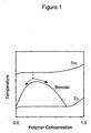
- Fig. 1 is a phase diagram of a typical liquid-liquid phase separation.
- the melting point Tm (°C) and the crystallization temperature Tc (°C) of the stock solution are determined at a heating/cooling rate of 10 °C/min by differential scanning calorimetry (DSC), unless otherwise specified.
- a binodal curve is obtained by plotting the phase separation temperatures that are determined by measuring clouding points. In the liquid-liquid phase separation, the binodal curve lies at a higher-temperature side than the crystallization curve.
- the polymer solution is gradually cooled from the melting point. When the polymer solution reaches any temperature on the binodal curve, the solution is separated into a concentrated polymer phase and a diluted polymer phase. The phase separation continues until the solution reaches the crystallization temperature.
- the final porous structure after removing the solvent is a matrix structure (sea-island structure), although the structure depends on the composition of the polymer solution and the cooling rate.
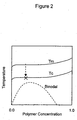
- Fig. 2 is a phase diagram of a typical solid-liquid phase separation.
- the crystallization curve lies at a higher-temperature side than the binodal curve.
- the polymer solution is gradually cooled from the melting point.
- crystallization of the polymer occurs.
- the polymer crystals grow.
- the final porous structure after removing the solvent is a spherulite structure, although the structure depends on the composition of the polymer solution and the cooling rate.
- any polyvinylidene fluoride/poor solvent system causes the solid-liquid phase separation.
- the binodal curve lies below the crystallization curve and is not observed.
- the relative position of the binodal curve shifts towards the high-temperature side as the affinity of the solvent to the polymer decreases.
- no solvent showing liquid-liquid phase separation is known.
- the crystallization temperature Tc is defined as follows: A mixture of a polyvinylidene fluoride resin and a solvent, the mixture having the same composition as that of a polymer stock solution for producing a membrane, is sealed into a DSC cell. The DSC cell is heated at a heating rate of 10 °C/min to a dissolution temperature in a DSC apparatus, is held at the dissolution temperature for 5 minutes, and is cooled at a cooling temperature of 10 °C/min. The rising temperature of the crystallization peak of the DSC curve in the cooling stage is defined as the crystallization temperature Tc (see Fig. 3).
- the crystallization temperature of the polymer solution is highly related to the membrane structure formed by the thermally induced phase separation.
- the present invention is characterized in that the crystallization temperature Tc of the polymer solution is in the range of 40°C to 120°C.
- the conditions for forming the membrane are controlled so that the crystallization temperature becomes higher.
- the membrane structure namely, the spherulite size can be miniaturized.
- a membrane having a fine structure exhibits high separability.
- Conditions affecting the crystallization temperature of the stock solution are, for example, the polymer concentration, types of polymer (molecular weight, shape of the branch, type of copolymer), the type of solvent, and additives affecting the crystallization.
- the crystallization temperature Tc increases while the spherulite size decreases.
- the inventors have also found that the spherulite size decreases as the crystallization temperature Tc increases.
- the spherulite size increases as the molecular weight of the polymer increases.
- the crystallization temperature Tc is less correlated with the molecular weight, but is affected by the type of polymer (homopolymer or copolymer) and the shape of the branch. With substantially the same molecular weight, the spherulite size tends to decrease when a polymer solution having a higher crystallization temperature Tc, which is determined by the shape of the branch and the type of copolymer, is used.
- the type of polymer is preferably selected so as to increase the polymer concentration and the crystallization temperature Tc of the polymer solution.
- the polymer stock solution preferably contains additives that can shift the crystallization temperature Tc of the stock solution, such as organic and inorganic salts.
- the results of X-ray diffractometry show the formation of the spherulite structure.
- the formation of the spherulites is an exothermic reaction.
- crystals that are first formed during the crystallization of polymers such as polyvinylidene fluoride resin are called primary nuclei.
- the primary nuclei grow into spherulites. If the formation rate of the primary nuclei is low, heat generated in the growth of the primary nuclei inhibits further formation of primary nuclei and facilitates further growth of the generated primary nuclei.
- the crystal growth continues until the spherulites collide with each other. Since the crystal growth is terminated by collision, the final spherulite size depends on the number of the primary nuclei generated first.
- the crystallization temperature Tc of the polymer solution is preferably in the range of 40°C to 120°C, more preferably 45°C to 105°C, and most preferably 48°C to 95°C.
- a crystallization temperature Tc of less than 40°C does not cause the formation of a fine membrane structure.
- a crystallization temperature exceeding 120°C causes crystallization of the polymer in the polymer solution; hence, equipment for forming the membrane, such as a dissolver and pipes, must be controlled at high temperatures, resulting in energy loss.
- the solution must be rapidly cooled from a high temperature to a crystallization temperature.
- the polymer concentration must be high otherwise a high-porosity membrane cannot be obtained.
- the polyvinylidene fluoride resin concentration in the polymer solution is preferably in the range of 20 to 60 percent by weight and more preferably 30 to 50 percent by weight, in view of compatibility between the mechanical strength and water permeability of the hollow fiber membrane, and formability into the hollow fiber membrane.
- a polymer concentration of less than 20 percent by weight causes a decrease in the crystallization temperature Tc of the polymer solution. Such a decrease inhibits the formation of a fine membrane structure.
- a polyvinylidene fluoride resin concentration in the range of 30 to 60 percent by weight facilitates production of a membrane having high permeability and a fine membrane structure.
- the weight average molecular weight of the polyvinylidene fluoride resin in the stock solution is preferably at least 2 ⁇ 10 5 .
- a weight average molecular weight of less than 2 ⁇ 10 5 leads to low viscosity of the solution that impairs formability of the membrane and a decrease in the mechanical strength of the membrane.
- a polymer having a high molecular weight causes an increase in viscosity of the solution, which inhibits the crystal growth. As a result, many spherulite nuclei, which are beneficial in the formation of a fine structure, are formed.
- the weight average molecular weight of the polyvinylidene fluoride resin is in the range of 3 ⁇ 10 5 to 3 ⁇ 10 6 .
- the polymer solution is discharged from a double pipe spinneret to form a hollow fiber membrane, and the hollow fiber membrane is cooled to obtain a gel product.
- the spinneret temperature Ts (°C) in the present invention represents the temperature of the bottom surface of the spinneret that discharges the polymer solution.
- the spinneret temperature Ts is controlled so as to satisfy the relationship Tc ⁇ Ts ⁇ Tc + 90, preferably Tc + 10 ⁇ Ts ⁇ Tc + 85, and more preferably Tc + 20 ⁇ Ts ⁇ Tc + 80.
- the crystallization temperature Tc is preferably as low as possible for cooling efficiency; however, an excessively low crystallization temperature Tc impairs the formability of the membrane.
- the polymer is crystallized at the spinneret and cannot be satisfactorily discharged. If the spinneret temperature Ts is larger than the crystallization temperature Tc + 90°C, the resulting membrane retaining heat is insufficiently cooled during the cooling step and a fine membrane structure is not obtained.
- the polymer solution is discharged through a double pipe spinneret for spinning a hollow fiber membrane, and the spun hollow fiber membrane is introduced to a drying section having a predetermined length and to a cooling bath to coagulate the hollow fiber membrane.
- the polymer solution is preferably filtered through a 5 to 100 ⁇ m stainless-steel filter.
- the dimensions of the spinneret are determined in view of the size and structure of the hollow fiber membrane.
- the spinneret has a slit outer diameter of 0.7 to 10 mm, a slit inner diameter of 0.5 to 4 mm, and an injection pipe of 0.25 to 2 mm.
- the spinning draft (the drawing rate to the linear discharged rate of the stock solution at the spinneret) is preferably in the range of 0.8 to 100, more preferably 0.9 to 50, and most preferably 1 to 30, and the distance between the spinneret surface and the cooling bath surface is preferably in the range of 10 to 1,000 mm.
- the spinneret temperature Ts may be different from the dissolution temperature. Preferably, the dissolution temperature is higher than the spinneret temperature Ts for rapidly completing uniform dissolution.
- the hollow fiber polymer is coagulated into a hollow fiber membrane, as described above.
- the coagulation bath containing a poor solvent has a temperature in the range of 0°C to 50°C and more preferably 5°C to 30°C and a poor solvent concentration in the range of 60 to 100 percent by weight and more preferably 75 to 90 percent by weight.
- the coagulation bath may contain two or more poor solvents in combination.
- the coagulation bath may contain any good solvent and nonsolvent within the above poor solvent concentration. Rapid cooling with a large temperature difference between the polymer solution temperature and the polymer dissolution temperature facilitates the formation of fine spherulite structures that are bonded by the coagulated polymer, forming a membrane structure having high permeability and high tensile properties.
- a poor solvent contained in the cooling bath at a considerably high concentration suppresses nonsolvent-induced phase separation, and the resulting hollow fiber membrane does not have a dense layer on the surface. If the cooling bath contains a high concentration of nonsolvent such as water, the resulting membrane has a dense surface layer and does not exhibit water permeability even after the membrane is stretched.
- the polymer solution is discharged while gas or liquid is being supplied into the hollow section of the inner tube of the spinneret.
- a hollow section-forming liquid containing 60 to 100 percent by weight of a poor solvent is preferably supplied.
- the content of the poor solvent is more preferably in the range of 70 to 100 percent by weight and most preferably 80 to 100 percent by weight.
- the liquid containing a high amount of poor solvent suppresses nonsolvent-induced phase separation and facilitates the formation of fine spherical structures. Different poor solvents may be used in combination.
- the liquid may contain small amounts of a good solvent and/or nonsolvent within the above range.
- the cooling bath and the hollow section-forming liquid may be the same or different, and may be appropriately selected according to the target properties of the hollow fiber membrane. If the same poor solvent is used in the polymer solution, the cooling bath, and the hollow section-forming liquid, the poor solvent can be easily recovered. Any vessel may be used for containing the cooling bath.
- the cooling bath may be circulated or renewed while the composition and temperature are being controlled.
- a cooling liquid may be circulated in a pipe in which the hollow fiber membrane travels, or may be sprayed onto the hollow fiber membrane that travels through air.
- the polymer solution is cooled at an average cooling rate Vt in the range of 2 ⁇ 10 3 °C/min to 10 6 °C/min when the polymer solution is cooled to the crystallization temperature Tc.
- the average cooling rate Vt is preferably in the range of 5 ⁇ 10 3 °C/min to 6 ⁇ 10 5 °C/min and more preferably 10 4 °C/min to 3 ⁇ 10 5 °C/min.
- the average cooling rate Vt during the formation of the membrane in the present invention is determined by either of the following methods (a) and (b):
- the time to reach the crystallization temperature Tc in air can be measured, for example, by thermography, and the elapsed time t(sc) is calculated from the distance from the spinneret to a point when the solution reaches the crystallization temperature Tc and the spinning rate.
- Vt (Ts - Ta)/t(sa) wherein Ts is the temperature (°C) of the spinneret, Ta is the temperature (°C) of the cooling bath, and t(sa) is the elapsed time from discharging the stock solution to reaching the temperature of the cooling bath.
- the polymer solution is assumed to reach the temperature of the cooling bath immediately after the polymer solution is dipped into the cooling bath.
- the elapsed time t(sa) can be calculated from the distance from the spinneret to the cooling bath and the forming rate of the membrane.
- An average cooling rate of less than 2 ⁇ 10 3 °C/min inevitably causes the formation of large structures that do not show satisfactory permeability.
- An average cooling rate exceeding 10 6 °C/min requires a significantly high cooling rate.
- the reason for a fine structure being obtained by a high cooling rate when the temperature of the cooled polymer solution reaches the crystallization temperature Tc is as follows: Heat generated by the formation of primary nuclei during the cooling step is removed by rapid cooling; crystal growth is inhibited and many primary nuclei suitable for forming fine structures are simultaneously formed.
- the finely porous membrane obtained by the above method has a structure of fine bonded spherulites and pores therebetween. This membrane has higher mechanical strength, higher water permeability, and higher separability than conventional fine porous membranes.
- the cooled gel membrane is dipped into an extraction solvent or is dried to remove the solvent from the membrane.
- a porous membrane is thereby prepared.
- the porous membrane may be drawn to increase porosity and to decrease the pore diameter due to elongation or tearing at the interfaces between the spherulites, and to enhance the mechanical strength due to orientation of the membrane.
- the drawing temperature is preferably in the range of 50°C to 140°C, more preferably 55°C to 120°C, and most preferably 60°C to 100°C, while the drawing ratio is preferably in the range of 1.1 to 5 times, more preferably 1.1 to 4 times, and most preferably 1.1 to 3 times.
- the porous membrane cannot be uniformly drawn at a temperature below 50°C and will be structurally damaged at weak portions.
- parts of the spherical structures and the polymer molecules connecting the spherical structures are uniformly drawn at a temperature in the range of 50°C to 140°C.
- many fine long pores having high stretch properties and water permeability are formed.
- the membrane is drawn at a temperature exceeding 140°C, which is near the melting point of the polyvinylidene fluoride resin, the spherical structures are melted and the formation of fine pores is inhibited.
- the water permeability is not improved.
- drawing is performed in a liquid because of ease of temperature control; however, drawing may be performed in gas such as steam.
- the liquid is preferably water. In drawing at a temperature of 90°C or more, low-molecular weight polyethylene glycol may be used instead of water. Alternatively, drawing may be performed in a mixture of different liquids, for example, water and polyethylene glycol.
- drawing may be employed depending on the desired application of the hollow fiber membrane.
- Fig. 4 is an electron micrograph of a cross-section of the hollow fiber membrane according to the present invention.
- the hollow fiber membrane has spherical structures having an average diameter in the range of 0.3 to 30 ⁇ m, preferably 0.5 to 20 ⁇ m, and more preferably 0.8 to 10 ⁇ m.
- the interior of the hollow fiber membrane has spherical structures.
- the spherical structures are bonded and have pores therebetween.
- the mechanical strength and water permeability are higher than those of conventional network structures.
- the interior includes the substantial inner portion and/or the inner surface of the hollow fiber membrane but excludes the outer surface.
- the diameter of the spherical structures is determined by averaging the diameters of at least 10, and preferably at least 20 spherical structures selected at random in a scanning electron micrograph at a magnification that can clearly observe a cross section and/or an inner surface of the hollow fiber membrane.
- the photograph may be analyzed using an image analyzer to determine equivalent circular diameters of the images.
- the density of the spherical structure is preferably in the range of 10 3 to 10 8 /mm 2 and more preferably 10 4 to 10 6 /mm 2 .
- the density is determined by counting the number of spherical structures in a unit area in the micrograph.
- the spherical structures are substantially spherical or oval, and the circularity (short diameter/long diameter) is preferably at least 0.5, more preferably at least 0.6, and most preferably at least 0.7.
- the hollow fiber membrane according to the present invention has fine pores having an average diameter in the range of 0.01 to 20 ⁇ m, more preferably 0.01 to 10 ⁇ m, and most preferably 0.01 to 5 ⁇ m in the outer surface.
- the pores in the outer surface may have any suitable shape.
- the average of the equivalent circular diameters of these pores is preferably determined from the photograph using an image analyzer. Alternatively, the average of the equivalent circular diameters may be determined by averaging the short diameter and long diameter averages of the observed pores.
- the spherical structure is preferably observed at the inner portion of a cut section of the hollow fiber membrane.
- the outer diameter and the thickness of the hollow fiber membrane may be determined depending on the target volume of the permeable water in a membrane module, in view of the pressure loss in the longitudinal direction inside the hollow fiber membrane, as long as the hollow fiber membrane has predetermined mechanical strength.
- a larger outer diameter is advantageous for pressure loss but disadvantageous for the membrane area due to a reduction in the number of packed hollow fiber membranes.
- a smaller outer diameter is advantageous for the membrane area due to an increase in the number of packed membranes but disadvantageous for pressure loss.
- a smaller thickness is preferable as long as the mechanical strength is maintained.
- the outer diameter of the hollow fiber membrane is preferably in the range of 0.3 to 3 mm, more preferably 0.4 to 2.5 mm, and most preferably 0.5 to 2 mm.
- the thickness is preferably 0.08 to 0.4 times, more preferably 0.1 to 0.35 times, and most preferably 0.12 to 0.3 times the outer diameter.
- the hollow fiber membrane of the present invention does not substantially have macrovoids.
- macrovoids represent voids having a diameter of 50 ⁇ m or more.
- the number of macrovoids is preferably 10/mm 2 and more preferably 5/mm 2 , and most preferably zero.
- the hollow fiber membrane of the present invention has a water permeability in the range of 0.1 to 10 m 3 /m 2 ⁇ hr, more preferably 0.5 to 9 m 3 /m 2 ⁇ hr, and most preferably 1 to 8 m 3 /m 2 ⁇ hr at 100 kPa and 25°C, has a tensile strength in the range of 0.3 to 3 kg per fiber, more preferably 0.4 to 2.5 kg per fiber, and most preferably 0.5 to 2 kg per fiber, and has an elongation at break in the range of 20% to 1,000%, more preferably 40% to 800%, and most preferably 60% to 500%.
- a hollow fiber membrane satisfying these ranges exhibits high water permeability without being damaged under usual operating conditions.
- the polyvinylidene fluoride main chain preferably has hydrophilic functional groups.
- the hydrophobic polyvinylidene fluoride resin easily traps contaminants in water, resulting in decreased water permeability. Furthermore, the trapped contaminants cannot be easily removed by washing. Introduction of the hydrophilic groups prevents the trapping of the contaminants and facilitates their removal by washing. As a result, the filtration membrane has a prolonged operation life. Examples of hydrophilic groups are hydroxyl, amino, and carboxyl. These hydrophilic groups may be introduced alone or in combination.
- hydrophilic groups decreases the mechanical strength of the hollow fiber membrane, a small number that cannot be determined by general analytical methods is introduced on the inner and outer surfaces and the surfaces of the porous structures of the hollow fiber membrane.
- introduction of the hydrophilic groups can be evaluated by an increase in the water penetration rate.
- the hydrophilic functional groups can be introduced by any known process.
- methods for introducing hydroxyl groups are a reaction of a polyoxyalkylene having hydroxyl end groups in the presence of base disclosed in Japanese Unexamined Patent Application Publication No. 53-80378; a chemical treatment in a strong alkaline solution containing an oxidizing agent disclosed in Japanese Unexamined Patent Application Publication No. 63-172745; and grafting of a monomer containing a neutral hydroxyl group disclosed in Japanese Unexamined Patent Application Publication No. 62-258711.
- a more preferred method in the present invention is dehydrofluorination of a hollow fiber membrane in an aqueous alkaline solution and then treatment of the membrane in an aqueous solution containing an oxidizing agent.
- This method has an advantage in that the process can be performed in a diluted alkaline solution and a diluted oxidizing agent solution, whereas the method disclosed in Japanese Unexamined Patent Application Publication No. 63-172745, which uses an oxidizing agent in the presence of strong alkaline, requires a large amount of strong oxidizing agent, i.e., permanganate or bichromate, and treatment of waste water containing heavy metal ions, although hydroxyl groups are infallibly introduced.
- the dehydrofluorination method can be achieved in a 0.001- to 1-N aqueous alkaline solution in combination with hydrogen oxide or hypochlorite as the oxidizing agent.
- Examples of usable alkalis are inorganic hydroxides, i.e.
- the hollow fiber membrane may be treated with an alkali followed by oxidation in ozone-containing water, as is disclosed in Japanese Unexamined Patent Application Publication No. 5-317663.
- Examples of reactions for introducing amino groups are reaction of compounds containing primary or secondary amino groups disclosed in Japanese Unexamined Patent Application Publication Nos. 59-169512 and 1-224002.
- the hollow fiber membrane is immersed into an alcohol or aqueous alcohol before the introduction of the hydrophilic functional groups in order to introduce these groups homogeneously.
- alcohols are methanol, ethanol, 1-propanol, 2-propanol, 1-butanol, 2-butanol, isobutyl alcohol, and t-butyl alcohol.
- the alcohol content in the aqueous alcohol is preferably at least 10 percent by weight, more preferably at least 20 percent by weight, and most preferably at least 30 percent by weight.
- the hollow fiber membrane produced by the above method may be used in hollow fiber membrane modules that collect permeated water.
- One type of module is a cylindrical container containing a bundle of hollow fiber membranes, an end or two ends of the bundle being fixed with an epoxy resin or the like.
- Another type of module includes hollow fiber membranes arranged in a flat plate, two ends of the hollow fiber membranes being fixed.
- the hollow fiber membrane module is generally provided with a compression means, i.e., a pump or a difference in water level, at an end for supplying raw water, or a suction means, i.e., a pump or siphon at the other end for collecting the permeated water.
- the hollow fiber microfiltration membrane is thereby used as a water separating apparatus that produces purified permeated water from raw water by membrane filtration.
- raw water represents river water, lake water, ground water, seawater, waste water, discharged water, and treated water thereof.
- the membrane is preferably brought into contact with chlorine in an amount corresponding to the organic content in the raw water.
- the inventors found that the polyvinylidene fluoride membrane must be brought into contact with chlorine at a prescribed time interval during the filtration operation to ensure normal operation.
- the inventors also found that the amount of chlorine in contact with the membrane is closely connected to the organic content in the supplied raw water. It is known that natural organic matter such as fumic substances in raw water function as fouling substances for membranes (Water Science and Technology: Water Supply Vol. 1, No. 4, pp. 40-56).
- Chlorine is believed to prevent trapping of the organic matter on the membrane, decompose the trapped organic matter, and facilitate detachment of the trapped organic matter from the membrane.
- the hydrophobic polyvinylidene fluoride resin membrane easily causes fouling compared with hydrophilic membranes.
- the above chlorine treatment is effective for preventing fouling of the membrane.
- fouling will easily occur on the uneven surface and micropores; thus, such chlorine treatment is effective for preventing fouling.
- an excess amount of chlorine causes economic and health problems such as formation of trihalomethanes, although it ensures stable operation.
- the chlorine content is preferably a minimum corresponding to the organic content in the raw water.
- the organic content in the water may be determined by various processes, such as total organic carbon (TOC), chemical oxygen demand (COD), biochemical oxygen demand (BOD), potassium permanganate consumption, and UV absorbance at 260 nm.
- TOC total organic carbon
- COD chemical oxygen demand
- BOD biochemical oxygen demand
- UV absorbance at 260 nm.
- highly precise and convenient TOC is preferred.
- the amount of chlorine dosing C (mg/l ⁇ min) is 0.01 to 10 times and preferably 0.03 to 5 times the TOC (mg/l) in the raw water supplied for each minute.
- the TOC represents an average TOC in the raw water and is determined by a statistical method in view of seasonal and daily variations. Chlorine can be brought into contact with the membrane by various methods:
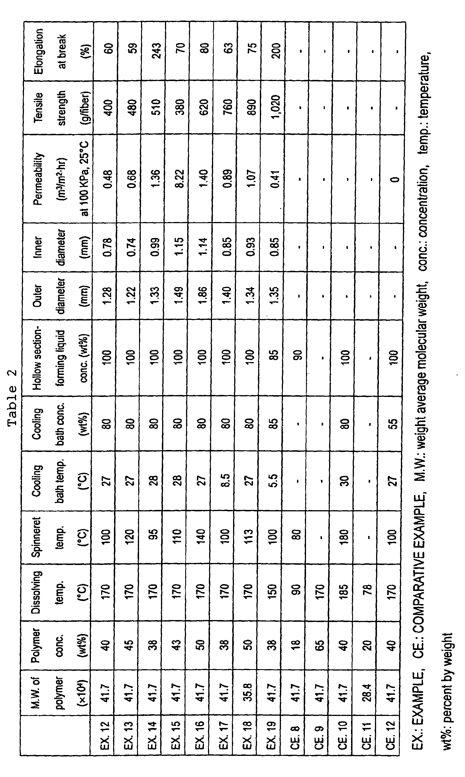
- Vinylidene fluoride homopolymer was used as the polymer according to the present invention, cyclohexanone was used as the poor solvent, and an aqueous cyclohexanone solution was used as the hollow section-forming liquid, and the cooling bath.
- each polymer having a prescribed weight average molecular weight was dissolved into the poor solvent at a given temperature to prepare a polymer solution having a polymer concentration shown in Table 1.
- the resulting hollow fiber membrane had no spherical structure and thus did not show permeability.
- the permeability after stretching was at most 0.2 m 3 /m 2 ⁇ hr at a differential pressure of 100 kPa and 25°C. Furthermore, the membrane was not able to be stretched uniformly and was easily broken during the drawing step.
- COMPARATIVE EXAMPLE 4 the polymer was dissolved for 12 hours, but no uniform solution was obtained. This solution was gelated when placed into a hopper of the spinning machine, and no hollow fiber membrane was obtained.
- the hollow fiber membrane prepared in EXAMPLE 1 was drawn to 2.0 times in water at 88°C.
- the stretched hollow fiber membrane had an outer diameter of 1.55 mm, an inner diameter of 0.95 mm, a permeability of 1.9 m 3 /m 2 ⁇ hr at a differential pressure of 100 kPa and 25°C, a tensile strength of 880 g/fiber, and an elongation at break of 55%.
- the hollow fiber membrane prepared in EXAMPLE 2 was drawn to 2.5 times in polyethylene glycol (molecular weight: 400) at 110°C.
- the stretched hollow fiber membrane had an outer diameter of 1.40 mm, an inner diameter of 0.90 mm, a permeability of 2.5 m 3 /m 2 ⁇ hr at a differential pressure of 100 kPa and 25°C, a tensile strength of 1,250 g/fiber, and an elongation at break of 50%.
- the hollow fiber membrane prepared in EXAMPLE 3 was drawn to 3.0 times in water at 85°C.
- the stretched hollow fiber membrane had an outer diameter of 1.30 mm, an inner diameter of 0.75 mm, a permeability of 3.6 m 3 /m 2 ⁇ hr at a differential pressure of 100 kPa and 25°C, a tensile strength of 1,720 g/fiber, and an elongation at break of 48%.
- the hollow fiber membrane prepared in EXAMPLE 4 was drawn to 3.5 times in water at 85°C.
- the stretched hollow fiber membrane had an outer diameter of 1.20 mm, an inner diameter of 0.70 mm, a permeability of 4.8 m 3 /m 2 ⁇ hr at a differential pressure of 100 kPa and 25°C, a tensile strength of 610 g/fiber, and an elongation at break of 50%.
- the hollow fiber membrane prepared in EXAMPLE 5 was drawn to 4.0 times in water at 85°C.
- the stretched hollow fiber membrane had an outer diameter of 1.35 mm, an inner diameter of 0.80 mm, a permeability of 2.1 m 3 /m 2 ⁇ hr at a differential pressure of 100 kPa and 25°C, a tensile strength of 1,380 g/fiber, and an elongation at break of 45%.
- cyclohexane Into 60 percent by weight of cyclohexane, 30 percent by weight of polyvinylidene fluoride homopolymer having a weight average molecular weight of 358,000 and 10 percent by weight of tetrafluoroethylene/vinylidene fluoride copolymer were dissolved at 165°C.
- the polymer solution was discharged from a spinneret at 145°C while 100% cyclohexanone (hollow section-forming liquid) was being discharged into the hollow section of the inner tube of the spinneret, and was solidified in a cooling bath containing 90 percent by weight of cyclohexanone at 30°C.
- the fiber was drawn to 3.0 times in water at 80°C.
- the stretched hollow fiber membrane had an outer diameter of 1.40 mm, an inner diameter of 0.90 mm, a permeability of 1.5 m 3 /m 2 ⁇ hr at a differential pressure of 100 kPa and 25°C, a tensile strength of 1,580 g/fiber, and an elongation at break of 55%.
- the hollow fiber membrane prepared in EXAMPLE 3 was drawn in water at 45°C, but broke at many portions. Furthermore, the successfully stretched portions showed leakage of matter that should have been collected.
- the hollow fiber membrane prepared in EXAMPLE 3 was drawn to 2.5 times in polyethylene glycol (molecular weight: 400) at 150°C.
- the stretched hollow fiber membrane had a low permeability of 0.5 m 3 /m 2 ⁇ hr at a differential pressure of 100 kPa and 25°C because of deformation caused by melting of the micropores.
- the hollow fiber membrane prepared in EXAMPLE 3 was drawn to 5.5 times in water at 85°C.
- the stretched hollow fiber membrane had an outer diameter of 1.05 mm, an inner diameter of 0.65 mm, a permeability of 0.8 m 3 /m 2 ⁇ hr at a differential pressure of 100 kPa and 25°C, a tensile strength of 1,860 g/fiber, and an elongation at break of 32%.
- the permeability was low because the micropores had a small diameter.
- the resulting hollow fiber membrane had no clear spherical structures and thus did not show high permeability.
- the permeability after stretching was at most 0.4 m 3 /m 2 ⁇ hr at a differential pressure of 100 kPa and 25°C.
- COMPARATIVE EXAMPLE 11 the polymer was dissolved for 12 hours as in COMPARATIVE EXAMPLE 4, but no uniform solution was obtained. This solution was gelated when placed into a hopper of the spinning machine, and no hollow fiber membrane was obtained.
- the hollow fiber membrane prepared in EXAMPLE 12 was drawn to 2.2 times in water at 80°C.
- the stretched hollow fiber membrane had an outer diameter of 1.07 mm, an inner diameter of 0.64 mm, a permeability of 1.7 m 3 /m 2 ⁇ hr at a differential pressure of 100 kPa and 25°C, a tensile strength of 520 g/fiber, and an elongation at break of 46%.
- the hollow fiber membrane prepared in EXAMPLE 13 was drawn to 1.6 times in water at 80°C.
- the stretched hollow fiber membrane had an outer diameter of 1.16 mm, an inner diameter of 0.68 mm, a permeability of 3.4 m 3 /m 2 ⁇ hr at a differential pressure of 100 kPa and 25°C, a tensile strength of 690 g/fiber, and an elongation at break of 41%.
- the hollow fiber membrane prepared in EXAMPLE 14 was drawn to 1.7 times in water at 81°C.
- the stretched hollow fiber membrane had an outer diameter of 1.13 mm, an inner diameter of 0.81 mm, a permeability of 1.7 m 3 /m 2 ⁇ hr at a differential pressure of 100 kPa and 25°C, a tensile strength of 730 g/fiber, and an elongation at break of 189%.
- the hollow fiber membrane prepared in EXAMPLE 15 was drawn to 1.5 times in water at 80°C.
- the stretched hollow fiber membrane had an outer diameter of 1.43 mm, an inner diameter of 1.07 mm, a permeability of 10.0 m 3 /m 2 ⁇ hr at a differential pressure of 100 kPa and 25°C, a tensile strength of 520 g/fiber, and an elongation at break of 46%.
- the hollow fiber membrane prepared in EXAMPLE 16 was drawn to 1.9 times in water at 87°C.
- the stretched hollow fiber membrane had an outer diameter of 1.49 mm, an inner diameter of 0.93 mm, a permeability of 2.7 m 3 /m 2 ⁇ hr at a differential pressure of 100 kPa and 25°C, a tensile strength of 820 g/fiber, and an elongation at break of 56%.
- the hollow fiber membrane prepared in EXAMPLE 19 was drawn to 1.5 times in water at 87°C.
- the stretched hollow fiber membrane had an outer diameter of 1.31 mm, an inner diameter of 0.79 mm, a permeability of 2.6 m 3 /m 2 ⁇ hr at a differential pressure of 100 kPa and 25°C, a tensile strength of 1,020 g/fiber, and an elongation at break of 130%.
- the hollow fiber membrane prepared in EXAMPLE 12 was drawn in water at 45°C. The membrane broke at many portions during the drawing step. The successfully stretched portions of the hollow fiber membrane did not show high permeability.
- the hollow fiber membrane prepared in EXAMPLE 12 was drawn to 3.0 times in polyethylene glycol (molecular weight: 400) at 150°C.
- the stretched hollow fiber membrane had a low permeability of 0.3 m 3 /m 2 ⁇ hr at a differential pressure of 100 kPa and 25°C because of deformation caused by melting of the micropores.
- the hollow fiber membrane prepared in EXAMPLE 12 was drawn to 5.5 times in water at 85°C.
- the stretched hollow fiber membrane had an outer diameter of 1.00 mm, an inner diameter of 0.60 mm, a permeability of 0.29 m 3 /m 2 ⁇ hr at a differential pressure of 100 kPa and 25°C, a tensile strength of 1,560 g/fiber, and an elongation at break of 29%.
- the permeability was low because the micropores had a small diameter.
- the stretched hollow fiber membrane had an outer diameter of 1.40 mm, an inner diameter of 0.90 mm, a permeability of 2.8 m 3 /m 2 ⁇ hr at a differential pressure of 100 kPa and 25°C, a tensile strength of 1,010 g/fiber, and an elongation at break of 54%.
- polyvinylidene fluoride homopolymer having a weight average molecular weight of 417,000 was dissolved at 165°C.
- the polymer solution was discharged from a spinneret at 110°C while a hollow section-forming liquid of 60 percent by weight of dimethyl phthalate and 40 percent by weight of ethylene glycol (molecular weight: 400) was being discharged into the hollow section of the inner tube of the spinneret, and was solidified in a cooling bath containing 60 percent by weight of dimethyl phthalate and 40 percent by weight of ethylene glycol (molecular weight: 400) at 40°C.
- the fiber was drawn to 3.0 times in ethylene glycol (molecular weight: 400) at 120°C.
- the stretched hollow fiber membrane had an outer diameter of 1.35 mm, an inner diameter of 0.75 mm, a permeability of 1.8 m 3 /m 2 ⁇ hr at a differential pressure of 100 kPa and 25°C, a tensile strength of 1,410 g/fiber, and an elongation at break of 38%.
- ⁇ -butyrolactone Into 60 percent by weight of ⁇ -butyrolactone, 40 percent by weight of polyvinylidene fluoride homopolymer having a weight average molecular weight of 417,000 was dissolved at 150°C to prepare a homogeneous solution.
- the solution had a crystallization temperature Tc of 57°C.
- Tc crystallization temperature
- the preferable discharge temperature lies within the range 57°C ⁇ Ts ⁇ 147°C.
- the polymer solution was allowed to stand at 110°C for defoaming and was discharged at 100°C (spinneret temperature Ts) from the outer pipe of a double pipe spinneret, while 100 percent by weight of ⁇ -butyrolactone was being supplied into the hollow section from the inner tube of the double pipe spinneret.
- the solution was discharged into a cooling bath at 5°C having a distance between the spinneret surface and the cooling bath surface of 4 cm and containing 80 percent by weight of ⁇ -butyrolactone and 20 percent by weight of water at an extruding rate of 6.0 m/min and an average cooling rate of 14,250 °C/min to allow the solution to gelate in the cooling bath.
- the resultant extrudate was drawn to 1.5 times in a hot water bath at 80°C to prepare a hollow fiber membrane.
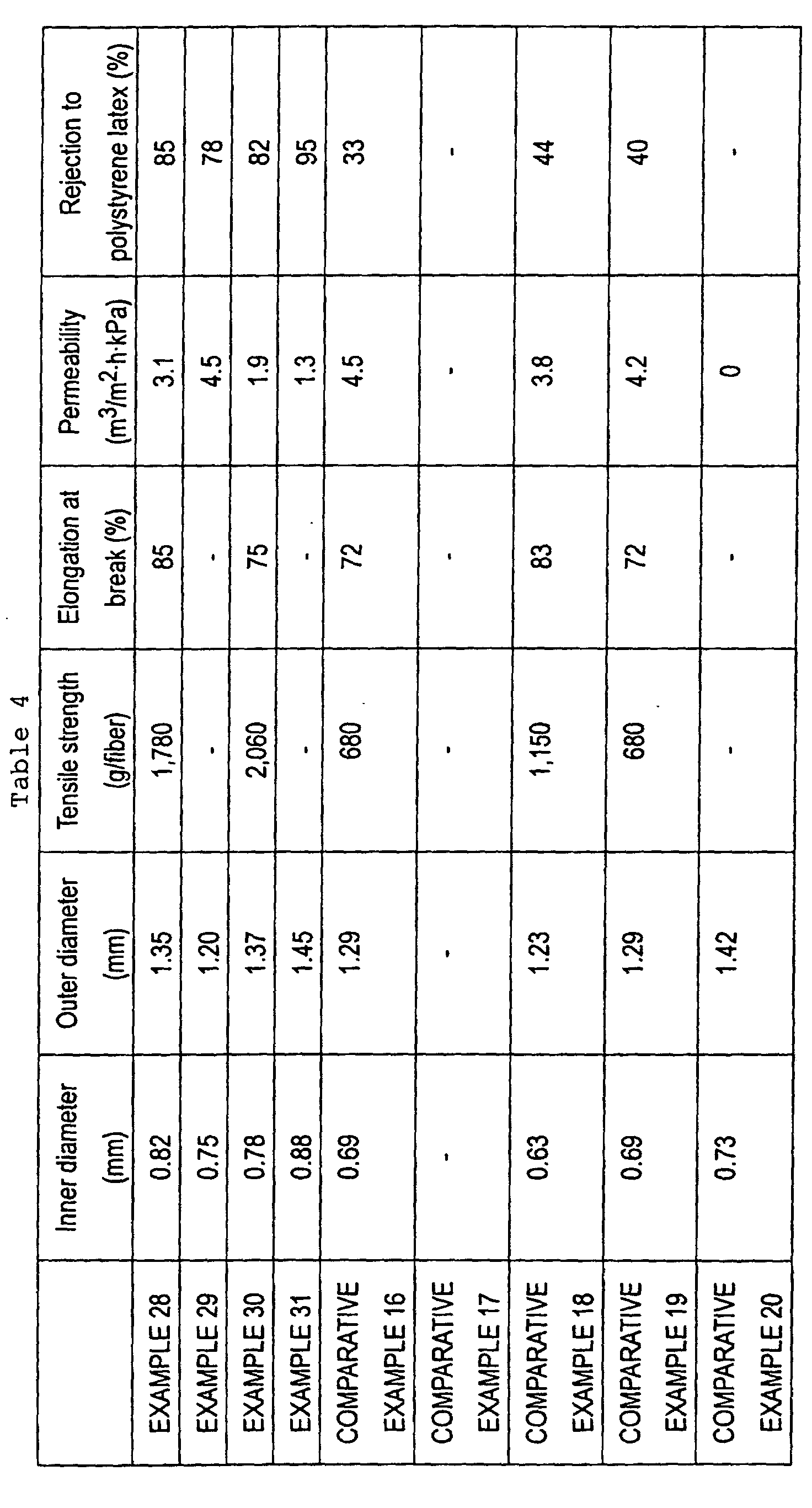
- the properties of the hollow fiber membrane are shown in Table 4.
- the hollow fiber membrane was excellent in mechanical strength, permeability, and separability.
- the membrane had a structure of integrated spherulites having a particle size of 1.8 ⁇ m with pores extending between the spherulites.
- a hollow fiber membrane was prepared as in EXAMPLE 1 according to conditions shown in Table 3. A liquid mixture of 90 percent by weight of ⁇ -butyrolactone and 10 percent by weight of water was supplied into the hollow section. The properties of the hollow fiber membrane are shown in Table 4. The hollow fiber membrane was excellent in permeability and separability.
- the membrane had a structure of integrated spherulites having a particle size of 3.2 ⁇ m with pores extending between the spherulites.
- a hollow fiber membrane was prepared as in EXAMPLE 1 according to conditions shown in Table 3, wherein propylene carbonate was supplied into the hollow section and was also used in the cooling bath. The properties of the hollow fiber membrane are shown in Table 4.
- the hollow fiber membrane was excellent in mechanical strength, permeability, and separability.
- the membrane had a structure of integrated spherulites having a particle size of 1.9 ⁇ m with pores extending between the spherulites.
- a hollow fiber membrane was prepared as in EXAMPLE 3 according to conditions shown in Table 3. The thermographic results showed that the hollow fiber was cooled to 79°C or less at a position 3 cm below the spinneret, and the calculated average cooling rate Vt in the membrane-forming step according to method (a) was 3,500 °C/min.
- the properties of the hollow fiber membrane are shown in Table 4.
- the hollow fiber membrane was excellent in permeability and separability.
- the membrane had a structure of integrated spherulites having a particle size of 2.2 ⁇ m with pores extending between the spherulites.
- a hollow fiber membrane was prepared as in COMPARATIVE EXAMPLE 28 according to conditions shown in Table 3. The results are shown in Table 4. The hollow fiber membrane showed a small rejection of 33% to uniform polystyrene latex particles having a diameter of 0.309 ⁇ m.
- the membrane had a structure of integrated spherulites having a particle size of 4.3 ⁇ m with pores extending between the spherulites.
- a small average cooling rate is assumed to increase the particle size of the spherulites and thus to decrease the filterability due to an increased pore size.
- a hollow fiber membrane was prepared as in EXAMPLE 28 except that the spinneret temperature Ts was 150°C.
- the properties of the hollow fiber membrane are shown in Table 4.
- the hollow fiber membrane showed a small rejection of 44% to uniform polystyrene latex particles having a diameter of 0.309 ⁇ m.
- the membrane had a structure of integrated spherulites having a particle size of 5.1 ⁇ m with pores extending between the spherulites.
- a hollow fiber membrane was prepared as in COMPARATIVE EXAMPLE 28 according to conditions shown in Table 3. The properties of the hollow fiber membrane are shown in Table 4.
- the hollow fiber membrane showed a small rejection of 40% to uniform polystyrene latex particles having a diameter of 0.309 ⁇ m.
- the membrane had a structure of integrated spherulites having a particle size of 4.3 ⁇ m with pores extending between the spherulites.
- a hollow fiber membrane was prepared as in COMPARATIVE EXAMPLE 28 according to conditions shown in Table 3. The properties of the hollow fiber membrane are shown in Table 4. The hollow fiber membrane showed no water permeability (0 m 3 /m 2 ⁇ hr at a differential pressure of 100 kPa and 25°C).
- the hollow fiber membrane prepared in EXAMPLE 25 was immersed into an aqueous 50 weight percent ethanol solution and then into reverse osmosis (RO) water.
- the hollow fiber membrane was allowed to stand in an aqueous 0.01-N sodium hydroxide solution at 30°C for 1 hour, then was washed with RO water.
- the membrane was allowed to stand in an aqueous 1.5 weight percent hydrogen peroxide solution at 30°C for 1 hour, and was washed with RO water.
- the water permeability of the treated hollow fiber membrane increased to 3.2 m 3 /m 2 ⁇ hr at a differential pressure of 100 kPa and 25°C.
- the tensile strength was 1,100 g/fiber and the elongation at break was 125%.
- the hollow fiber membrane prepared in EXAMPLE 25 was immersed into an aqueous 50 weight percent ethanol solution and then into RO water.
- the hollow fiber membrane was allowed to stand in an aqueous 0.01-N sodium hydroxide solution at 30°C for 1 hour, then was washed with RO water.
- the membrane was allowed to stand in water containing 10-ppm ozone 100 hour.
- the water permeability of the treated hollow fiber membrane increased to 3.5 m 3 /m 2 ⁇ hr at a differential pressure of 100 kPa and 25°C.
- the tensile strength was 1,000 g/fiber and the elongation at break was 110%.
- the hollow fiber membrane prepared in EXAMPLE 25 was immersed into an 10 weight percent N-N,-dimethyl-1,3-propanediamine in ethanol solution at 30°C for 1 hour.
- the water permeability of the treated hollow fiber membrane significantly increased to 4.1 m 3 /m 2 ⁇ hr at a differential pressure of 100 kPa and 25°C.
- the tensile strength was 1,300 g/fiber and the elongation at break was 75%.
- Lake Biwa water was filtered by dead end filtration at a constant flow rate.
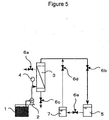
- Fig. 5 is a schematic diagram of a membrane separation apparatus used. Lake Biwa water during the filtration operation had an average turbidity of 6.8 NTU and an average TOC of 2.3 mg/l.
- a sodium hypochlorite solution at a concentration of 5 mg/l (0.07 times the average TOC of the raw water) was added to the back washing water.
- air was introduced from the bottom of the separation membrane module 3 to vibrate the hollow fiber membrane.
- an electromagnetic valve 6c was opened to drain dirty water in the separation membrane module 3.
- An electromagnetic valve 6b was closed during the physical washing operation.
- the filtration differential pressure after 1,000-hour operation was about 60 kPa, which was a low level.
- a filtration operation was performed at the same time as in EXAMPLE 35 except that the hollow fiber membrane prepared in EXAMPLE 25 was used.
- the filtration differential pressure after 1,000-hour operation was about 95 kPa, which was higher than that in EXAMPLE 35 and was a disadvantageous level in view of operation stability and cost.
- a filtration operation was performed at the same time as in EXAMPLE 35 except that no sodium hypochlorite was added.
- the filtration differential pressure reached 100 kPa in a day, and the apparatus was not able to continue the operation.
Landscapes
- Chemical & Material Sciences (AREA)
- Chemical Kinetics & Catalysis (AREA)
- Engineering & Computer Science (AREA)
- Manufacturing & Machinery (AREA)
- Water Supply & Treatment (AREA)
- Inorganic Chemistry (AREA)
- Dispersion Chemistry (AREA)
- Health & Medical Sciences (AREA)
- Transplantation (AREA)
- Organic Chemistry (AREA)
- Life Sciences & Earth Sciences (AREA)
- Physics & Mathematics (AREA)
- Hydrology & Water Resources (AREA)
- Environmental & Geological Engineering (AREA)
- Thermal Sciences (AREA)
- Materials Engineering (AREA)
- Medicinal Chemistry (AREA)
- Polymers & Plastics (AREA)
- Separation Using Semi-Permeable Membranes (AREA)
- Artificial Filaments (AREA)
- Spinning Methods And Devices For Manufacturing Artificial Fibers (AREA)
Abstract
Description
Case (b): the temperature of the cooled polymer solution reaches the crystallization temperature Tc in the cooling bath.


Claims (20)
- A method of producing a hollow fiber membrane comprising:discharging a polyvinylidene fluoride solution comprising a polyvinylidene fluoride resin and a poor solvent at a temperature above a phase separation temperature into a cooling bath at a temperature below the phase separation temperature to coagulate the polyvinylidene fluoride resin.
- The method according to claim 1, wherein the crystallization temperature of the polyvinylidene fluoride solution is in the range of 40°C to 120°C, the average cooling rate of the polyvinylidene fluoride solution when the temperature of the polyvinylidene fluoride solution reaches the crystallization temperature during cooling is in the range of 2×10³ °C/min to 106 °C/min, and the temperature Ts of a spinneret for discharging the polyvinylidene fluoride solution into the cooling bath and the crystallization temperature Tc satisfy the relationship Tc ≤ Ts ≤ Tc + 90.
- The method according to claim 1, wherein the polyvinylidene fluoride solution contains at least 20 to 60 percent by weight of the polyvinylidene fluoride resin.
- The method according to claim 1, wherein the polyvinylidene fluoride solution has a phase separation temperature in the range of 80°C to 220°C.
- The method according to claim 1, wherein the cooling bath contains 60 to 100 percent by weight of a poor solvent.
- The method according to claim 1, wherein the hollow section of the hollow fiber membrane is formed by using a hollow section-forming liquid containing 60 to 100 percent by weight of a poor solvent.
- The method according to claim 1, wherein the coagulated polyvinylidene fluoride resin is drawn to 1.1 to 5 times at a temperature in the range of 50°C to 140°C.
- A hollow fiber membrane comprising a polyvinylidene fluoride resin having spherical structures that have an average diameter in the range of 0.3 to 30 µm.
- The hollow fiber membrane according to claim 8, having spherical structures at a density in the range of 103/mm2 to 108/mm2 in the interior.
- The hollow fiber membrane according to claim 8, having micropores withll an average pore size in the range of 0.01 to 20 µm in the outer surface.
- The hollow fiber membrane according to claim 8, having a porosity in the range of 40% to 75%.
- The hollow fiber membrane according to claim 8, having a water permeability in the range of 0.1 to 10 m3/m2·hr at 100 kPa and 25°C, a tensile strength in the range of 0.3 to 3 kg per fiber, and an elongation at break in the range of 20% to 1,000%.
- The hollow fiber membrane according to claim 8, wherein the main chain of the polyvinylidene fluoride has hydrophilic functional groups.
- The hollow fiber membrane according to claim 13, wherein the hydrophilic functional group is at least one selected from hydroxyl, amino, and carboxyl groups.
- A hollow fiber membrane module comprising the hollow fiber membrane according to claim 8.
- A water separator comprising the hollow fiber membrane module according to claim 15.
- A method of producing permeated water from raw water using the water separator according to claim 16.
- A method of producing permeated water from raw water using a membrane comprising a polyvinylidene fluoride resin, the method comprising bringing the membrane into contact with chlorine in an amount corresponding to the organic content in the raw water.
- The method according to claim 17, wherein the membrane is brought into contact with chlorine in an amount corresponding to the organic content in the raw water.
- The method according to either claim 18 or 19, wherein the amount of the chlorine is 0.01 to 10 times the total organic carbon content in the raw water.
Applications Claiming Priority (5)
| Application Number | Priority Date | Filing Date | Title |
|---|---|---|---|
| JP2001308672 | 2001-10-04 | ||
| JP2001308671 | 2001-10-04 | ||
| JP2001308671 | 2001-10-04 | ||
| JP2001308672 | 2001-10-04 | ||
| PCT/JP2002/009849 WO2003031038A1 (en) | 2001-10-04 | 2002-09-25 | Hollow fiber film and method for production thereof |
Publications (3)
| Publication Number | Publication Date |
|---|---|
| EP1435261A1 true EP1435261A1 (en) | 2004-07-07 |
| EP1435261A4 EP1435261A4 (en) | 2006-04-12 |
| EP1435261B1 EP1435261B1 (en) | 2009-06-17 |
Family
ID=26623702
Family Applications (1)
| Application Number | Title | Priority Date | Filing Date |
|---|---|---|---|
| EP02770214A Expired - Lifetime EP1435261B1 (en) | 2001-10-04 | 2002-09-25 | Method for production of a hollow fiber membrane |
Country Status (13)
| Country | Link |
|---|---|
| US (3) | US20030094409A1 (en) |
| EP (1) | EP1435261B1 (en) |
| JP (1) | JP5062798B2 (en) |
| KR (1) | KR100904943B1 (en) |
| CN (1) | CN100443148C (en) |
| AT (1) | ATE433795T1 (en) |
| AU (1) | AU2002338039B2 (en) |
| CA (1) | CA2433786C (en) |
| DE (1) | DE60232668D1 (en) |
| ES (1) | ES2324704T3 (en) |
| GC (1) | GC0000246A (en) |
| TW (1) | TW572776B (en) |
| WO (1) | WO2003031038A1 (en) |
Cited By (1)
| Publication number | Priority date | Publication date | Assignee | Title |
|---|---|---|---|---|
| WO2016106290A1 (en) * | 2014-12-22 | 2016-06-30 | Saint-Gobain Performance Plastics Corporation | Gas permeable material |
Families Citing this family (81)
| Publication number | Priority date | Publication date | Assignee | Title |
|---|---|---|---|---|
| KR100904943B1 (en) * | 2001-10-04 | 2009-06-29 | 도레이 카부시키가이샤 | Hollow fiber membrane and its manufacturing method |
| CN1283702C (en) * | 2002-06-14 | 2006-11-08 | 东丽株式会社 | Porous membrane and method of manufacturing the same |
| WO2005099879A1 (en) * | 2004-04-14 | 2005-10-27 | Kureha Corporation | Porous water filtration membrane of vinylidene fluoride resin hollow fiber and process for production thereof |
| TW200427503A (en) * | 2003-05-27 | 2004-12-16 | Kureha Chemical Ind Co Ltd | Process for producing thermoplastic resin molding |
| EP1669128A4 (en) * | 2003-08-06 | 2006-10-04 | Zhejiang Omex Environmental En | The preparation method of exo-pressure type poly(vinylidene fluoride) hollow fiber membrane spinned utilizing a immersion-coagulation method and the product thereof |
| WO2005037917A1 (en) * | 2003-10-20 | 2005-04-28 | Zenon Environmental Inc. | System and method for synthesizing a polymer membrane |
| JP4572531B2 (en) * | 2003-11-20 | 2010-11-04 | 東レ株式会社 | Membrane stock solution for separation membrane and separation membrane |
| JP4623626B2 (en) * | 2004-01-30 | 2011-02-02 | 日東電工株式会社 | Porous membrane and method for producing the same |
| JP2005270845A (en) * | 2004-03-25 | 2005-10-06 | Mitsubishi Rayon Co Ltd | Method for treating hydrophilic fluororesin porous membrane |
| JP5339677B2 (en) * | 2004-06-15 | 2013-11-13 | 株式会社クレハ | Vinylidene fluoride resin hollow fiber porous filtration membrane and production method thereof |
| JP2006281202A (en) * | 2005-03-11 | 2006-10-19 | Toray Ind Inc | Hollow fiber membrane, submerged membrane module using the same, separation device, and method for producing hollow fiber membrane |
| JP4835221B2 (en) * | 2005-03-25 | 2011-12-14 | 東レ株式会社 | Hollow fiber membrane and method for producing the same |
| CN1865325B (en) * | 2005-05-19 | 2010-10-27 | 北京坎普尔环保技术有限公司 | PVC hollow fiber porous film surface hydrophilic modification method |
| JP4671784B2 (en) * | 2005-06-28 | 2011-04-20 | 荏原エンジニアリングサービス株式会社 | Water treatment method and apparatus using separation membrane |
| JP2007167839A (en) * | 2005-11-25 | 2007-07-05 | Kureha Corp | Hydrophilic hollow fiber membrane and its manufacturing method |
| JP5076320B2 (en) * | 2006-01-11 | 2012-11-21 | 東洋紡績株式会社 | Method for producing polyvinylidene fluoride hollow fiber type microporous membrane |
| DK1988170T3 (en) | 2006-02-24 | 2019-07-22 | Toray Industries | Process for the preparation of a chemical product and device for continuous fermentation |
| US8318020B2 (en) * | 2006-03-16 | 2012-11-27 | Metawater Co., Ltd. | Washing method and apparatus of separation membrane |
| EP2008706B1 (en) | 2006-04-19 | 2020-05-06 | Asahi Kasei Kabushiki Kaisha | Highly durable porous pvdf film, method of producing the same and washing method and filtration method using the same |
| US12103874B2 (en) | 2006-06-06 | 2024-10-01 | Evoqua Water Technologies Llc | Ultraviolet light activated oxidation process for the reduction of organic carbon in semiconductor process water |
| US10343939B2 (en) | 2006-06-06 | 2019-07-09 | Evoqua Water Technologies Llc | Ultraviolet light activated oxidation process for the reduction of organic carbon in semiconductor process water |
| US20100133184A1 (en) * | 2007-04-03 | 2010-06-03 | Asahi Kasei Chemicals Corporation | Cleaning agent for separation membrane, process for preparing the cleaning agent, and cleaning method |
| US9725343B2 (en) | 2007-04-03 | 2017-08-08 | Evoqua Water Technologies Llc | System and method for measuring and treating a liquid stream |
| US8961798B2 (en) | 2007-04-03 | 2015-02-24 | Evoqua Water Technologies Llc | Method for measuring a concentration of a compound in a liquid stream |
| US9365436B2 (en) | 2007-04-03 | 2016-06-14 | Evoqua Water Technologies Llc | Method of irradiating a liquid |
| US9365435B2 (en) | 2007-04-03 | 2016-06-14 | Evoqua Water Technologies Llc | Actinic radiation reactor |
| US8741155B2 (en) | 2007-04-03 | 2014-06-03 | Evoqua Water Technologies Llc | Method and system for providing ultrapure water |
| KR100917989B1 (en) | 2007-07-27 | 2009-09-18 | 한국화학연구원 | Manufacturing method of polyvinylidene difluoride hollow fiber membrane |
| KR100941175B1 (en) * | 2007-08-01 | 2010-02-10 | 한국화학연구원 | Method for producing polyvinylidene fluoride-based hollow fiber membrane for water treatment having high strength and high water transmittance |
| TW200927273A (en) * | 2007-09-13 | 2009-07-01 | Applied Process Technology Inc | Water treatment bioreactor using polyester hollow filaments |
| JP5277471B2 (en) * | 2007-10-19 | 2013-08-28 | 川崎重工業株式会社 | Separation membrane comprising polyethersulfone, process for producing the same, and membrane-forming stock solution |
| KR101000650B1 (en) * | 2008-03-06 | 2010-12-10 | 기아자동차주식회사 | Humidification device for fuel cell |
| US9821105B2 (en) | 2008-07-01 | 2017-11-21 | Baxter International Inc. | Nanoclay sorbents for dialysis |
| CN101342468B (en) * | 2008-08-22 | 2011-09-14 | 清华大学 | Preparation method for beta crystal phase polyvinylidene fluoride hollow fiber porous membrane |
| KR102178191B1 (en) | 2008-09-02 | 2020-11-13 | 머크 밀리포어 리미티드 | Chromatography membranes, devices containing them, and methods of use thereof |
| CN102365125B (en) | 2009-03-26 | 2015-07-08 | Bl科技公司 | Non-woven reinforced hollow fiber membrane |
| US20110151158A1 (en) * | 2009-05-26 | 2011-06-23 | Stall Alan D | Method of making a food casing |
| JP5745510B2 (en) | 2009-06-26 | 2015-07-08 | ビーエル・テクノロジーズ・インコーポレイテッド | Hollow fiber membrane reinforced with non-braided fabric |
| KR101026690B1 (en) * | 2010-02-25 | 2011-04-07 | 주식회사 디어포스 | High porosity hollow fiber membrane and its manufacturing method |
| CN101890307B (en) * | 2010-04-23 | 2011-11-23 | 苏州膜华材料科技有限公司 | Hollow-fiber membrane with density gradient pores and preparation method |
| CN101879417B (en) * | 2010-04-23 | 2011-11-23 | 苏州膜华材料科技有限公司 | Hollow fiber membrane containing PMMA (Polymethyl Methacrylate) and preparation method thereof |
| CN101890304B (en) * | 2010-04-23 | 2011-11-23 | 苏州膜华材料科技有限公司 | Porous membrane with three-dimensional interpenetrating polymer network and preparation method |
| CN101920173B (en) * | 2010-04-23 | 2011-11-23 | 苏州膜华材料科技有限公司 | Ultrafiltration membrane using ethylene glycol carbonic ester and diethylene glycol as diluent and manufacturing method thereof |
| CN101890303B (en) * | 2010-04-23 | 2011-11-23 | 苏州膜华材料科技有限公司 | Hollow fibrous membrane with asymmetrical structure and preparation method thereof |
| CN101890308B (en) * | 2010-04-23 | 2011-11-23 | 苏州膜华材料科技有限公司 | External compression type hollow fiber ultrafiltration membrane and preparation method |
| AU2011302393B2 (en) | 2010-09-15 | 2016-09-08 | Bl Technologies, Inc. | Method to make a yarn-reinforced hollow fibre membranes around a soluble core |
| US8529814B2 (en) | 2010-12-15 | 2013-09-10 | General Electric Company | Supported hollow fiber membrane |
| US9242876B2 (en) * | 2011-04-15 | 2016-01-26 | William Marsh Rice University | Methods, systems and membranes for separation of organic compounds from liquid samples |
| US9873088B2 (en) | 2011-05-17 | 2018-01-23 | Natrix Separations Inc. | Layered tubular membranes for chromatography, and methods of use thereof |
| EP2527301B1 (en) * | 2011-05-26 | 2016-04-27 | Evoqua Water Technologies GmbH | Method and arrangement for a water treatment |
| WO2012176815A1 (en) | 2011-06-22 | 2012-12-27 | ダイキン工業株式会社 | Fluoropolymer, production method for fluoropolymer, and porous polymer film |
| TWI486204B (en) * | 2011-11-04 | 2015-06-01 | Asahi Kasei Medical Co Ltd | A separation membrane for blood treatment, and a blood processor for loading the membrane |
| US9321014B2 (en) | 2011-12-16 | 2016-04-26 | Bl Technologies, Inc. | Hollow fiber membrane with compatible reinforcements |
| US9643129B2 (en) | 2011-12-22 | 2017-05-09 | Bl Technologies, Inc. | Non-braided, textile-reinforced hollow fiber membrane |
| US9022229B2 (en) | 2012-03-09 | 2015-05-05 | General Electric Company | Composite membrane with compatible support filaments |
| US8999454B2 (en) | 2012-03-22 | 2015-04-07 | General Electric Company | Device and process for producing a reinforced hollow fibre membrane |
| US9227362B2 (en) | 2012-08-23 | 2016-01-05 | General Electric Company | Braid welding |
| CN102921308B (en) * | 2012-11-21 | 2014-08-13 | 北京碧水源膜科技有限公司 | Membrane with flocculent reinforced hollow fibers and preparation method therefor |
| JP5772867B2 (en) | 2013-04-23 | 2015-09-02 | Nok株式会社 | Fiber reinforced porous hollow fiber membrane |
| KR102205185B1 (en) | 2013-05-29 | 2021-01-20 | 쓰리엠 이노베이티브 프로퍼티즈 캄파니 | Microporous polyvinylidene fluoride membrane |
| EP2883599A3 (en) * | 2013-11-25 | 2015-10-14 | Lotte Chemical Corporation of (Sindaebang-dong) | Polymer resin composition for preparing hollow fiber membrane, preparation method of hollow fiber membrane, and hollow fiber membrane |
| KR102286568B1 (en) | 2014-07-07 | 2021-08-05 | 도레이 카부시키가이샤 | Separation membrane and method for producing same |
| SG11201700151SA (en) * | 2014-07-22 | 2017-02-27 | Arkema Inc | High toughness hollow fiber membranes based on vinylidene fluoride polymers |
| KR101648919B1 (en) * | 2014-07-25 | 2016-08-17 | 롯데케미칼 주식회사 | Polymer resin composition and polyvinylidene fluoride resin molded article |
| AU2015368335B2 (en) * | 2014-12-26 | 2018-06-14 | Toray Industries, Inc. | Porous hollow fiber membrane |
| KR102382287B1 (en) | 2015-08-31 | 2022-04-05 | 도레이 카부시키가이샤 | porous hollow fiber membrane |
| JP6191790B1 (en) | 2015-12-28 | 2017-09-06 | 東レ株式会社 | Hollow fiber membrane module and operating method thereof |
| KR102524285B1 (en) | 2016-02-25 | 2023-04-24 | 도레이 카부시키가이샤 | porous hollow fiber membrane |
| HUE071601T2 (en) | 2016-05-31 | 2025-09-28 | Toray Industries | Hollow fiber membrane module |
| CN109328101B (en) * | 2016-06-24 | 2021-06-04 | 东丽株式会社 | Composite porous hollow fiber membrane, composite porous hollow fiber membrane module, and method for operating same |
| US10576397B2 (en) | 2017-08-22 | 2020-03-03 | Hamilton Sundstrand Corporation | Hollow-fiber membrane for fuel degassing |
| KR20190060552A (en) * | 2017-11-24 | 2019-06-03 | 롯데케미칼 주식회사 | Composition for hollow fiber membrane, method for preparing hollow fiber membrane using the same, and hollow fiber membrane |
| EP3825336A4 (en) * | 2018-07-20 | 2021-06-16 | Kureha Corporation | Particulate vinylidene-fluoride-based polymer and method for producing particulate vinylidene-fluoride-based polymer |
| KR102751586B1 (en) * | 2018-12-26 | 2025-01-10 | 도레이 카부시키가이샤 | Porous membrane, composite membrane and method for producing porous membrane |
| KR102464645B1 (en) * | 2019-07-31 | 2022-11-09 | 도레이 카부시키가이샤 | separator |
| CN112808019B (en) * | 2020-12-24 | 2022-11-08 | 安徽普朗膜技术有限公司 | Method for preparing polyaryletherketone tubular membrane by using green solvent thermal-induced phase method |
| CN114733363B (en) * | 2021-01-07 | 2023-10-31 | 杭州费尔新材料有限公司 | Preparation process of polyolefin gas exchange membrane |
| EP4331714A4 (en) * | 2021-04-28 | 2025-04-09 | Toray Industries, Inc. | HOLLOW FIBER MEMBRANE AND ASSOCIATED MANUFACTURING METHOD |
| CN113281513B (en) * | 2021-05-17 | 2024-05-28 | 上海执诚生物科技有限公司 | MMP-3 kit and preparation method and application thereof |
| JP2023090677A (en) * | 2021-12-17 | 2023-06-29 | 東レ株式会社 | Hydrophobic porous hollow fiber membrane |
| CN116726725B (en) * | 2023-06-19 | 2026-01-20 | 中国科学院宁波材料技术与工程研究所 | Polymer hollow fiber membrane and preparation method and application thereof |
Family Cites Families (24)
| Publication number | Priority date | Publication date | Assignee | Title |
|---|---|---|---|---|
| JPS5380378A (en) | 1976-12-27 | 1978-07-15 | Sumitomo Electric Ind Ltd | Hydrophilising method of membrane |
| JPS5656202A (en) | 1979-10-15 | 1981-05-18 | Asahi Chem Ind Co Ltd | Hollow porous membrane yarn made of polyvinylidene fluoride type resin |
| JPS56136825A (en) | 1980-03-29 | 1981-10-26 | Nitto Electric Ind Co Ltd | Preparation of selectively permeable film |
| JPS61296113A (en) * | 1985-06-20 | 1986-12-26 | Kitazawa Valve:Kk | Hollow yarn, production thereof and precise filtration filter using same |
| JPH0822374B2 (en) | 1986-05-01 | 1996-03-06 | 旭化成工業株式会社 | Method for producing graft membrane |
| JPH0621181B2 (en) | 1987-01-12 | 1994-03-23 | テルモ株式会社 | Method for producing hydrophilic polyvinylidene fluoride porous membrane |
| US5013399A (en) * | 1987-01-22 | 1991-05-07 | Fuji Photo Film Co., Ltd. | Method of preparing support for lithographic printing plate |
| JPS6422003A (en) | 1987-07-17 | 1989-01-25 | Matsushita Electric Industrial Co Ltd | Manufacture of varistor |
| DE3829766A1 (en) * | 1988-09-01 | 1990-03-22 | Akzo Gmbh | METHOD FOR PRODUCING MEMBRANES |
| US5022990A (en) * | 1989-01-12 | 1991-06-11 | Asahi Kasei Kogyo Kabushiki Kaisha | Polyvinylidene fluoride porous membrane and a method for producing the same |
| DE3923128A1 (en) * | 1989-07-13 | 1991-01-24 | Akzo Gmbh | FLAX OR CAPILLARY MEMBRANE BASED ON A HOMOGENEOUS MIXTURE OF POLYVINYLIDE FLUORIDE AND OF A SECOND, BY CHEMICAL IMPROVEMENT, HYDROPHILIBLABLE POLYMERS |
| US5013339A (en) * | 1989-12-05 | 1991-05-07 | The Dow Chemical Company | Compositions useful for making microporous polyvinylidene fluoride membranes, and process |
| JPH03186324A (en) * | 1989-12-15 | 1991-08-14 | Nok Corp | Preparation of porous hollow yarn membrane |
| CA2082511C (en) * | 1990-05-09 | 2002-09-10 | Thomas W. Beck | Polyvinylidene fluoride membrane |
| US6013688A (en) * | 1992-05-06 | 2000-01-11 | Corning Costar Corporation | PVDF microporous membrane and method |
| JP3073328B2 (en) * | 1992-06-30 | 2000-08-07 | キヤノン株式会社 | Electrophotographic photoreceptor, electrophotographic apparatus and facsimile using the same |
| US5565153A (en) * | 1995-03-14 | 1996-10-15 | Sartorius Ag | Process of making polyvinylidene fluoride membranes |
| US5914039A (en) * | 1997-07-01 | 1999-06-22 | Zenon Environmental Inc. | Filtration membrane with calcined α-alumina particles therein |
| US20040135274A1 (en) * | 1998-03-16 | 2004-07-15 | Shigenobu Matsuda | Microporous membrane |
| AU738323B2 (en) * | 1998-03-16 | 2001-09-13 | Asahi Kasei Kabushiki Kaisha | Microporous membrane |
| JP2000033241A (en) | 1998-05-12 | 2000-02-02 | Toray Ind Inc | Operating method of membrane separation device |
| JP4095773B2 (en) * | 1999-01-22 | 2008-06-04 | メムブラーナ ゲゼルシャフト ミット ベシュレンクテル ハフツング | Method for producing monolithic asymmetric polyolefin membrane |
| TW581709B (en) * | 1999-10-22 | 2004-04-01 | Asahi Kasei Corp | Heat-resistant microporous film |
| KR100904943B1 (en) * | 2001-10-04 | 2009-06-29 | 도레이 카부시키가이샤 | Hollow fiber membrane and its manufacturing method |
-
2002
- 2002-09-25 KR KR1020037009175A patent/KR100904943B1/en not_active Expired - Lifetime
- 2002-09-25 WO PCT/JP2002/009849 patent/WO2003031038A1/en not_active Ceased
- 2002-09-25 JP JP2003534062A patent/JP5062798B2/en not_active Expired - Fee Related
- 2002-09-25 CA CA2433786A patent/CA2433786C/en not_active Expired - Fee Related
- 2002-09-25 AT AT02770214T patent/ATE433795T1/en not_active IP Right Cessation
- 2002-09-25 EP EP02770214A patent/EP1435261B1/en not_active Expired - Lifetime
- 2002-09-25 DE DE60232668T patent/DE60232668D1/en not_active Expired - Lifetime
- 2002-09-25 CN CNB028033183A patent/CN100443148C/en not_active Expired - Lifetime
- 2002-09-25 AU AU2002338039A patent/AU2002338039B2/en not_active Ceased
- 2002-09-25 ES ES02770214T patent/ES2324704T3/en not_active Expired - Lifetime
- 2002-09-27 US US10/256,200 patent/US20030094409A1/en not_active Abandoned
- 2002-09-30 GC GCP20022241 patent/GC0000246A/en active
- 2002-10-01 TW TW091122637A patent/TW572776B/en not_active IP Right Cessation
-
2005
- 2005-06-20 US US11/155,602 patent/US7182870B2/en not_active Expired - Lifetime
-
2006
- 2006-10-17 US US11/581,692 patent/US7504034B2/en not_active Expired - Lifetime
Cited By (4)
| Publication number | Priority date | Publication date | Assignee | Title |
|---|---|---|---|---|
| WO2016106290A1 (en) * | 2014-12-22 | 2016-06-30 | Saint-Gobain Performance Plastics Corporation | Gas permeable material |
| US9926524B2 (en) | 2014-12-22 | 2018-03-27 | Saint-Gobain Performance Plastics Corporation | Gas permeable material |
| US10711235B2 (en) | 2014-12-22 | 2020-07-14 | Saint-Gobain Performance Plastics Corporation | Gas permeable material |
| US11142736B2 (en) | 2014-12-22 | 2021-10-12 | Saint-Gobain Performance Plastics Corporation | Gas permeable material |
Also Published As
| Publication number | Publication date |
|---|---|
| JPWO2003031038A1 (en) | 2005-01-20 |
| US20070090051A1 (en) | 2007-04-26 |
| GC0000246A (en) | 2006-03-29 |
| WO2003031038A1 (en) | 2003-04-17 |
| US20050258101A1 (en) | 2005-11-24 |
| AU2002338039A1 (en) | 2003-04-22 |
| US7504034B2 (en) | 2009-03-17 |
| CN1481272A (en) | 2004-03-10 |
| JP5062798B2 (en) | 2012-10-31 |
| DE60232668D1 (en) | 2009-07-30 |
| KR100904943B1 (en) | 2009-06-29 |
| US7182870B2 (en) | 2007-02-27 |
| CA2433786A1 (en) | 2003-04-17 |
| EP1435261A4 (en) | 2006-04-12 |
| US20030094409A1 (en) | 2003-05-22 |
| ES2324704T3 (en) | 2009-08-13 |
| EP1435261B1 (en) | 2009-06-17 |
| AU2002338039B2 (en) | 2007-08-16 |
| KR20040041091A (en) | 2004-05-13 |
| ATE433795T1 (en) | 2009-07-15 |
| TW572776B (en) | 2004-01-21 |
| CA2433786C (en) | 2011-05-31 |
| CN100443148C (en) | 2008-12-17 |
Similar Documents
| Publication | Publication Date | Title |
|---|---|---|
| US7504034B2 (en) | Hollow fiber membrane and method of producing the same | |
| KR101409712B1 (en) | Porous membrane of vinylidene fluoride resin and process for producing the same | |
| KR20050018624A (en) | Porous Membrane and Method for Manufacturing the Same | |
| WO2007125709A1 (en) | Porous water treatment membrane made of vinylidene fluoride-based resin with little contamination and method of producing the same | |
| KR20070036151A (en) | Porous membrane for water treatment and manufacturing method thereof | |
| JP3724412B2 (en) | Hollow fiber membrane manufacturing method and hollow fiber membrane module | |
| WO2010082437A1 (en) | Vinylidene fluoride resin hollow fiber porous membrane and process for producing same | |
| JP4269576B2 (en) | Method for producing microporous membrane | |
| JP4931796B2 (en) | Vinylidene fluoride resin hollow fiber porous membrane, water filtration method using the same, and production method thereof | |
| AU2006346599B8 (en) | Fluororesin polymer separation membrane and process for producing the same | |
| JP4835221B2 (en) | Hollow fiber membrane and method for producing the same | |
| RU2440181C2 (en) | Porous membrane from vinylidene fluoride resin and method of its production | |
| KR101308996B1 (en) | The Preparation method of hollow fiber membrane with high permeation using hydrophilic polyvinylidenefluoride composites for water treatment | |
| JPWO2007032331A1 (en) | Vinylidene fluoride resin hollow fiber porous membrane and method for producing the same | |
| WO2020100763A1 (en) | Filtration method in which porous membrane is used | |
| JPH11179174A (en) | Hollow fiber membrane for separation and method for producing the same | |
| KR20130040622A (en) | The preparation method of hollow fiber membrane with high permeation using hydrophilized polyvinylidenefluoride for water treatment | |
| KR20070031330A (en) | Polyvinylidene fluoride resin hollow fiber porous filtration membrane and manufacturing method thereof | |
| KR20180114067A (en) | Porous hollow fiber membrane | |
| JP2000218141A (en) | Hollow fiber membrane and method for producing the same | |
| JPH1177041A (en) | Removal of microorganism from water |
Legal Events
| Date | Code | Title | Description |
|---|---|---|---|
| PUAI | Public reference made under article 153(3) epc to a published international application that has entered the european phase |
Free format text: ORIGINAL CODE: 0009012 |
|
| 17P | Request for examination filed |
Effective date: 20030717 |
|
| AK | Designated contracting states |
Kind code of ref document: A1 Designated state(s): AT BE BG CH CY CZ DE DK EE ES FI FR GB GR IE IT LI LU MC NL PT SE SK TR |
|
| RIN1 | Information on inventor provided before grant (corrected) |
Inventor name: DAN, KOICHI Inventor name: HENMI, MASAHIRO Inventor name: MINEGISHI, SHIN-ICHI Inventor name: ISHIZAKI, TOSHIYUKI |
|
| A4 | Supplementary search report drawn up and despatched |
Effective date: 20060301 |
|
| GRAP | Despatch of communication of intention to grant a patent |
Free format text: ORIGINAL CODE: EPIDOSNIGR1 |
|
| RTI1 | Title (correction) |
Free format text: METHOD FOR PRODUCTION OF A HOLLOW FIBER MEMBRANE |
|
| GRAS | Grant fee paid |
Free format text: ORIGINAL CODE: EPIDOSNIGR3 |
|
| GRAA | (expected) grant |
Free format text: ORIGINAL CODE: 0009210 |
|
| AK | Designated contracting states |
Kind code of ref document: B1 Designated state(s): AT BE BG CH CY CZ DE DK EE ES FI FR GB GR IE IT LI LU MC NL PT SE SK TR |
|
| REG | Reference to a national code |
Ref country code: GB Ref legal event code: FG4D |
|
| REG | Reference to a national code |
Ref country code: CH Ref legal event code: EP |
|
| REG | Reference to a national code |
Ref country code: IE Ref legal event code: FG4D |
|
| REF | Corresponds to: |
Ref document number: 60232668 Country of ref document: DE Date of ref document: 20090730 Kind code of ref document: P |
|
| REG | Reference to a national code |
Ref country code: ES Ref legal event code: FG2A Ref document number: 2324704 Country of ref document: ES Kind code of ref document: T3 |
|
| PG25 | Lapsed in a contracting state [announced via postgrant information from national office to epo] |
Ref country code: AT Free format text: LAPSE BECAUSE OF FAILURE TO SUBMIT A TRANSLATION OF THE DESCRIPTION OR TO PAY THE FEE WITHIN THE PRESCRIBED TIME-LIMIT Effective date: 20090617 Ref country code: FI Free format text: LAPSE BECAUSE OF FAILURE TO SUBMIT A TRANSLATION OF THE DESCRIPTION OR TO PAY THE FEE WITHIN THE PRESCRIBED TIME-LIMIT Effective date: 20090617 |
|
| PG25 | Lapsed in a contracting state [announced via postgrant information from national office to epo] |
Ref country code: SE Free format text: LAPSE BECAUSE OF FAILURE TO SUBMIT A TRANSLATION OF THE DESCRIPTION OR TO PAY THE FEE WITHIN THE PRESCRIBED TIME-LIMIT Effective date: 20090917 |
|
| PG25 | Lapsed in a contracting state [announced via postgrant information from national office to epo] |
Ref country code: CZ Free format text: LAPSE BECAUSE OF FAILURE TO SUBMIT A TRANSLATION OF THE DESCRIPTION OR TO PAY THE FEE WITHIN THE PRESCRIBED TIME-LIMIT Effective date: 20090617 Ref country code: EE Free format text: LAPSE BECAUSE OF FAILURE TO SUBMIT A TRANSLATION OF THE DESCRIPTION OR TO PAY THE FEE WITHIN THE PRESCRIBED TIME-LIMIT Effective date: 20090617 |
|
| PG25 | Lapsed in a contracting state [announced via postgrant information from national office to epo] |
Ref country code: SK Free format text: LAPSE BECAUSE OF FAILURE TO SUBMIT A TRANSLATION OF THE DESCRIPTION OR TO PAY THE FEE WITHIN THE PRESCRIBED TIME-LIMIT Effective date: 20090617 |
|
| PG25 | Lapsed in a contracting state [announced via postgrant information from national office to epo] |
Ref country code: BG Free format text: LAPSE BECAUSE OF FAILURE TO SUBMIT A TRANSLATION OF THE DESCRIPTION OR TO PAY THE FEE WITHIN THE PRESCRIBED TIME-LIMIT Effective date: 20090917 Ref country code: PT Free format text: LAPSE BECAUSE OF FAILURE TO SUBMIT A TRANSLATION OF THE DESCRIPTION OR TO PAY THE FEE WITHIN THE PRESCRIBED TIME-LIMIT Effective date: 20091017 |
|
| PLBE | No opposition filed within time limit |
Free format text: ORIGINAL CODE: 0009261 |
|
| STAA | Information on the status of an ep patent application or granted ep patent |
Free format text: STATUS: NO OPPOSITION FILED WITHIN TIME LIMIT |
|
| PG25 | Lapsed in a contracting state [announced via postgrant information from national office to epo] |
Ref country code: DK Free format text: LAPSE BECAUSE OF FAILURE TO SUBMIT A TRANSLATION OF THE DESCRIPTION OR TO PAY THE FEE WITHIN THE PRESCRIBED TIME-LIMIT Effective date: 20090617 Ref country code: MC Free format text: LAPSE BECAUSE OF NON-PAYMENT OF DUE FEES Effective date: 20090930 |
|
| REG | Reference to a national code |
Ref country code: CH Ref legal event code: PL |
|
| 26N | No opposition filed |
Effective date: 20100318 |
|
| PG25 | Lapsed in a contracting state [announced via postgrant information from national office to epo] |
Ref country code: IE Free format text: LAPSE BECAUSE OF NON-PAYMENT OF DUE FEES Effective date: 20090925 |
|
| PG25 | Lapsed in a contracting state [announced via postgrant information from national office to epo] |
Ref country code: CH Free format text: LAPSE BECAUSE OF NON-PAYMENT OF DUE FEES Effective date: 20090930 Ref country code: GR Free format text: LAPSE BECAUSE OF FAILURE TO SUBMIT A TRANSLATION OF THE DESCRIPTION OR TO PAY THE FEE WITHIN THE PRESCRIBED TIME-LIMIT Effective date: 20090918 Ref country code: LI Free format text: LAPSE BECAUSE OF NON-PAYMENT OF DUE FEES Effective date: 20090930 |
|
| PG25 | Lapsed in a contracting state [announced via postgrant information from national office to epo] |
Ref country code: LU Free format text: LAPSE BECAUSE OF NON-PAYMENT OF DUE FEES Effective date: 20090925 |
|
| PG25 | Lapsed in a contracting state [announced via postgrant information from national office to epo] |
Ref country code: TR Free format text: LAPSE BECAUSE OF FAILURE TO SUBMIT A TRANSLATION OF THE DESCRIPTION OR TO PAY THE FEE WITHIN THE PRESCRIBED TIME-LIMIT Effective date: 20090617 |
|
| PG25 | Lapsed in a contracting state [announced via postgrant information from national office to epo] |
Ref country code: CY Free format text: LAPSE BECAUSE OF FAILURE TO SUBMIT A TRANSLATION OF THE DESCRIPTION OR TO PAY THE FEE WITHIN THE PRESCRIBED TIME-LIMIT Effective date: 20090617 |
|
| PGFP | Annual fee paid to national office [announced via postgrant information from national office to epo] |
Ref country code: GB Payment date: 20130925 Year of fee payment: 12 |
|
| PGFP | Annual fee paid to national office [announced via postgrant information from national office to epo] |
Ref country code: BE Payment date: 20130912 Year of fee payment: 12 |
|
| GBPC | Gb: european patent ceased through non-payment of renewal fee |
Effective date: 20140925 |
|
| PG25 | Lapsed in a contracting state [announced via postgrant information from national office to epo] |
Ref country code: BE Free format text: LAPSE BECAUSE OF NON-PAYMENT OF DUE FEES Effective date: 20140930 |
|
| PG25 | Lapsed in a contracting state [announced via postgrant information from national office to epo] |
Ref country code: GB Free format text: LAPSE BECAUSE OF NON-PAYMENT OF DUE FEES Effective date: 20140925 |
|
| REG | Reference to a national code |
Ref country code: FR Ref legal event code: PLFP Year of fee payment: 15 |
|
| REG | Reference to a national code |
Ref country code: FR Ref legal event code: PLFP Year of fee payment: 16 |
|
| REG | Reference to a national code |
Ref country code: FR Ref legal event code: PLFP Year of fee payment: 17 |
|
| PGFP | Annual fee paid to national office [announced via postgrant information from national office to epo] |
Ref country code: IT Payment date: 20180823 Year of fee payment: 17 Ref country code: FR Payment date: 20180813 Year of fee payment: 17 |
|
| PGFP | Annual fee paid to national office [announced via postgrant information from national office to epo] |
Ref country code: ES Payment date: 20181002 Year of fee payment: 17 |
|
| PG25 | Lapsed in a contracting state [announced via postgrant information from national office to epo] |
Ref country code: IT Free format text: LAPSE BECAUSE OF NON-PAYMENT OF DUE FEES Effective date: 20190925 |
|
| PGFP | Annual fee paid to national office [announced via postgrant information from national office to epo] |
Ref country code: NL Payment date: 20200814 Year of fee payment: 19 |
|
| PG25 | Lapsed in a contracting state [announced via postgrant information from national office to epo] |
Ref country code: FR Free format text: LAPSE BECAUSE OF NON-PAYMENT OF DUE FEES Effective date: 20190930 |
|
| PGFP | Annual fee paid to national office [announced via postgrant information from national office to epo] |
Ref country code: DE Payment date: 20200916 Year of fee payment: 19 |
|
| REG | Reference to a national code |
Ref country code: ES Ref legal event code: FD2A Effective date: 20210128 |
|
| PG25 | Lapsed in a contracting state [announced via postgrant information from national office to epo] |
Ref country code: ES Free format text: LAPSE BECAUSE OF NON-PAYMENT OF DUE FEES Effective date: 20190926 |
|
| REG | Reference to a national code |
Ref country code: DE Ref legal event code: R119 Ref document number: 60232668 Country of ref document: DE |
|
| REG | Reference to a national code |
Ref country code: NL Ref legal event code: MM Effective date: 20211001 |
|
| PG25 | Lapsed in a contracting state [announced via postgrant information from national office to epo] |
Ref country code: NL Free format text: LAPSE BECAUSE OF NON-PAYMENT OF DUE FEES Effective date: 20211001 |
|
| PG25 | Lapsed in a contracting state [announced via postgrant information from national office to epo] |
Ref country code: DE Free format text: LAPSE BECAUSE OF NON-PAYMENT OF DUE FEES Effective date: 20220401 |