EP1433232B1 - Wellenleiterlaserquelle - Google Patents
Wellenleiterlaserquelle Download PDFInfo
- Publication number
- EP1433232B1 EP1433232B1 EP02772510A EP02772510A EP1433232B1 EP 1433232 B1 EP1433232 B1 EP 1433232B1 EP 02772510 A EP02772510 A EP 02772510A EP 02772510 A EP02772510 A EP 02772510A EP 1433232 B1 EP1433232 B1 EP 1433232B1
- Authority
- EP
- European Patent Office
- Prior art keywords
- guide
- laser
- area
- cavity
- input
- Prior art date
- Legal status (The legal status is an assumption and is not a legal conclusion. Google has not performed a legal analysis and makes no representation as to the accuracy of the status listed.)
- Expired - Lifetime
Links
- 230000003287 optical effect Effects 0.000 claims abstract description 91
- 239000000758 substrate Substances 0.000 claims abstract description 35
- 239000000463 material Substances 0.000 claims abstract description 7
- 239000011521 glass Substances 0.000 claims description 9
- 238000005342 ion exchange Methods 0.000 claims description 9
- 230000008021 deposition Effects 0.000 claims description 4
- 238000001914 filtration Methods 0.000 claims 1
- 230000006978 adaptation Effects 0.000 description 17
- 235000021183 entrée Nutrition 0.000 description 9
- 230000008878 coupling Effects 0.000 description 6
- 238000010168 coupling process Methods 0.000 description 6
- 238000005859 coupling reaction Methods 0.000 description 6
- 238000005530 etching Methods 0.000 description 6
- 238000000034 method Methods 0.000 description 6
- 239000010410 layer Substances 0.000 description 5
- 238000009933 burial Methods 0.000 description 4
- 229920000297 Rayon Polymers 0.000 description 3
- 239000002964 rayon Substances 0.000 description 3
- VYPSYNLAJGMNEJ-UHFFFAOYSA-N Silicium dioxide Chemical compound O=[Si]=O VYPSYNLAJGMNEJ-UHFFFAOYSA-N 0.000 description 2
- 241000397921 Turbellaria Species 0.000 description 2
- 239000000835 fiber Substances 0.000 description 2
- 239000013307 optical fiber Substances 0.000 description 2
- 238000002310 reflectometry Methods 0.000 description 2
- 239000002356 single layer Substances 0.000 description 2
- 229910052782 aluminium Inorganic materials 0.000 description 1
- XAGFODPZIPBFFR-UHFFFAOYSA-N aluminium Chemical compound [Al] XAGFODPZIPBFFR-UHFFFAOYSA-N 0.000 description 1
- YFXPPSKYMBTNAV-UHFFFAOYSA-N bensultap Chemical compound C=1C=CC=CC=1S(=O)(=O)SCC(N(C)C)CSS(=O)(=O)C1=CC=CC=C1 YFXPPSKYMBTNAV-UHFFFAOYSA-N 0.000 description 1
- 239000012141 concentrate Substances 0.000 description 1
- 230000007423 decrease Effects 0.000 description 1
- 238000009792 diffusion process Methods 0.000 description 1
- 239000003814 drug Substances 0.000 description 1
- 238000002474 experimental method Methods 0.000 description 1
- 150000002500 ions Chemical class 0.000 description 1
- 238000003754 machining Methods 0.000 description 1
- 229910052751 metal Inorganic materials 0.000 description 1
- 239000002184 metal Substances 0.000 description 1
- 230000003071 parasitic effect Effects 0.000 description 1
- 238000000206 photolithography Methods 0.000 description 1
- 229920000642 polymer Polymers 0.000 description 1
- 230000001902 propagating effect Effects 0.000 description 1
- 239000004065 semiconductor Substances 0.000 description 1
- 239000000377 silicon dioxide Substances 0.000 description 1
- 229910001415 sodium ion Inorganic materials 0.000 description 1
- 239000007787 solid Substances 0.000 description 1
- 238000004611 spectroscopical analysis Methods 0.000 description 1
- 230000009466 transformation Effects 0.000 description 1
- 230000007704 transition Effects 0.000 description 1
Images


Classifications
-
- H—ELECTRICITY
- H01—ELECTRIC ELEMENTS
- H01S—DEVICES USING THE PROCESS OF LIGHT AMPLIFICATION BY STIMULATED EMISSION OF RADIATION [LASER] TO AMPLIFY OR GENERATE LIGHT; DEVICES USING STIMULATED EMISSION OF ELECTROMAGNETIC RADIATION IN WAVE RANGES OTHER THAN OPTICAL
- H01S5/00—Semiconductor lasers
- H01S5/10—Construction or shape of the optical resonator, e.g. extended or external cavity, coupled cavities, bent-guide, varying width, thickness or composition of the active region
- H01S5/14—External cavity lasers
-
- H—ELECTRICITY
- H01—ELECTRIC ELEMENTS
- H01S—DEVICES USING THE PROCESS OF LIGHT AMPLIFICATION BY STIMULATED EMISSION OF RADIATION [LASER] TO AMPLIFY OR GENERATE LIGHT; DEVICES USING STIMULATED EMISSION OF ELECTROMAGNETIC RADIATION IN WAVE RANGES OTHER THAN OPTICAL
- H01S5/00—Semiconductor lasers
- H01S5/005—Optical components external to the laser cavity, specially adapted therefor, e.g. for homogenisation or merging of the beams or for manipulating laser pulses, e.g. pulse shaping
-
- H—ELECTRICITY
- H01—ELECTRIC ELEMENTS
- H01S—DEVICES USING THE PROCESS OF LIGHT AMPLIFICATION BY STIMULATED EMISSION OF RADIATION [LASER] TO AMPLIFY OR GENERATE LIGHT; DEVICES USING STIMULATED EMISSION OF ELECTROMAGNETIC RADIATION IN WAVE RANGES OTHER THAN OPTICAL
- H01S5/00—Semiconductor lasers
- H01S5/02—Structural details or components not essential to laser action
- H01S5/022—Mountings; Housings
- H01S5/0225—Out-coupling of light
-
- H—ELECTRICITY
- H01—ELECTRIC ELEMENTS
- H01S—DEVICES USING THE PROCESS OF LIGHT AMPLIFICATION BY STIMULATED EMISSION OF RADIATION [LASER] TO AMPLIFY OR GENERATE LIGHT; DEVICES USING STIMULATED EMISSION OF ELECTROMAGNETIC RADIATION IN WAVE RANGES OTHER THAN OPTICAL
- H01S5/00—Semiconductor lasers
- H01S5/10—Construction or shape of the optical resonator, e.g. extended or external cavity, coupled cavities, bent-guide, varying width, thickness or composition of the active region
- H01S5/14—External cavity lasers
- H01S5/141—External cavity lasers using a wavelength selective device, e.g. a grating or etalon
-
- H—ELECTRICITY
- H01—ELECTRIC ELEMENTS
- H01S—DEVICES USING THE PROCESS OF LIGHT AMPLIFICATION BY STIMULATED EMISSION OF RADIATION [LASER] TO AMPLIFY OR GENERATE LIGHT; DEVICES USING STIMULATED EMISSION OF ELECTROMAGNETIC RADIATION IN WAVE RANGES OTHER THAN OPTICAL
- H01S5/00—Semiconductor lasers
- H01S5/20—Structure or shape of the semiconductor body to guide the optical wave ; Confining structures perpendicular to the optical axis, e.g. index or gain guiding, stripe geometry, broad area lasers, gain tailoring, transverse or lateral reflectors, special cladding structures, MQW barrier reflection layers
- H01S5/2036—Broad area lasers
Definitions
- the present invention relates to a laser source in guided optics, this laser source being able to emit a light wave having from one to a few modes and which can have a high power.
- the invention has applications in all fields requiring a laser source with few modes and in particular in the field of optical telecommunications, for example as a pump source for optical amplifiers or in fields such as medicine, spectroscopy, or metrology using single-mode or weakly multimode laser sources.
- optical amplifiers Today, to regenerate a beam propagating in an optical fiber, the systems developed in the context of optical telecommunications implement optical amplifiers.
- the optical waveguides currently used in optical amplifiers are generally monomode or weakly multimode.
- the amplifiers are generally pumped by pump laser diodes which, to be compatible with coupling to these optical guides, are monomode or weakly multimode.
- the laser diodes in one or few modes have low power and are expensive while high-power laser diodes (including broadband laser diode lasers) are multimode and therefore incompatible with coupling to optical guides.
- the known laser sources which have a high power are most often multimode, which poses problems of mode adaptation and thus of coupling with the optical guides intended for propagation and / or transformation. the light wave from these sources; and laser sources that have one or fewer modes are of low power.
- optical guide means a planar guide, a microguide or an optical fiber.
- a microguide is a lateral containment guide, as opposed to a planar guide in which light can propagate in a plane: the plane of the guide.
- the patent US-A-4,677,630 discloses a single-mode semiconductor laser having a resonant cavity disposed outside the laser.
- the object of the present invention is to propose a laser source in guided optics that does not have the limitations and difficulties of the sources mentioned above.
- An object of the invention is in particular to provide a laser source having a very good beam optical quality.
- a good optical beam quality a beam comprising one or a few modes, ie a beam close to the diffraction limit.
- Another goal is still to provide a laser source that can have without limitation, a high power.
- An object of the invention is still to provide a laser source at low cost and easy to produce.
- the laser source of the invention makes it possible to have a beam at the output of the microguide which presents only one to a few modes, even if the laser cavity emits a multimode beam; moreover, the power losses of the beam in the guided optical element are small, which makes it possible, if the laser cavity emits a high-power optical beam, to have a high-power laser source.
- the guided optical element of the source of the invention is able to reduce the number of modes of a light wave so that it is compatible in particular with single-mode or low multimode optical guided components; therefore the laser cavity of the invention can be chosen for its power characteristics, without constraints on the number of modes of the transmitted wave.
- planar guidance means an optical guidance according to a guide plane; the guide plane can take different orientations depending on the position of the guide in the element and the type of guide.
- the planar guide can be at varying depths in the element. It is the same microguides that can be more or less buried.
- the laser cavity is a laser diode comprising at least one plane mirror.
- laser diodes can be used, for example broadband laser diodes, multi-ribbon laser diodes, Bragg grating laser diodes, emission laser diodes vertical (known as VCSEL for Vertical Cavity Surface Emitting Laser), etc ...
- the laser cavity may be arranged directly on the guided optical element, at the input guide zone of this element, by all the conventional assembly techniques and for example by the use of a suitable support. to maintain the cavity and the optical element.
- the laser cavity may also be arranged facing the input guiding zone so that there is a zone of free space between the cavity and the input guiding zone.
- the guided optical element is advantageously made in integrated optics from a monolayer or multilayer substrate in which are formed the input zone, the adaptation zone and the output zone.
- the substrate is a glass substrate and the guides and microguides of this element are produced by ion exchange techniques in the glass or by deposition of layers.
- the input guide zone comprises a planar guide connected to the adaptation guide zone by the concave mirror which is advantageously produced by a local variation of effective index of said planar guide.
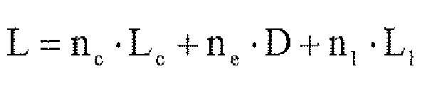
- the length L 1 of this zone depends on the optical length L of the source. This optical length depends on the medium traversed by the optical beam to the mirror and is composed of the middle of the cavity which corresponds essentially to that of the laser material, possibly a medium in free space and the medium formed by the guide of the entrance area.
- the concave mirror may be arranged directly at the entrance of the optical element, which reduces the length of the entry zone to the arrow h of the concave mirror.
- the mirror of the optical element is concave at least in a guide plane. It is advantageously produced by a local variation of effective index of the guide of the entry zone. This index variation can be obtained in particular by a cavity located in the substrate above the planar guide, by a local deposition of at least one layer on the substrate above the planar guide, by a local burial of the planar guide. , by an ion exchange located in the substrate above the planar guide or by a Bragg grating in the substrate above the planar guide.
- this list is not exhaustive and other embodiments of the concave mirror can be used to achieve the optical element of the invention.
- the concave mirror of the invention is further able to filter one or more wavelengths of the beam emitted by the laser cavity by selectively reflecting said wavelengths.
- a mirror formed by a Bragg grating will advantageously be used.
- n 1 is the effective index of the input guidance area
- n c , n e are the refractive indices respectively of the material of the laser cavity and the medium of the free space zone interposed between the cavity and the guided optical element
- L c , D, L 1 are respectively the lengths of the cavity, the free space area between the cavity and the guided optical element, and the entrance area.
- the concave mirror has, as we have seen, a radius of curvature R and is disposed at a distance from the laser cavity such that it forms with the input zone, the medium interposed between said cavity and the element guided optics and the laser cavity, an extended laser cavity, the concave mirror for transmitting a portion of the laser beam established in the extended cavity.
- the reflectivity of the concave mirror is partial (a few% to a few tens of%).
- focusing means such as, for example, collimation means are interposed between the laser cavity and the guided optical element in order to optimize the coupling between the laser cavity and the input of the element at least in a plane perpendicular to the guide plane of the input zone and perpendicular to the direction of propagation of the light beam.
- the adaptation guidance zone advantageously comprises a funnel-shaped planar guide called Typing in Anglo-Saxon terminology at least in the guiding plane of the guide.
- This adaptation zone makes it possible to concentrate the light power of the optical beam in the microguide of the exit zone.
- the adaptation guide zone is adiabatic in order to allow a slow transition between the planar guide and the microguide and thus to lose as little as possible of the light power.
- the laser source of the invention further comprises at least one divider an input and n outputs, in the output area of the element, said divider being input connected to the microguide so that the n outputs of the divider form n outputs of the source.
- the laser source according to the invention furthermore comprises x couplers (with integer x greater than or equal to 1) in the exit zone of the element, each coupler being associated with the microguide, so that the microguide and each of the couplers form an output of the source.
- the invention thus makes it possible to produce a laser source with several emitting outputs, the light beam emitted at each of these outputs being monomode or little multimode.
- the figure 1 illustrates in section a first embodiment of the source of the invention. This cut is made according to a plane yz guide.
- This source essentially comprises a laser cavity 1, able to emit an optical beam 5, and a guided optical element 3.
- the laser cavity is, for example, a monostrip laser diode that makes it possible, for example, to have a high power optical beam.
- a monostrip laser diode that makes it possible, for example, to have a high power optical beam.
- the laser cavity comprises two mirrors R 1 and R 2; preferably the mirror R 1 is very reflective, for example of the order of 80% and the mirror R 2 is non-reflective or weakly reflective, for example of the order of a few% or even less.
- This guided optical element is advantageously made in integrated optics from a monolayer or multilayer substrate 23 in which are formed the input zone, the adaptation zone and the output zone.
- the substrate is a glass substrate and the guides and microguides of this element are made by ion exchange techniques in the glass.
- the guide plane is the same for the different parts of the source, it being understood that when the guides are more or less buried, the guide plane of the different parts, or even the guide plane in each part, can be in separate planes.
- the entry zone G 1 comprises a planar guide, referenced 25.
- This guide extends over the entire length L 1 of the zone G 1 , and widens along the axis y advantageously from the inlet of the guide at its end which is associated with the concave mirror 7.
- the divergent shape of the planar guide allows the light beam 5a issuing from the laser cavity to propagate freely in the area G 1 and to obtain a stable extended laser cavity.
- planar guide may have a completely different shape as long as its dimensions along the y axis are greater than the dimensions along the same axis of the guided optical beam 5a, in G 1 .
- the optical beam has one or more modes enlarged in the plane yz.
- the concavity of the mirror is defined in the plane yz.
- the axis of symmetry of the mirror 1 in this plane corresponds to the axis z which is the direction of propagation of the light beam.
- This concave mirror makes it possible to produce an extended laser cavity. It transmits the light beam 5a from the laser cavity 1 and guided by the planar guide 25 of the input zone. This mirror is partially reflective. Its reflectivity is for example from a few% to a few tens of%.
- the mirror may also be used as a filter, for example of wavelength, so that the mirror 7 transmits to the area G 2 a light beam 5b with one or more selected wavelengths.
- This mirror is advantageously produced by a local variation of effective index of the planar guide 25.
- the adaptation guide zone G 2 which is optically connected to the planar guide 25 by the concave mirror, is intended to focus the spatially expanded optical beam in the microguide 9.
- This adaptation zone G 2 is produced by a planar guide 27 whose width along the y axis decreases from zone G 1 to zone G 3 until it has the same width as that of microguide 9 to which it is connected. optically.
- the convergence of the planar guide 27 from G 1 to microguide 9 is adiabatically performed to minimize optical losses in the guide.
- This funnel-shaped convergence of the planar guide 27 (called Typing in Anglo-Saxon terminology) is at least in the guide plane yz of the guide.
- the length of this zone G 2 is L 2 . It is determined so as to enable the light power of the light beam transmitted by the mirror to be concentrated in the microguide 9.
- the last zone G 3 has a length L 3 and comprises at least one microguide 9 which makes it possible to bring the light beam coming from the zone adapted to an output S 1 of the guided optical element.
- the output S 1 may be, as shown in this figure, on one side of the substrate. 23, perpendicular to the z axis, but it could also be on another side of this substrate.
- the medium traversed by the optical beam is thus composed of the middle of the cavity 1, which essentially corresponds to that of the laser material, the medium of the zone in free space (generally air) and the medium formed by the guide planar 25 of the entrance area.
- n c , n e are the refractive indices respectively of the material of the laser cavity and the middle of the zone of free space interposed between the cavity and the guided optical element and n 1 is the effective index of the planar guide 25, and L c , D, L 1 are respectively the lengths of the cavity 1, the free space area between the cavity and the guided optical element, and the input zone G 1 .
- the length is given by the manufacturer of the laser cavity 1 and is generally between 100 to 1000 ⁇ m.
- the length L 1 may be more or less important. In some cases, the concave mirror may even be arranged directly at the entrance of the optical element, which reduces the length of the entry zone to the arrow h of the concave mirror. This length L 1 must be such that L 1 + L 2 allow a good coupling in the microguide. L 1 + L 2 will generally be greater than 10,000 ⁇ m.
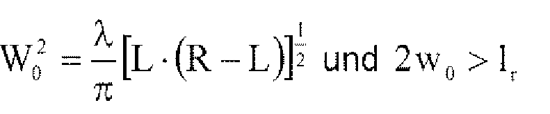
- the dimensions of the concave mirror 7, are determined so that the diameter 2.w 0 of the optical beam 5 on the plane mirror R 1 (w 0 being the radius of said beam) is greater than the width of the ribbon cavity 1.
- w 0 the diameter of the optical beam 5 on the plane mirror R 1 (w 0 being the radius of said beam) is greater than the width of the ribbon cavity 1.
- w is obtained to be greater than about 80 ⁇ m (or even 100 ⁇ m).
- the diameter d of the mirror must be greater than 2w.
- d will be greater than or equal to 200 ⁇ m.
- h 1 ⁇ m.
- the figure 2 is a variant in the xz plane of the first embodiment having, in the free space between the laser cavity 1 and the guided optical element 3, focusing means 15.
- These focusing means are made for example by collimation means, they optimize the coupling between the laser cavity and the input of the element 3, at least in the xz plane perpendicular to the guide plane.
- the beam 5 from the laser cavity is generally strongly divergent along the x axis and more weakly divergent along the y axis. It is therefore particularly advantageous to focus the beam in the xz plane.
- These focusing means are made for example by a lens of the cylindrical, spherical type, by a micro-lens or by a gradient index fiber.
- An anti-reflection treatment of the focusing means can be made to avoid forming parasitic optical cavities with the laser cavity.
- the figure 3 schematically shows in section a second embodiment of the source of the invention.
- the laser cavity is disposed directly on one of the walls parallel to the xy plane of the guided optical element at the input guiding zone G 1 .
- Such an assembly can be obtained by all the conventional assembly techniques.
- the length L then corresponds to n c .L c + n 1 .L 1 and is equal for example also to 20 000 microns.
- the figure 4 schematically shows in section a laser source according to the invention with several optical outputs.
- the zone G 3 comprises two couplers 31, 33 disposed respectively on either side of the microguide 9 so that the source comprises three outputs: the output S 1 of the microguide 9, the output S 2 of the coupler 31 and the output S 3 of the coupler 33.
- the couplers 31, 33 are made by microguides in the substrate 23.
- the output S 1 is situated on one wall of the element 3, parallel to the xy plane while the outputs S 2 and S 3 are on walls that are distinct from each other and parallel to the xz plane.
- the outputs S 1 , S 2 , S 3 can be arranged differently and in particular all be on one of the walls of the substrate.
- the figure 5 schematically represents a variant of the figure 4 in which to have three outputs S 1 , S 2 and S 3 , the area G 3 comprises a divider 35 from 1 to 3 connected to the microguide 9.
- the three outputs S 1 , S 2 , S 3 are located on the same wall parallel to the plane yx of the element.
- other configurations can be realized.
- FIG. 6a to 6e illustrate in section along a plane xz, five examples of concave mirrors used in the invention.
- this index variation is obtained by a localized etching of the substrate 23 above the planar guide 25 of the entry zone.
- This etching makes it possible to obtain a concave cavity filled by the ambient medium, in general of the air.
- This cavity has in the plane yz not shown in this figure a radius of curvature R and a diameter d as defined above.
- this cavity has a depth of some 100 nm and a width in the xz plane of a few microns.
- the mirror 7 is thus formed by this cavity 61 and the portion of the guide 25 in which the cavity induces this index variation.
- this variation of index is obtained by a local deposition of at least one layer 63 on the substrate above the planar guide 25.
- This deposit has in the yz plane (not shown) a radius of curvature R and a diameter d as defined previously.
- the deposit 63 is for example silica, a metal or a polymer of some 100 nm to some 10 microns thick and a width in the xz plane of a few microns.
- the mirror 7 is thus formed by this layer 63 and the part of the guide 25 in which the layer induces this index variation.
- this index variation is obtained by a local burial 65 of the planar guide 25 in the substrate.
- This burial 65 has in the yz plane (not shown) a radius of curvature R and a diameter d as defined above.
- This burial is obtained for example in the case of a glass substrate with a guide made by the ion exchange technique by localized diffusion through a mask, for example aluminum.
- the mirror 7 is therefore formed by the portion of the guide 25 in which the local burst induces this index variation.
- this index variation is obtained by a Bragg grating 67 in the substrate above the planar guide 25.
- This network may comprise a few periods to a few hundred periods.
- the network 67 comprises three periods comprising etchings 69 formed in the substrate.
- This network as described above has in the yz plane (not shown) a radius of curvature R and a diameter d as defined above.
- This grating is etched in the substrate, either by conventional photolithography and etching techniques, or by direct photo-inscription when the substrate is photosensitive.
- the depth of the engravings is for example from a few 10 to some 100 nm and the width in the xz plane of these etchings is for example p / 2.
- the mirror 7 is thus formed by this network 67 and the part of the guide 25 in which the network induces this index variation.
- figure 6e represents a mirror 7 obtained by an ion exchange localized in the substrate.
- the localized ion exchange is obtained by using a bath containing, for example, Ag + ions for a a glass substrate containing Na + ions and an appropriate mask so that the ion exchange is carried out in a region 70 of the substrate over a width in the plane of the figure of a few ⁇ m and with the parameters R and d as defined previously.
- the mirror 7 is thus formed by this zone 70 and the portion of the guide 25 in which said zone induces this index variation.
- the laser source of the invention makes it possible to provide single-mode or low-multimode light beams on one or more outputs and can have a high power.
- the source of the invention is applicable in many fields and in particular as a pump for optical amplifiers or for fiber or solid lasers or as a laser source for machining and / or marking materials.
Landscapes
- Physics & Mathematics (AREA)
- Condensed Matter Physics & Semiconductors (AREA)
- General Physics & Mathematics (AREA)
- Electromagnetism (AREA)
- Optics & Photonics (AREA)
- Optical Couplings Of Light Guides (AREA)
- Crystals, And After-Treatments Of Crystals (AREA)
- Lasers (AREA)
- Laser Surgery Devices (AREA)
- Radiation-Therapy Devices (AREA)
Claims (16)
- Laserquelle mit ausgedehntem Laserresonator, umfassend:- einen Laserresonator (1), der dazu ausgelegt ist, einen optischen Strahl (5) zu emittieren,- ein Lichtleiterelement (3), weiche in einem Substrat folgendes aufweiset:dadurch gekenntzeichnet, dass die Eingangsleiterzone einen Spiegel umfasst, der wenigstens in einer Leiterebene der Eingangszone konkav ist, derart, dass mit dem Laserresonator ein ausgedehnter Laserresonator realisiert wird.• eine Eingangsleiterzone (G1),• eine Ausgangszone (G3), die wenigstens einen Mikroleiter (9) umfasst, der wenigstens einem optischen Ausgang (S1) der Quelle zugeordnet ist, und• eine planare Anpassungsleiterzone (G2) zwischen der Eingangszone und dem Mikroleiter, wobei die Eingangsleiterzone dazu ausgelegt ist, den vom Resonator emittierten optischen Strahl zu empfangen und ihn zur Anpassungsleiterzone zu transmittierten, die dazu ausgelegt ist, ihn zum Mikroleiter hin zu leiten,
- Laserquelle nach Anspruch 1, dadurch gekenntzeichnet, dass der Laserresonator eine Laserdiode ist, die wenigstens einen Planspiegel (R1) umfasst.
- Laserquelle nach Anspruch 1, dadurch gekennzeichnet, dass der Laserresonator (1) direkt auf dem Lichtleiterelement (3) im Bereich der Eingangsleiterzone (G1) dieses Elements angeordnet ist.
- Laserquelle nach Anspruch 1, dadurch gekenntzeichnet, dass der Laserresonator (1) von der Eingangszone des Lichtleiterelements (3) durch eine Freiraumzone getrennt ist.
- Laserquelle nach Anspruch 4, dadurch gekennzeichnet, dass die Quelle ferner Fokussiermittel umfasst, die zwischen dem Resonator (1) und der Eingangszone des Lichtleiterelements (3) angeordnet sind, wobei diese Mittel dazu ausgelegt sind, den vom Laserresonator emittierten optischen Strahl in die Eingangsleiterzone wenigstens in einer Ebene zu fokussieren, die orthogonal ist zur Leiterebene der Zone.
- Laserquelle nach Anspruch 1, dadurch gekennzeichnet, dass das Lichtleiterelement (3) ausgehend von einem Glassubstrat hergestellt ist.
- Laserquelle nach Anspruch 1, dadurch gekennzeichnet, dass die Eingangsleiterzone einen planaren Leiter (25) umfasst, der mittels des konkaven Spiegels (7) mit der Anpassungsleiterzone (G2) verbunden ist.
- Laserquelle nach Anspruch 7, dadurch gekennzeichnet, dass der konkave Spiegel (7) durch eine lokale Variation des effektiven Index des planaren Leiters der Eingangsleiterzone realisiert ist.
- Laserquelle nach Anspruch 8, dadurch gekennzeichnet, dass die Variation des effektiven Index durch einen Hohlraum in dem Substrat über dem planaren Leiter realisiert ist, oder durch eine lokale Abscheidung wenigstens einer Schicht auf dem Substrat über dem planaren Leiter oder durch ein lokales Eingraben des planaren Leiters, oder durch einen Iokalisierten Ionenaustausch in dem Substrat über dem planaren Leiter, oder auch durch ein Bragg-Gitter in dem Substrat über dem planaren Leiter.
- Laserquelle nach Anspruch 1, dadurch gekennzeichnet, dass der konkave Spiegel dazu ausgelegt ist, den optischen Strahl nach Wellenlängen zu filtern
- Laserquelle nach Anspruch 1, dadurch gekennzeichnet, dass die Anpassungsleiterzone einen trichterförmigen planaren Leiter (27) umfasst.
- Laserquelle nach Anspruch 19 , dadurch gekennzeichnet, dass der trichterförmige planare Leiter der Anpassungsleiterzone adiabatisch ist.
- Laserquelle nach Anspruch 1, dadurch gekennzeichnet, dass sie ferner wenigstens einen Teiler (35) mit einem Eingang und mit n Ausgängen in der Ausgangszone (G3) des Elementes umfasst, wobei der Teiler am Eingang mit dem Mikroleiter (9) derart verbunden ist, dass die n Ausgänge des Teilers n Ausgänge der Quelle bilden.
- Laserquelle nach Anspruch 1, dadurch gekennzeichnet, dass sie ferner x Koppler in der Ausgangszone (G3) des Elements umfasst, wobei jeder Koppler (31, 33) dem Mikraleiter derart zugeordnet ist, dass jeweils der Mikroleiter und jeder der Koppler einen Ausgang (S1, S2, S3) der Quelle bilden,
- Laserquelle nach Anspruch 1, dadurch gekennzeichnet, dass der konkave Spiegel einen Krümmungsradius R aufweist, der größer oder gleich einer optischen Länge der Quelle ist, definiert durch L=nc·Lc+ne·D+nl·Ll, wobei n1 der effektive Index der Eingangsleiterzone ist und wobei nc, ne die Brechungsindices des Materials des Laserresonators bzw. der Umgebung der Freiraumzone sind, die sich zwischen dem Resonator und dem Lichtleiterelement befindet, und wobei Lc,D,L1 die Längen des Resonators, der zwischen dem Resonator und dem Lichtleiterelement befindlichen Freiraumzone beziehungsweise der Eingangszone sind.
- Laserquelle nach Anspruch 15, dadurch gekennzeichnet, dass die geometrischen Eigenschaften des konkaven Spiegels (7) im Fall der Verwendung eines Band-Laserresonators durch die folgenden Gleichungen und Ungleichungen definiert sind:-
 -
- -
- -
- -
- -wobei λ die betrachtete Wellenlänge des Lichtstrahls ist, w0 der Radius des Strahls auf einem Planspiegel des Resonators ist, lr die Breite des Bandes des Laserresonators ist, R der Krümmungsradius des konkaven Spiegels ist, L die optische Länge der Quelle ist, w der Radius des Lichtsstrahls auf dem konkaven Spiegel ist, h die Durchbiegung des konkaven Spiegels in der Leiterebene ist und d der Durchmesser dieses Spiegels ist.
Applications Claiming Priority (3)
| Application Number | Priority Date | Filing Date | Title |
|---|---|---|---|
| FR0111043A FR2828960B1 (fr) | 2001-08-23 | 2001-08-23 | Source laser en optique guidee |
| FR0111043 | 2001-08-23 | ||
| PCT/FR2002/002915 WO2003019737A2 (fr) | 2001-08-23 | 2002-08-21 | Source laser en optique guidee |
Publications (2)
| Publication Number | Publication Date |
|---|---|
| EP1433232A2 EP1433232A2 (de) | 2004-06-30 |
| EP1433232B1 true EP1433232B1 (de) | 2010-01-06 |
Family
ID=8866682
Family Applications (1)
| Application Number | Title | Priority Date | Filing Date |
|---|---|---|---|
| EP02772510A Expired - Lifetime EP1433232B1 (de) | 2001-08-23 | 2002-08-21 | Wellenleiterlaserquelle |
Country Status (8)
| Country | Link |
|---|---|
| US (1) | US20050063439A1 (de) |
| EP (1) | EP1433232B1 (de) |
| AT (1) | ATE454736T1 (de) |
| AU (1) | AU2002337275A1 (de) |
| CA (1) | CA2457771A1 (de) |
| DE (1) | DE60235022D1 (de) |
| FR (1) | FR2828960B1 (de) |
| WO (1) | WO2003019737A2 (de) |
Families Citing this family (1)
| Publication number | Priority date | Publication date | Assignee | Title |
|---|---|---|---|---|
| CN109193342B (zh) * | 2018-10-15 | 2019-11-15 | 中国科学院理化技术研究所 | 一种半导体激光器 |
Family Cites Families (14)
| Publication number | Priority date | Publication date | Assignee | Title |
|---|---|---|---|---|
| NL268679A (de) * | 1960-10-07 | |||
| JPS60110187A (ja) * | 1983-11-18 | 1985-06-15 | Matsushita Electric Ind Co Ltd | 光帰還型半導体レ−ザ装置 |
| US4553244A (en) * | 1984-04-25 | 1985-11-12 | Gte Communications Products Corporation | Laser beam energy profile synthesizer |
| US4710940A (en) * | 1985-10-01 | 1987-12-01 | California Institute Of Technology | Method and apparatus for efficient operation of optically pumped laser |
| US4763975A (en) * | 1987-04-28 | 1988-08-16 | Spectra Diode Laboratories, Inc. | Optical system with bright light output |
| JPH01231387A (ja) * | 1988-03-11 | 1989-09-14 | Fujitsu Ltd | 半導体発光素子 |
| US5046184A (en) * | 1990-04-05 | 1991-09-03 | University Of California | Method and apparatus for passive mode locking high power lasers |
| US5436920A (en) * | 1993-05-18 | 1995-07-25 | Matsushita Electric Industrial Co., Ltd. | Laser device |
| US5513196A (en) * | 1995-02-14 | 1996-04-30 | Deacon Research | Optical source with mode reshaping |
| US6778582B1 (en) * | 2000-03-06 | 2004-08-17 | Novalux, Inc. | Coupled cavity high power semiconductor laser |
| US20060029120A1 (en) * | 2000-03-06 | 2006-02-09 | Novalux Inc. | Coupled cavity high power semiconductor laser |
| FR2821166B1 (fr) * | 2001-02-19 | 2004-06-18 | Teem Photonics | Composant de couplage realise en optique integree, apte a adapter une source lumineuse a un element d'optique guidee et laser de puissance le comportant |
| US6944192B2 (en) * | 2001-03-14 | 2005-09-13 | Corning Incorporated | Planar laser |
| KR101015499B1 (ko) * | 2004-06-19 | 2011-02-16 | 삼성전자주식회사 | 복수의 파장을 발생시키는 반도체 레이저 소자 및 상기반도체 레이저 소자용 레이저 펌핑부 |
-
2001
- 2001-08-23 FR FR0111043A patent/FR2828960B1/fr not_active Expired - Fee Related
-
2002
- 2002-08-21 AT AT02772510T patent/ATE454736T1/de not_active IP Right Cessation
- 2002-08-21 DE DE60235022T patent/DE60235022D1/de not_active Expired - Lifetime
- 2002-08-21 US US10/487,249 patent/US20050063439A1/en not_active Abandoned
- 2002-08-21 EP EP02772510A patent/EP1433232B1/de not_active Expired - Lifetime
- 2002-08-21 CA CA002457771A patent/CA2457771A1/fr not_active Abandoned
- 2002-08-21 WO PCT/FR2002/002915 patent/WO2003019737A2/fr not_active Ceased
- 2002-08-21 AU AU2002337275A patent/AU2002337275A1/en not_active Abandoned
Also Published As
| Publication number | Publication date |
|---|---|
| FR2828960A1 (fr) | 2003-02-28 |
| EP1433232A2 (de) | 2004-06-30 |
| WO2003019737A3 (fr) | 2003-11-06 |
| CA2457771A1 (fr) | 2003-03-06 |
| ATE454736T1 (de) | 2010-01-15 |
| WO2003019737A2 (fr) | 2003-03-06 |
| AU2002337275A1 (en) | 2003-03-10 |
| DE60235022D1 (de) | 2010-02-25 |
| FR2828960B1 (fr) | 2004-03-12 |
| US20050063439A1 (en) | 2005-03-24 |
Similar Documents
| Publication | Publication Date | Title |
|---|---|---|
| EP3610309B1 (de) | Photonischer chip mit integrierter kollimationsstruktur | |
| EP3540878B1 (de) | Photonenvorrichtung, die einen laser umfasst, der optisch mit einem silizium-wellenleiter verbunden ist, und herstellungsverfahren einer solchen photonenvorrichtung | |
| EP0637764B1 (de) | Herstellung einer optischen Kopplungsstruktur, die einen abgespaltenen optischen Wellenleiter und eine Halterung für optische Fasern integriert | |
| EP0451047B1 (de) | Vor Umwelteinflüssen geschützte integrierte optische Komponente und Verfahren zu ihrer Herstellung | |
| US5995692A (en) | Light emitting device module | |
| EP3521879A1 (de) | Photonischer chip mit integrierter kollimationsstruktur | |
| JP2007534155A (ja) | レンズ付き表面放射入射光子デバイス | |
| EP0776075B1 (de) | Laservorrichtung, insbesondere zum optischen Pumpen | |
| US6430207B1 (en) | High-power laser with transverse mode filter | |
| EP1390786B1 (de) | Integrierter optischer bauteil zur kopplung | |
| US7106773B1 (en) | Large modal volume semiconductor laser system with spatial mode filter | |
| EP1433232B1 (de) | Wellenleiterlaserquelle | |
| JP2001185805A (ja) | 光半導体装置 | |
| EP0977327A1 (de) | Freiraumlaser mit selbstjustierter Auskoppelfaser | |
| JP4086260B2 (ja) | 発光素子モジュール | |
| EP1234360B1 (de) | Verfahren und vorrichtung zur wellenlängenumschaltung einer laserquelle | |
| EP1745531B1 (de) | Strahlungsemitter mit geneigtem pumpstrahl | |
| EP4034923B1 (de) | Optisches system und verfahren zu dessen herstellung | |
| EP1030412B1 (de) | Optischer Verstärker | |
| FR2777710A1 (fr) | Dispositif de laser a semi-conducteur capable de reduire la perte de couplage par rapport a une fibre optique | |
| EP1397850A1 (de) | Aktives optisches kopplungselement | |
| WO2002075386A2 (fr) | Structure guidante permettant de transformer un mode de propagation de profil de type gaussien en un mode de propagation de profil elargi | |
| Khalili et al. | Side-coupled in-line fiber-semiconductor laser |
Legal Events
| Date | Code | Title | Description |
|---|---|---|---|
| PUAI | Public reference made under article 153(3) epc to a published international application that has entered the european phase |
Free format text: ORIGINAL CODE: 0009012 |
|
| 17P | Request for examination filed |
Effective date: 20040129 |
|
| AK | Designated contracting states |
Kind code of ref document: A2 Designated state(s): AT BE BG CH CY CZ DE DK EE ES FI FR GB GR IE IT LI LU MC NL PT SE SK TR |
|
| AX | Request for extension of the european patent |
Extension state: AL LT LV MK RO SI |
|
| 17Q | First examination report despatched |
Effective date: 20060629 |
|
| GRAP | Despatch of communication of intention to grant a patent |
Free format text: ORIGINAL CODE: EPIDOSNIGR1 |
|
| GRAS | Grant fee paid |
Free format text: ORIGINAL CODE: EPIDOSNIGR3 |
|
| GRAA | (expected) grant |
Free format text: ORIGINAL CODE: 0009210 |
|
| AK | Designated contracting states |
Kind code of ref document: B1 Designated state(s): AT BE BG CH CY CZ DE DK EE ES FI FR GB GR IE IT LI LU MC NL PT SE SK TR |
|
| REG | Reference to a national code |
Ref country code: GB Ref legal event code: FG4D Free format text: NOT ENGLISH |
|
| REG | Reference to a national code |
Ref country code: CH Ref legal event code: EP |
|
| REG | Reference to a national code |
Ref country code: IE Ref legal event code: FG4D |
|
| REF | Corresponds to: |
Ref document number: 60235022 Country of ref document: DE Date of ref document: 20100225 Kind code of ref document: P |
|
| REG | Reference to a national code |
Ref country code: NL Ref legal event code: VDEP Effective date: 20100106 |
|
| PG25 | Lapsed in a contracting state [announced via postgrant information from national office to epo] |
Ref country code: AT Free format text: LAPSE BECAUSE OF FAILURE TO SUBMIT A TRANSLATION OF THE DESCRIPTION OR TO PAY THE FEE WITHIN THE PRESCRIBED TIME-LIMIT Effective date: 20100106 |
|
| PG25 | Lapsed in a contracting state [announced via postgrant information from national office to epo] |
Ref country code: ES Free format text: LAPSE BECAUSE OF FAILURE TO SUBMIT A TRANSLATION OF THE DESCRIPTION OR TO PAY THE FEE WITHIN THE PRESCRIBED TIME-LIMIT Effective date: 20100417 Ref country code: NL Free format text: LAPSE BECAUSE OF FAILURE TO SUBMIT A TRANSLATION OF THE DESCRIPTION OR TO PAY THE FEE WITHIN THE PRESCRIBED TIME-LIMIT Effective date: 20100106 Ref country code: PT Free format text: LAPSE BECAUSE OF FAILURE TO SUBMIT A TRANSLATION OF THE DESCRIPTION OR TO PAY THE FEE WITHIN THE PRESCRIBED TIME-LIMIT Effective date: 20100506 |
|
| REG | Reference to a national code |
Ref country code: IE Ref legal event code: FD4D |
|
| PG25 | Lapsed in a contracting state [announced via postgrant information from national office to epo] |
Ref country code: FI Free format text: LAPSE BECAUSE OF FAILURE TO SUBMIT A TRANSLATION OF THE DESCRIPTION OR TO PAY THE FEE WITHIN THE PRESCRIBED TIME-LIMIT Effective date: 20100106 |
|
| PG25 | Lapsed in a contracting state [announced via postgrant information from national office to epo] |
Ref country code: EE Free format text: LAPSE BECAUSE OF FAILURE TO SUBMIT A TRANSLATION OF THE DESCRIPTION OR TO PAY THE FEE WITHIN THE PRESCRIBED TIME-LIMIT Effective date: 20100106 Ref country code: CY Free format text: LAPSE BECAUSE OF FAILURE TO SUBMIT A TRANSLATION OF THE DESCRIPTION OR TO PAY THE FEE WITHIN THE PRESCRIBED TIME-LIMIT Effective date: 20100106 Ref country code: GR Free format text: LAPSE BECAUSE OF FAILURE TO SUBMIT A TRANSLATION OF THE DESCRIPTION OR TO PAY THE FEE WITHIN THE PRESCRIBED TIME-LIMIT Effective date: 20100407 Ref country code: SE Free format text: LAPSE BECAUSE OF FAILURE TO SUBMIT A TRANSLATION OF THE DESCRIPTION OR TO PAY THE FEE WITHIN THE PRESCRIBED TIME-LIMIT Effective date: 20100106 Ref country code: IE Free format text: LAPSE BECAUSE OF FAILURE TO SUBMIT A TRANSLATION OF THE DESCRIPTION OR TO PAY THE FEE WITHIN THE PRESCRIBED TIME-LIMIT Effective date: 20100106 |
|
| PLBE | No opposition filed within time limit |
Free format text: ORIGINAL CODE: 0009261 |
|
| STAA | Information on the status of an ep patent application or granted ep patent |
Free format text: STATUS: NO OPPOSITION FILED WITHIN TIME LIMIT |
|
| PG25 | Lapsed in a contracting state [announced via postgrant information from national office to epo] |
Ref country code: BG Free format text: LAPSE BECAUSE OF FAILURE TO SUBMIT A TRANSLATION OF THE DESCRIPTION OR TO PAY THE FEE WITHIN THE PRESCRIBED TIME-LIMIT Effective date: 20100406 Ref country code: CZ Free format text: LAPSE BECAUSE OF FAILURE TO SUBMIT A TRANSLATION OF THE DESCRIPTION OR TO PAY THE FEE WITHIN THE PRESCRIBED TIME-LIMIT Effective date: 20100106 Ref country code: SK Free format text: LAPSE BECAUSE OF FAILURE TO SUBMIT A TRANSLATION OF THE DESCRIPTION OR TO PAY THE FEE WITHIN THE PRESCRIBED TIME-LIMIT Effective date: 20100106 |
|
| 26N | No opposition filed |
Effective date: 20101007 |
|
| PG25 | Lapsed in a contracting state [announced via postgrant information from national office to epo] |
Ref country code: DK Free format text: LAPSE BECAUSE OF FAILURE TO SUBMIT A TRANSLATION OF THE DESCRIPTION OR TO PAY THE FEE WITHIN THE PRESCRIBED TIME-LIMIT Effective date: 20100106 |
|
| BERE | Be: lapsed |
Owner name: TEEM PHOTONICS Effective date: 20100831 |
|
| PG25 | Lapsed in a contracting state [announced via postgrant information from national office to epo] |
Ref country code: MC Free format text: LAPSE BECAUSE OF NON-PAYMENT OF DUE FEES Effective date: 20100831 Ref country code: IT Free format text: LAPSE BECAUSE OF FAILURE TO SUBMIT A TRANSLATION OF THE DESCRIPTION OR TO PAY THE FEE WITHIN THE PRESCRIBED TIME-LIMIT Effective date: 20100106 |
|
| REG | Reference to a national code |
Ref country code: CH Ref legal event code: PL |
|
| PG25 | Lapsed in a contracting state [announced via postgrant information from national office to epo] |
Ref country code: LI Free format text: LAPSE BECAUSE OF NON-PAYMENT OF DUE FEES Effective date: 20100831 Ref country code: CH Free format text: LAPSE BECAUSE OF NON-PAYMENT OF DUE FEES Effective date: 20100831 |
|
| PG25 | Lapsed in a contracting state [announced via postgrant information from national office to epo] |
Ref country code: BE Free format text: LAPSE BECAUSE OF NON-PAYMENT OF DUE FEES Effective date: 20100831 |
|
| PG25 | Lapsed in a contracting state [announced via postgrant information from national office to epo] |
Ref country code: LU Free format text: LAPSE BECAUSE OF NON-PAYMENT OF DUE FEES Effective date: 20100821 |
|
| PG25 | Lapsed in a contracting state [announced via postgrant information from national office to epo] |
Ref country code: TR Free format text: LAPSE BECAUSE OF FAILURE TO SUBMIT A TRANSLATION OF THE DESCRIPTION OR TO PAY THE FEE WITHIN THE PRESCRIBED TIME-LIMIT Effective date: 20100106 |
|
| REG | Reference to a national code |
Ref country code: FR Ref legal event code: PLFP Year of fee payment: 15 |
|
| REG | Reference to a national code |
Ref country code: FR Ref legal event code: PLFP Year of fee payment: 16 |
|
| PGFP | Annual fee paid to national office [announced via postgrant information from national office to epo] |
Ref country code: GB Payment date: 20171228 Year of fee payment: 16 |
|
| REG | Reference to a national code |
Ref country code: FR Ref legal event code: PLFP Year of fee payment: 17 |
|
| GBPC | Gb: european patent ceased through non-payment of renewal fee |
Effective date: 20180821 |
|
| PG25 | Lapsed in a contracting state [announced via postgrant information from national office to epo] |
Ref country code: GB Free format text: LAPSE BECAUSE OF NON-PAYMENT OF DUE FEES Effective date: 20180821 |
|
| PGFP | Annual fee paid to national office [announced via postgrant information from national office to epo] |
Ref country code: FR Payment date: 20201228 Year of fee payment: 19 |
|
| PGFP | Annual fee paid to national office [announced via postgrant information from national office to epo] |
Ref country code: DE Payment date: 20210112 Year of fee payment: 19 |
|
| REG | Reference to a national code |
Ref country code: DE Ref legal event code: R119 Ref document number: 60235022 Country of ref document: DE |
|
| PG25 | Lapsed in a contracting state [announced via postgrant information from national office to epo] |
Ref country code: FR Free format text: LAPSE BECAUSE OF NON-PAYMENT OF DUE FEES Effective date: 20210831 Ref country code: DE Free format text: LAPSE BECAUSE OF NON-PAYMENT OF DUE FEES Effective date: 20220301 |