EP1433005B1 - Verfahren und anordnung zur herstellung von faseroptischen baugruppen - Google Patents
Verfahren und anordnung zur herstellung von faseroptischen baugruppen Download PDFInfo
- Publication number
- EP1433005B1 EP1433005B1 EP02773097A EP02773097A EP1433005B1 EP 1433005 B1 EP1433005 B1 EP 1433005B1 EP 02773097 A EP02773097 A EP 02773097A EP 02773097 A EP02773097 A EP 02773097A EP 1433005 B1 EP1433005 B1 EP 1433005B1
- Authority
- EP
- European Patent Office
- Prior art keywords
- pallet
- optical fiber
- track
- processing
- robot device
- Prior art date
- Legal status (The legal status is an assumption and is not a legal conclusion. Google has not performed a legal analysis and makes no representation as to the accuracy of the status listed.)
- Expired - Lifetime
Links
- 230000000712 assembly Effects 0.000 title claims abstract description 29
- 238000000429 assembly Methods 0.000 title claims abstract description 29
- 239000013307 optical fiber Substances 0.000 title claims abstract description 29
- 238000000034 method Methods 0.000 title claims abstract description 17
- 238000004519 manufacturing process Methods 0.000 title claims description 25
- 239000000835 fiber Substances 0.000 claims abstract description 61
- 238000012545 processing Methods 0.000 claims abstract description 61
- 230000005693 optoelectronics Effects 0.000 claims abstract description 8
- 238000012546 transfer Methods 0.000 claims description 24
- 230000001360 synchronised effect Effects 0.000 claims description 2
- 238000005253 cladding Methods 0.000 description 3
- 239000011248 coating agent Substances 0.000 description 3
- 238000000576 coating method Methods 0.000 description 3
- 238000004891 communication Methods 0.000 description 3
- 230000003287 optical effect Effects 0.000 description 3
- 238000005452 bending Methods 0.000 description 2
- 238000004140 cleaning Methods 0.000 description 2
- 238000003860 storage Methods 0.000 description 2
- NIXOWILDQLNWCW-UHFFFAOYSA-M Acrylate Chemical compound [O-]C(=O)C=C NIXOWILDQLNWCW-UHFFFAOYSA-M 0.000 description 1
- 238000013459 approach Methods 0.000 description 1
- 238000010276 construction Methods 0.000 description 1
- 238000012937 correction Methods 0.000 description 1
- 238000005520 cutting process Methods 0.000 description 1
- 239000003365 glass fiber Substances 0.000 description 1
- 238000011031 large-scale manufacturing process Methods 0.000 description 1
- 238000002360 preparation method Methods 0.000 description 1
- 238000012360 testing method Methods 0.000 description 1
Images


Classifications
-
- G—PHYSICS
- G02—OPTICS
- G02B—OPTICAL ELEMENTS, SYSTEMS OR APPARATUS
- G02B6/00—Light guides; Structural details of arrangements comprising light guides and other optical elements, e.g. couplings
- G02B6/24—Coupling light guides
- G02B6/255—Splicing of light guides, e.g. by fusion or bonding
- G02B6/2551—Splicing of light guides, e.g. by fusion or bonding using thermal methods, e.g. fusion welding by arc discharge, laser beam, plasma torch
-
- G—PHYSICS
- G02—OPTICS
- G02B—OPTICAL ELEMENTS, SYSTEMS OR APPARATUS
- G02B6/00—Light guides; Structural details of arrangements comprising light guides and other optical elements, e.g. couplings
- G02B6/24—Coupling light guides
-
- G—PHYSICS
- G02—OPTICS
- G02B—OPTICAL ELEMENTS, SYSTEMS OR APPARATUS
- G02B6/00—Light guides; Structural details of arrangements comprising light guides and other optical elements, e.g. couplings
- G02B6/24—Coupling light guides
- G02B6/245—Removing protective coverings of light guides before coupling
-
- G—PHYSICS
- G02—OPTICS
- G02B—OPTICAL ELEMENTS, SYSTEMS OR APPARATUS
- G02B6/00—Light guides; Structural details of arrangements comprising light guides and other optical elements, e.g. couplings
- G02B6/24—Coupling light guides
- G02B6/25—Preparing the ends of light guides for coupling, e.g. cutting
-
- G—PHYSICS
- G02—OPTICS
- G02B—OPTICAL ELEMENTS, SYSTEMS OR APPARATUS
- G02B6/00—Light guides; Structural details of arrangements comprising light guides and other optical elements, e.g. couplings
- G02B6/24—Coupling light guides
- G02B6/36—Mechanical coupling means
- G02B6/3608—Fibre wiring boards, i.e. where fibres are embedded or attached in a pattern on or to a substrate, e.g. flexible sheets
- G02B6/3612—Wiring methods or machines
-
- G—PHYSICS
- G02—OPTICS
- G02B—OPTICAL ELEMENTS, SYSTEMS OR APPARATUS
- G02B6/00—Light guides; Structural details of arrangements comprising light guides and other optical elements, e.g. couplings
- G02B6/24—Coupling light guides
- G02B6/36—Mechanical coupling means
- G02B6/3616—Holders, macro size fixtures for mechanically holding or positioning fibres, e.g. on an optical bench
-
- G—PHYSICS
- G02—OPTICS
- G02B—OPTICAL ELEMENTS, SYSTEMS OR APPARATUS
- G02B6/00—Light guides; Structural details of arrangements comprising light guides and other optical elements, e.g. couplings
- G02B6/24—Coupling light guides
- G02B6/42—Coupling light guides with opto-electronic elements
- G02B6/4201—Packages, e.g. shape, construction, internal or external details
- G02B6/4219—Mechanical fixtures for holding or positioning the elements relative to each other in the couplings; Alignment methods for the elements, e.g. measuring or observing methods especially used therefor
- G02B6/422—Active alignment, i.e. moving the elements in response to the detected degree of coupling or position of the elements
- G02B6/4226—Positioning means for moving the elements into alignment, e.g. alignment screws, deformation of the mount
Definitions
- This invention relates to a method and an arrangement for manufacturing optical fiber assemblies in which the assemblies or assembly parts like fiber lengths, opto-and optoelectronic components are transferred between processing modules.
- the continuos increase of the use of optical fibers in the area of tele- and data communication has created a demand for more efficient production of many products related to communications by fiber.
- One important such a product is various kinds of assemblies including fiber lengths.
- Typical assembly products are, optical amplifiers and optical couplers but also laser modules, receiver modules and integrated transmitter modules.
- the number of these and other opto- and optoelectronic assemblies that comprise one or more fiber lengths is increasing but still there is not known any solution for large scale production.
- a common way of manufacturing fiber optic assemblies is to bring the fiber lengths by hand to the different preparation tools needed for providing appropriate connections to components or with another fiber length. Another approach is to bring at least most of the tools one by one to the operator. Examples of such tools are: cutters for cutting the fiber, strippers for removing parts of the cladding, splicers for connecting two fiber ends and recoaters for recoating of a spliced fiber.
- An optical communication fiber normally consists of a glass fiber core of about 125 microns and a coated cladding thereon giving a total fiber diameter of about 250 microns.
- the cladding or coating is made of two layers of acrylate one inner and softer layer and one outer and harder layer. The coating is necessary for protecting the fiber core and for providing tensile and bending strength to the fiber.
- the optical fibers are still quite delicate products and the same applies to many opto- and optoelectronic components.
- a problem with today's mainly manual handling of fiber lengths and components is that they often get damages and have to be sorted out. Another problem is that the production is limited as to capacity and the quality is very much dependant on the operator's skill.
- US 6 122 936 discloses a method and an arrangment where the fibre lengths are processed automatically.
- the arrangement includes pallets onto wich the fibre lengths to be processed are fixed and subsequently transported to several processing stations like fibre stripping station, fibre cleaning station, or fibre clearing station.
- a robot device picks up the fibre on its pallet and places it together with the pallet into the respective station for processing.
- the main object of the present invention is to provide a method and an arrangement that enable a high degree of automation when manufacturing optical fiber assemblies. Another object is to provide a method and an apparatus that is adapted for smooth and gentle handling of all parts included in the assemblies during the manufacture and still another object is to achieve a method and an apparatus that provide a higher and more even quality of the fiber assemblies.
- An advantage of the present invention is that it enables gentle and careful handling of fiber lengths and components during the whole process of manufacturing optical fiber assemblies. Another advantage is that the manufacturing schedule or setup is easy to change by changing processing modules or the processing order between the modules. A further advantage is the possibility to have a fully automatic production and means for running correction of the same without any interruptions. Yet another advantage is that most kinds of processing including splicing can be carried out by one and the same production line. Still another advantage is that a number of pallet means can be processed at the same time, at different processing modules, under transportation on the tracks and in storage or circulation.
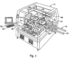
- a fiber processing cell 11 comprising an inlet 12 and an outlet 13 for pallet means 14 that are arranged for distributing optical fiber assemblies 15 to and from the cell.
- the pallet means 14 are guided on a track 16 within and outside the cell 11, said track being a transfer track 17 in the cell and a conveyor means 18 on the outside.
- the pallets means is preferable a metallic plate 19 with an upper planar surface 20 having attaching means 21 for holding assembly parts 22 in a fixed position on the surface.
- Typical assembly parts are lengths 23, 24 of optical fiber, and different opto- and optoelectronic components.
- the attaching means include separate holders 27 e.g.
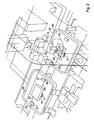
- FIG. 3 there is shown a typical layout of assembly parts 22 on the pallet.
- the optical fiber assembly under construction is symbolized by the dotted line 28.
- Two components 29, 30 and a connector 31 are so far installed and joint together by optical fiber lengths.
- a third component 32 is to be joint with the others in the next processing step and for that reason a free fiber end 33 from the second component 30 is fixed in a first clip 34 and another free end 35 from the third component 32 is fixed in a second clip 36.
- the third component is also connected with a further length 37 of fiber that for the moment is attached to the pallet awaiting a further mounting step in which the length will be spliced to a fiber of a further component.
- the transfer track 17 comprises a suitable transfer means 38, e.g. an Archimedian screw device for transferring a carriage means 39 (Fig. 4) for the pallets 14 along the track.
- the conveyor means 18 comprises e.g. endless belts or roller ways.
- a robot device 40 is arranged above the transfer track 17 and includes two gripping means 41, 42 mounted on a robot arm 43, which is movable along a first girder 44 in the upper part of the cell. Said first girder is in turn movable along second girders 45 directed transversely to the first girder.
- the shown robot device is a Cartesian robot of a kind known per see but also other robot devices may be applicable.
- the gripping means are adapted to lift and bring the free fiber ends 25, 26 to different processing modules 46 located at one side of the transfer track 17.
- the cell holds five processing modules, a module 47 for straightening the fiber and stripping the coating from the core, a module 48 for cleaning the fiber by ultrasonics, a module 49 for cleaving the fiber, a module 50 for splicing two fiber ends and a module 51 for recoating of spliced fiber ends.
- the movements of the gripping means are preset and controlled by a computer means 52 including a control unit 53 for the transfer means 38.
- the movements of the robot arm with its gripping means and the transfer of the pallet means are synchronized in such a way that all movements of the gripping means along the transfer track starts a corresponding transfer of the carriage means 39 carrying the pallet means.
- each processing cell 11 will have a carriage 39 that is movable along the transfer track 17 and is driven by the transfer means 38.
- the robot device is programmed to possess a number of processing steps in the cell and the control unit 53 is programmed to register all movements of the robot arm in the direction along the track and direct the transfer means 38 to transfer the carriage 39 with the pallet means a corresponding distance.
- the total processing in the cell often means that the robot arm has to go back and forth along the track several times before the assembly is ready to leave the cell. It is also an evident advantage in terms of capacity if more than one pallet can be processed at the same time in the cell.
- a changing mechanism is arranged for changing the order of the pallets and let one pallet pass another.
- Said mechanism comprises in the embodiment according to Fig.4 three lifting devices 54, 55, 56 located at three different stop stations along the track 17.
- Each lifting device comprises a suitable lifting system 57 e.g. a lifting cylinder and a frame 58 with four upright arms 59 that are adapted to come into lifting engagement with the pallet when the lifting frame is moved from its lower position, shown by device 54, to its upper position, shown by devices 55, 56.
- a free space is created between the pallet and the track allowing the carriage means 39 with a second pallet 14b to pass under the first pallet 14a.
- some processing steps may continue e.g. splicing and testing while the assembly on the second pallet may be subjected to another treatment in another processing module.
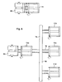
- the processing modules can be grouped together in many ways, and in Fig. 5 a structure can be seen that includes a manual in- and output cell 60 and a processing cell 11 with at least two processing modules. In Fig. 6 the structure is more complicated and includes one manual in- and output cell 60 and four processing cells 11a, 11b, 11c and 11d.
- the cells are connected by conveyor means 18 into a network that also could include not shown pallet storage and/or pallet changing means.
- the manufacture of an optical fiber assembly starts with that the operator at the in- and output cell 60 puts a first component e.g. 31 and a second component e.g. 29 each one with extending fiber lengths on the pallet means 14.
- the components are secured in a fixed position on the pallet surface by the attaching means 21 e.g. some adhesion product and the two fiber ends from the two components that are to be connected are placed in the clips 27.
- the pallet is then transferred to the conveyor means 18, which moves the pallet to the inlet 12 of the processing cell 11. In this position the pallet is changed over to the carriage means 39 included in the transfer means 38 e.g. by means of a lifting device 61 as shown in Fig. 1.
- the transfer means moves the pallet to the first processing module, which in this case is the straightening and stripping module 47 and the robot device 40 is activated to grip the fiber ends 25, 26 and move them one by one to the module.
- the robot arm moves the fiber ends to the next processing module e.g. 48 and the control means 53 is arranged to simultaneously move the carriage means 39 with the pallet means in order to avoid any unnecessary stretching or bending of the fiber lengths.
- the pallet is returned to the in-and output cell 60 on the same track 16 and an additional component with fiber lengths is placed on the pallet.
- the new two fiber ends that are to be spliced are put in the clips 27 and the transfer and processing procedure is performed in the same way again. Further components are added, mostly one by one, and the assembly is built up to its final structure while the pallet means move like a shuttle between the in- and output cell 60 and the processing cell 11.
- a layout according to Fig. 6 is advantageous and a further step could be to introduce robot devices in the in-and output cell in order to achieve a fully automated production line.
Landscapes
- Physics & Mathematics (AREA)
- General Physics & Mathematics (AREA)
- Optics & Photonics (AREA)
- Engineering & Computer Science (AREA)
- Plasma & Fusion (AREA)
- Mechanical Coupling Of Light Guides (AREA)
- Light Guides In General And Applications Therefor (AREA)
- Optical Couplings Of Light Guides (AREA)
- Multi-Process Working Machines And Systems (AREA)
- Glass Compositions (AREA)
- Inorganic Fibers (AREA)
- Automatic Assembly (AREA)
- Manufacture, Treatment Of Glass Fibers (AREA)
Claims (10)
- Verfahren zur Herstellung von Lichtleitfaserbaugruppen, bei welchem die Baugruppen oder Baugruppenteile wie Faserlängen, opto- und optoelektronische Bauteile zwischen Bearbeitungsmodulen transportiert werden, mit folgenden Schritten: Anordnen von Baugruppenteilen (22), die eine Faserlänge (23, 24) enthalten, auf einer Palettenvorrichtung (14), Transportieren der Palettenvorrichtung zwischen den unterschiedlichen Bearbeitungsmodulen (46), Aufnehmen der Lichtleitfaser durch eine Robotervorrichtung (40), Bearbeiten eines freien Faserendes (25, 26) an einem der Bearbeitungsmodule, Übertragen der Robotervorrichtung, welche das Faserende haltert, und der Palettenvorrichtung zu einem anderen Bearbeitungsmodul, wobei das Verfahren dadurch gekennzeichnet ist, dass eine Laufbahn (16) die Palettenvorrichtung zwischen den unterschiedlichen Bearbeitungsmodulen überträgt, und dass die Robotervorrichtung das freie Ende der Faser aufnimmt, wodurch die Robotervorrichtung, welche das Faserende haltert, und die Palettenvorrichtung in einem gemeinsamen Ablauf übertragen werden.
- Verfahren zur Herstellung von Lichtleitfaserbaugruppen nach Anspruch 1, gekennzeichnet durch Übertragung der Palettenvorrichtung (14) synchron und parallel mit der Robotervorrichtung (40), wenn die Robotervorrichtung zwischen den beiden Bearbeitungsmodulen (46) übertragen wird.
- Verfahren zur Herstellung von Lichtleitfaserbaugruppen nach Anspruch 1 oder 2, gekennzeichnet durch Übertragung der Palettenvorrichtung (14) in eine Bearbeitungszelle (11), die zwei oder mehr Bearbeitungsmodule (46) enthält, und Bearbeitung von zwei oder mehr Palettenvorrichtungen gleichzeitig in der Zelle.
- Verfahren zur Herstellung von Lichtleitfaserbaugruppen nach Anspruch 3, gekennzeichnet durch Einbringen und Übertragen der Palettenvorrichtungen (14) in einer bestimmten Reihenfolge entlang der Laufbahn in der Bearbeitungszelle (11), Ändern der Reihenfolge durch Versetzen einer Palettenvorrichtung in eine obere Position oberhalb der Laufbahn (16), und Freilassen eines freien Raums zwischen der Laufbahn und der Palettenvorrichtung, und Übertragung einer zweiten Palettenvorrichtung entlang der Laufbahn, und Hindurchleiten der zweiten Palettenvorrichtung unter der ersten Palettenvorrichtung durch den freien Raum.
- Verfahren zur Herstellung von Lichtleitfaserbaugruppen nach Anspruch 3 oder 4, gekennzeichnet durch Bearbeitung einer Lichtleitfaserbaugruppe in zwei oder mehreren Bearbeitungszellen, Verbinden von Bauteilen mit Faserlängen in einer der Zellen (60), Spleißen von Faserenden in einer anderen der Zellen (11), und Übertragen der Paletten mit den Baugruppen zwischen den Zellen durch eine Fördervorrichtung (18) .
- Anordnung zur Herstellung von Lichtleitfaserbaugruppen, bei welcher Baugruppen oder Baugruppenteile wie Faserlängen, opto- und optoelektronische Bauteile zwischen Bearbeitungsmodulen übertragen werden, mit einer Palettenvorrichtung (14) zum Tragen von Baugruppenteilen (22), die eine Länge (23, 24) der Lichtleitfaser enthalten, einer Übertragungsvorrichtung (38) zum Übertragen der Palettenvorrichtung zwischen den unterschiedlichen Bearbeitungsmodulen (46), einer Robotervorrichtung (40) zum Aufnehmen der Lichtleitfaser, und um diese zu einem der Bearbeitungsmodule hin- und von diesem weg zu bringen, und mit einer Steuereinheit (52, 53) zum Steuern der Übertragungsvorrichtung mit der Robotervorrichtung, wobei die Anordnung dadurch gekennzeichnet ist, dass sie eine Laufbahn (16) zum Führen der Palettenvorrichtung aufweist, die Übertragungsvorrichtung eine Vorrichtung zum Übertragen der Palettenvorrichtung auf der Laufbahn zwischen den unterschiedlichen Bearbeitungsmodulen aufweist, die Robotervorrichtung das freie Ende der Faser aufnimmt, und es zu den Bearbeitungsmodulen und weg von diesen bringt, und die Steuereinheit eine Vorrichtung zum Steuern der Übertragungsvorrichtung für die Palettenvorrichtung und der Robotervorrichtung aufweist, um die Übertragung der Palettenvorrichtung und die Bewegung der Robotervorrichtung, welche das freie Faserende haltert, zu synchronisieren, wenn die Palettenvorrichtung zu einem anderen Bearbeitungsmodul durch die Vorrichtung zum Übertragen der Palettenvorrichtung auf der Laufbahn übertragen wird.
- Anordnung zur Herstellung von Lichtleitfaserbaugruppen nach Anspruch 6, dadurch gekennzeichnet, dass eine Hebevorrichtung (54, 55, 56) auf zumindest einer Station entlang der Führungs-Laufbahn (16) angeordnet ist, um eine Palettenvorrichtung (14) zu einer oberen Position oberhalb der Laufbahn anzuheben, und einen freien Raum zwischen der Palette und der Laufbahn übrig zu lassen, und dass die Übertragungsvorrichtung (38) zur Übertragung einer zweiten Palette entlang der Laufbahn durch den freien Raum ausgebildet ist.
- Anordnung zur Herstellung von Lichtleitfaserbaugruppen nach Anspruch 6 oder 7, dadurch gekennzeichnet, dass die Palettenvorrichtung (14) eine Befestigungsvorrichtung (21) zur Befestigung der Baugruppenteile (22) auf einer oberen Oberfläche (20) der Palettenvorrichtung aufweist, und eine Haltevorrichtung (27) zum Befestigen jedes freien Faserendes (25, 26).
- Anordnung zur Herstellung von Lichtleitfaserbaugruppen nach einem der Ansprüche 6 bis 8, dadurch gekennzeichnet, dass die Robotervorrichtung (40) einen Roboterarm (43) aufweist, der sich oberhalb und parallel zur Laufbahn (16) bewegen kann, und der Arm zwei Greifvorrichtungen (41, 42) aufweist, die jeweils zum Anheben und Haltern eines freien Faserendes (25, 26) ausgebildet sind.
- Anordnung zur Herstellung von Lichtleitfaserbaugruppen nach einem der Ansprüche 6 bis 9, dadurch gekennzeichnet, dass zwei oder mehr Bearbeitungsmodule (46) in einer Bearbeitungszelle (11) angeordnet sind, zwei oder mehr Bearbeitungszellen durch eine Palettenfördervorrichtung (18) mit einem Bearbeitungsnetzwerk verbunden sind, eine der Zellen (60) zum Zuführen neuer Baugruppenteile zu dem Netzwerk und zur Aufnahme von Baugruppen von dem Netzwerk ausgebildet ist, und zumindest eine Bearbeitungszelle (11) zum Spleißen von Faserenden ausgebildet ist.
Applications Claiming Priority (3)
| Application Number | Priority Date | Filing Date | Title |
|---|---|---|---|
| SE0103267 | 2001-09-28 | ||
| SE0103267A SE520556C2 (sv) | 2001-09-28 | 2001-09-28 | Förfarande och anordning för tillverkning av optiska fiberenheter |
| PCT/SE2002/001747 WO2003027738A1 (en) | 2001-09-28 | 2002-09-25 | A method and an arrangement for manufacturing optical fiber assemblies |
Publications (2)
| Publication Number | Publication Date |
|---|---|
| EP1433005A1 EP1433005A1 (de) | 2004-06-30 |
| EP1433005B1 true EP1433005B1 (de) | 2007-08-29 |
Family
ID=20285510
Family Applications (1)
| Application Number | Title | Priority Date | Filing Date |
|---|---|---|---|
| EP02773097A Expired - Lifetime EP1433005B1 (de) | 2001-09-28 | 2002-09-25 | Verfahren und anordnung zur herstellung von faseroptischen baugruppen |
Country Status (8)
| Country | Link |
|---|---|
| US (1) | US6879767B2 (de) |
| EP (1) | EP1433005B1 (de) |
| JP (1) | JP2005533267A (de) |
| CN (1) | CN1293400C (de) |
| AT (1) | ATE371879T1 (de) |
| DE (1) | DE60222155T2 (de) |
| SE (1) | SE520556C2 (de) |
| WO (1) | WO2003027738A1 (de) |
Families Citing this family (5)
| Publication number | Priority date | Publication date | Assignee | Title |
|---|---|---|---|---|
| CN103176241B (zh) * | 2013-02-05 | 2014-11-12 | 成都金戈泰科技有限公司 | 一种自动剥纤装置及剥纤方法 |
| CN108942205B (zh) * | 2013-03-26 | 2020-11-27 | 株式会社尼康 | 处理装置及自动处理方法 |
| JP6397185B2 (ja) * | 2013-12-10 | 2018-09-26 | 川崎重工業株式会社 | ロボットセル |
| CN105242369B (zh) * | 2015-10-12 | 2018-01-02 | 上海交通大学 | 可控压力精密柔性板自动布纤设备及其自动布纤方法 |
| CN111570679B (zh) * | 2020-05-27 | 2022-02-18 | 广州沧恒自动控制科技有限公司 | 柔性细线自动联接系统及方法 |
Family Cites Families (5)
| Publication number | Priority date | Publication date | Assignee | Title |
|---|---|---|---|---|
| GB9005189D0 (en) * | 1990-03-08 | 1990-05-02 | British Telecomm | Optical fibre handling |
| US5258613A (en) * | 1992-10-29 | 1993-11-02 | Hirose Electric Co., Ltd. | Apparatus for mounting optical fiber in ferrule |
| JP3301253B2 (ja) * | 1995-02-24 | 2002-07-15 | 日本電信電話株式会社 | 光コネクタ自動組立・検査システム |
| WO1998014810A2 (en) * | 1996-09-30 | 1998-04-09 | Sang Van Nguyen | Automatic fiber optic connectorization and inspection system (afocis) |
| KR20020065522A (ko) * | 1999-11-17 | 2002-08-13 | 코닝 인코포레이티드 | 광섬유 테스트 및 측정의 자동화 방법 및 기구 |
-
2001
- 2001-09-28 SE SE0103267A patent/SE520556C2/sv unknown
-
2002
- 2002-09-25 US US10/489,844 patent/US6879767B2/en not_active Expired - Fee Related
- 2002-09-25 DE DE60222155T patent/DE60222155T2/de not_active Expired - Lifetime
- 2002-09-25 EP EP02773097A patent/EP1433005B1/de not_active Expired - Lifetime
- 2002-09-25 AT AT02773097T patent/ATE371879T1/de not_active IP Right Cessation
- 2002-09-25 JP JP2003531229A patent/JP2005533267A/ja active Pending
- 2002-09-25 CN CNB02818971XA patent/CN1293400C/zh not_active Expired - Fee Related
- 2002-09-25 WO PCT/SE2002/001747 patent/WO2003027738A1/en not_active Ceased
Also Published As
| Publication number | Publication date |
|---|---|
| US20040234230A1 (en) | 2004-11-25 |
| DE60222155D1 (de) | 2007-10-11 |
| CN1293400C (zh) | 2007-01-03 |
| WO2003027738A1 (en) | 2003-04-03 |
| US6879767B2 (en) | 2005-04-12 |
| CN1559015A (zh) | 2004-12-29 |
| SE0103267L (sv) | 2003-03-29 |
| SE0103267D0 (sv) | 2001-09-28 |
| ATE371879T1 (de) | 2007-09-15 |
| SE520556C2 (sv) | 2003-07-22 |
| EP1433005A1 (de) | 2004-06-30 |
| JP2005533267A (ja) | 2005-11-04 |
| DE60222155T2 (de) | 2008-06-12 |
Similar Documents
| Publication | Publication Date | Title |
|---|---|---|
| US6122936A (en) | Apparatus for integrating steps of a process for interconnecting optical fibers | |
| JP3301253B2 (ja) | 光コネクタ自動組立・検査システム | |
| US6003341A (en) | Device for making fiber couplers automatically | |
| KR20100091890A (ko) | 이송 시스템 | |
| US12343838B2 (en) | Loading system for an optical machine, in particular for loading and unloading optical workpieces, such as eyeglass lenses, and deblocking apparatus comprising a loading system of this type | |
| US6879767B2 (en) | Method and an arrangement for manufacturing optical fiber assemblies | |
| US20020174693A1 (en) | Chemical stripping apparatus and method | |
| KR20230156347A (ko) | 태양 전지 패널 생산 방법 및 장치 | |
| JPH10186162A (ja) | 光部品と光ファイバの連続接続装置 | |
| JPS61294403A (ja) | 光フアイバ接続用搬送機構 | |
| JPS62223708A (ja) | 光フアイバ融着接続装置 | |
| JP2000131557A (ja) | 光導波路素子−ファイバアレイ接続装置及びそれを用いた光部品の製造方法 | |
| EP1438624B1 (de) | Gerät zur automatischen herstellung und prozess zur anordnung von geordneten optischen faserarrays | |
| JPS6214607A (ja) | 光フアイバ自動接続装置 | |
| TW577849B (en) | Protective packaging | |
| JP2003075682A (ja) | 光コネクタ前処理装置 | |
| JP3540527B2 (ja) | 線材の搬送装置及び搬送方法 | |
| JP2550916B2 (ja) | 光モジュール組立装置 | |
| CN111570679B (zh) | 柔性细线自动联接系统及方法 | |
| WO2021245856A1 (ja) | ファイバアレイトレーおよび該トレーを用いた光デバイスの自動光接続方法 | |
| CN120686413A (zh) | 一种光纤阵列自动装配装置及装配方法 | |
| JPS6384739A (ja) | 線材自動供給機構 | |
| JPS62203105A (ja) | 光フアイバ接続部の補強方法および装置 | |
| JPH01114809A (ja) | 光ファイバの自動接続装置 | |
| KR20220036718A (ko) | 광 파이버 공급장치 |
Legal Events
| Date | Code | Title | Description |
|---|---|---|---|
| PUAI | Public reference made under article 153(3) epc to a published international application that has entered the european phase |
Free format text: ORIGINAL CODE: 0009012 |
|
| 17P | Request for examination filed |
Effective date: 20040428 |
|
| AK | Designated contracting states |
Kind code of ref document: A1 Designated state(s): AT BE BG CH CY CZ DE DK EE ES FI FR GB GR IE IT LI LU MC NL PT SE SK TR |
|
| AX | Request for extension of the european patent |
Extension state: AL LT LV MK RO SI |
|
| RAP1 | Party data changed (applicant data changed or rights of an application transferred) |
Owner name: TELEFONAKTIEBOLAGET LM ERICSSON (PUBL) |
|
| RIN1 | Information on inventor provided before grant (corrected) |
Inventor name: WESTLUND, JOAKIM Inventor name: MARTINSON, JAN Inventor name: ENGLUND, LARS Inventor name: KULLBERG, JOHAN |
|
| RIC1 | Information provided on ipc code assigned before grant |
Ipc: G02B 6/24 20060101AFI20060904BHEP Ipc: G02B 6/25 20060101ALI20060904BHEP |
|
| GRAP | Despatch of communication of intention to grant a patent |
Free format text: ORIGINAL CODE: EPIDOSNIGR1 |
|
| GRAS | Grant fee paid |
Free format text: ORIGINAL CODE: EPIDOSNIGR3 |
|
| GRAA | (expected) grant |
Free format text: ORIGINAL CODE: 0009210 |
|
| AK | Designated contracting states |
Kind code of ref document: B1 Designated state(s): AT BE BG CH CY CZ DE DK EE ES FI FR GB GR IE IT LI LU MC NL PT SE SK TR |
|
| REG | Reference to a national code |
Ref country code: GB Ref legal event code: FG4D |
|
| REG | Reference to a national code |
Ref country code: CH Ref legal event code: EP |
|
| REG | Reference to a national code |
Ref country code: IE Ref legal event code: FG4D |
|
| REF | Corresponds to: |
Ref document number: 60222155 Country of ref document: DE Date of ref document: 20071011 Kind code of ref document: P |
|
| PG25 | Lapsed in a contracting state [announced via postgrant information from national office to epo] |
Ref country code: NL Free format text: LAPSE BECAUSE OF FAILURE TO SUBMIT A TRANSLATION OF THE DESCRIPTION OR TO PAY THE FEE WITHIN THE PRESCRIBED TIME-LIMIT Effective date: 20070829 Ref country code: FI Free format text: LAPSE BECAUSE OF FAILURE TO SUBMIT A TRANSLATION OF THE DESCRIPTION OR TO PAY THE FEE WITHIN THE PRESCRIBED TIME-LIMIT Effective date: 20070829 Ref country code: ES Free format text: LAPSE BECAUSE OF FAILURE TO SUBMIT A TRANSLATION OF THE DESCRIPTION OR TO PAY THE FEE WITHIN THE PRESCRIBED TIME-LIMIT Effective date: 20071210 |
|
| NLV1 | Nl: lapsed or annulled due to failure to fulfill the requirements of art. 29p and 29m of the patents act | ||
| PG25 | Lapsed in a contracting state [announced via postgrant information from national office to epo] |
Ref country code: CH Free format text: LAPSE BECAUSE OF FAILURE TO SUBMIT A TRANSLATION OF THE DESCRIPTION OR TO PAY THE FEE WITHIN THE PRESCRIBED TIME-LIMIT Effective date: 20070829 Ref country code: AT Free format text: LAPSE BECAUSE OF FAILURE TO SUBMIT A TRANSLATION OF THE DESCRIPTION OR TO PAY THE FEE WITHIN THE PRESCRIBED TIME-LIMIT Effective date: 20070829 Ref country code: LI Free format text: LAPSE BECAUSE OF FAILURE TO SUBMIT A TRANSLATION OF THE DESCRIPTION OR TO PAY THE FEE WITHIN THE PRESCRIBED TIME-LIMIT Effective date: 20070829 |
|
| REG | Reference to a national code |
Ref country code: CH Ref legal event code: PL |
|
| PG25 | Lapsed in a contracting state [announced via postgrant information from national office to epo] |
Ref country code: BE Free format text: LAPSE BECAUSE OF FAILURE TO SUBMIT A TRANSLATION OF THE DESCRIPTION OR TO PAY THE FEE WITHIN THE PRESCRIBED TIME-LIMIT Effective date: 20070829 |
|
| EN | Fr: translation not filed | ||
| PG25 | Lapsed in a contracting state [announced via postgrant information from national office to epo] |
Ref country code: MC Free format text: LAPSE BECAUSE OF NON-PAYMENT OF DUE FEES Effective date: 20070930 Ref country code: GR Free format text: LAPSE BECAUSE OF FAILURE TO SUBMIT A TRANSLATION OF THE DESCRIPTION OR TO PAY THE FEE WITHIN THE PRESCRIBED TIME-LIMIT Effective date: 20071130 Ref country code: DK Free format text: LAPSE BECAUSE OF FAILURE TO SUBMIT A TRANSLATION OF THE DESCRIPTION OR TO PAY THE FEE WITHIN THE PRESCRIBED TIME-LIMIT Effective date: 20070829 |
|
| PG25 | Lapsed in a contracting state [announced via postgrant information from national office to epo] |
Ref country code: PT Free format text: LAPSE BECAUSE OF FAILURE TO SUBMIT A TRANSLATION OF THE DESCRIPTION OR TO PAY THE FEE WITHIN THE PRESCRIBED TIME-LIMIT Effective date: 20080129 Ref country code: SK Free format text: LAPSE BECAUSE OF FAILURE TO SUBMIT A TRANSLATION OF THE DESCRIPTION OR TO PAY THE FEE WITHIN THE PRESCRIBED TIME-LIMIT Effective date: 20070829 Ref country code: CZ Free format text: LAPSE BECAUSE OF FAILURE TO SUBMIT A TRANSLATION OF THE DESCRIPTION OR TO PAY THE FEE WITHIN THE PRESCRIBED TIME-LIMIT Effective date: 20070829 |
|
| PG25 | Lapsed in a contracting state [announced via postgrant information from national office to epo] |
Ref country code: SE Free format text: LAPSE BECAUSE OF FAILURE TO SUBMIT A TRANSLATION OF THE DESCRIPTION OR TO PAY THE FEE WITHIN THE PRESCRIBED TIME-LIMIT Effective date: 20071129 |
|
| PLBE | No opposition filed within time limit |
Free format text: ORIGINAL CODE: 0009261 |
|
| STAA | Information on the status of an ep patent application or granted ep patent |
Free format text: STATUS: NO OPPOSITION FILED WITHIN TIME LIMIT |
|
| 26N | No opposition filed |
Effective date: 20080530 |
|
| PG25 | Lapsed in a contracting state [announced via postgrant information from national office to epo] |
Ref country code: IE Free format text: LAPSE BECAUSE OF NON-PAYMENT OF DUE FEES Effective date: 20070925 |
|
| PG25 | Lapsed in a contracting state [announced via postgrant information from national office to epo] |
Ref country code: EE Free format text: LAPSE BECAUSE OF FAILURE TO SUBMIT A TRANSLATION OF THE DESCRIPTION OR TO PAY THE FEE WITHIN THE PRESCRIBED TIME-LIMIT Effective date: 20070829 |
|
| PG25 | Lapsed in a contracting state [announced via postgrant information from national office to epo] |
Ref country code: FR Free format text: LAPSE BECAUSE OF NON-PAYMENT OF DUE FEES Effective date: 20070930 |
|
| PG25 | Lapsed in a contracting state [announced via postgrant information from national office to epo] |
Ref country code: CY Free format text: LAPSE BECAUSE OF FAILURE TO SUBMIT A TRANSLATION OF THE DESCRIPTION OR TO PAY THE FEE WITHIN THE PRESCRIBED TIME-LIMIT Effective date: 20070829 |
|
| PG25 | Lapsed in a contracting state [announced via postgrant information from national office to epo] |
Ref country code: BG Free format text: LAPSE BECAUSE OF FAILURE TO SUBMIT A TRANSLATION OF THE DESCRIPTION OR TO PAY THE FEE WITHIN THE PRESCRIBED TIME-LIMIT Effective date: 20071129 Ref country code: LU Free format text: LAPSE BECAUSE OF NON-PAYMENT OF DUE FEES Effective date: 20070925 |
|
| PG25 | Lapsed in a contracting state [announced via postgrant information from national office to epo] |
Ref country code: TR Free format text: LAPSE BECAUSE OF FAILURE TO SUBMIT A TRANSLATION OF THE DESCRIPTION OR TO PAY THE FEE WITHIN THE PRESCRIBED TIME-LIMIT Effective date: 20070829 |
|
| PG25 | Lapsed in a contracting state [announced via postgrant information from national office to epo] |
Ref country code: IT Free format text: LAPSE BECAUSE OF NON-PAYMENT OF DUE FEES Effective date: 20070930 |
|
| PGFP | Annual fee paid to national office [announced via postgrant information from national office to epo] |
Ref country code: GB Payment date: 20150928 Year of fee payment: 14 |
|
| PGFP | Annual fee paid to national office [announced via postgrant information from national office to epo] |
Ref country code: DE Payment date: 20150929 Year of fee payment: 14 |
|
| REG | Reference to a national code |
Ref country code: DE Ref legal event code: R119 Ref document number: 60222155 Country of ref document: DE |
|
| GBPC | Gb: european patent ceased through non-payment of renewal fee |
Effective date: 20160925 |
|
| PG25 | Lapsed in a contracting state [announced via postgrant information from national office to epo] |
Ref country code: DE Free format text: LAPSE BECAUSE OF NON-PAYMENT OF DUE FEES Effective date: 20170401 Ref country code: GB Free format text: LAPSE BECAUSE OF NON-PAYMENT OF DUE FEES Effective date: 20160925 |