EP1432903B1 - Procede et dispositif de commande et/ou reglage pour faire fonctionner un moteur a combustion interne a soupapes d'injection de carburant a actionnement piezo-electrique - Google Patents
Procede et dispositif de commande et/ou reglage pour faire fonctionner un moteur a combustion interne a soupapes d'injection de carburant a actionnement piezo-electrique Download PDFInfo
- Publication number
- EP1432903B1 EP1432903B1 EP02760109A EP02760109A EP1432903B1 EP 1432903 B1 EP1432903 B1 EP 1432903B1 EP 02760109 A EP02760109 A EP 02760109A EP 02760109 A EP02760109 A EP 02760109A EP 1432903 B1 EP1432903 B1 EP 1432903B1
- Authority
- EP
- European Patent Office
- Prior art keywords
- fuel
- piezoelectric actuator
- internal combustion
- combustion engine
- fuel injection
- Prior art date
- Legal status (The legal status is an assumption and is not a legal conclusion. Google has not performed a legal analysis and makes no representation as to the accuracy of the status listed.)
- Expired - Lifetime
Links
- 239000000446 fuel Substances 0.000 title claims description 117
- 238000002485 combustion reaction Methods 0.000 title claims description 69
- 238000002347 injection Methods 0.000 title claims description 48
- 239000007924 injection Substances 0.000 title claims description 48
- 238000000034 method Methods 0.000 title claims description 16
- 230000001105 regulatory effect Effects 0.000 title claims description 11
- 230000007257 malfunction Effects 0.000 claims description 27
- 238000004590 computer program Methods 0.000 claims description 9
- 229910000859 α-Fe Inorganic materials 0.000 claims description 2
- 238000010586 diagram Methods 0.000 description 5
- 239000003054 catalyst Substances 0.000 description 3
- 230000007547 defect Effects 0.000 description 3
- 239000002828 fuel tank Substances 0.000 description 2
- 230000006870 function Effects 0.000 description 2
- 239000007789 gas Substances 0.000 description 2
- 239000003502 gasoline Substances 0.000 description 2
- 239000000203 mixture Substances 0.000 description 2
- 230000005540 biological transmission Effects 0.000 description 1
- 230000003197 catalytic effect Effects 0.000 description 1
- 230000001276 controlling effect Effects 0.000 description 1
- 238000001514 detection method Methods 0.000 description 1
- 238000011161 development Methods 0.000 description 1
- 230000018109 developmental process Effects 0.000 description 1
- 238000007599 discharging Methods 0.000 description 1
- 230000035484 reaction time Effects 0.000 description 1
- 230000035939 shock Effects 0.000 description 1
Images

Classifications
-
- F—MECHANICAL ENGINEERING; LIGHTING; HEATING; WEAPONS; BLASTING
- F02—COMBUSTION ENGINES; HOT-GAS OR COMBUSTION-PRODUCT ENGINE PLANTS
- F02M—SUPPLYING COMBUSTION ENGINES IN GENERAL WITH COMBUSTIBLE MIXTURES OR CONSTITUENTS THEREOF
- F02M63/00—Other fuel-injection apparatus having pertinent characteristics not provided for in groups F02M39/00 - F02M57/00 or F02M67/00; Details, component parts, or accessories of fuel-injection apparatus, not provided for in, or of interest apart from, the apparatus of groups F02M39/00 - F02M61/00 or F02M67/00; Combination of fuel pump with other devices, e.g. lubricating oil pump
- F02M63/02—Fuel-injection apparatus having several injectors fed by a common pumping element, or having several pumping elements feeding a common injector; Fuel-injection apparatus having provisions for cutting-out pumps, pumping elements, or injectors; Fuel-injection apparatus having provisions for variably interconnecting pumping elements and injectors alternatively
- F02M63/0205—Fuel-injection apparatus having several injectors fed by a common pumping element, or having several pumping elements feeding a common injector; Fuel-injection apparatus having provisions for cutting-out pumps, pumping elements, or injectors; Fuel-injection apparatus having provisions for variably interconnecting pumping elements and injectors alternatively for cutting-out pumps or injectors in case of abnormal operation of the engine or the injection apparatus, e.g. over-speed, break-down of fuel pumps or injectors ; for cutting-out pumps for stopping the engine
- F02M63/0215—Fuel-injection apparatus having several injectors fed by a common pumping element, or having several pumping elements feeding a common injector; Fuel-injection apparatus having provisions for cutting-out pumps, pumping elements, or injectors; Fuel-injection apparatus having provisions for variably interconnecting pumping elements and injectors alternatively for cutting-out pumps or injectors in case of abnormal operation of the engine or the injection apparatus, e.g. over-speed, break-down of fuel pumps or injectors ; for cutting-out pumps for stopping the engine by draining or closing fuel conduits
-
- F—MECHANICAL ENGINEERING; LIGHTING; HEATING; WEAPONS; BLASTING
- F02—COMBUSTION ENGINES; HOT-GAS OR COMBUSTION-PRODUCT ENGINE PLANTS
- F02D—CONTROLLING COMBUSTION ENGINES
- F02D41/00—Electrical control of supply of combustible mixture or its constituents
- F02D41/20—Output circuits, e.g. for controlling currents in command coils
- F02D41/2096—Output circuits, e.g. for controlling currents in command coils for controlling piezoelectric injectors
-
- F—MECHANICAL ENGINEERING; LIGHTING; HEATING; WEAPONS; BLASTING
- F02—COMBUSTION ENGINES; HOT-GAS OR COMBUSTION-PRODUCT ENGINE PLANTS
- F02D—CONTROLLING COMBUSTION ENGINES
- F02D41/00—Electrical control of supply of combustible mixture or its constituents
- F02D41/22—Safety or indicating devices for abnormal conditions
- F02D41/221—Safety or indicating devices for abnormal conditions relating to the failure of actuators or electrically driven elements
-
- F—MECHANICAL ENGINEERING; LIGHTING; HEATING; WEAPONS; BLASTING
- F02—COMBUSTION ENGINES; HOT-GAS OR COMBUSTION-PRODUCT ENGINE PLANTS
- F02D—CONTROLLING COMBUSTION ENGINES
- F02D41/00—Electrical control of supply of combustible mixture or its constituents
- F02D41/30—Controlling fuel injection
- F02D41/38—Controlling fuel injection of the high pressure type
- F02D41/3809—Common rail control systems
- F02D41/3836—Controlling the fuel pressure
-
- F—MECHANICAL ENGINEERING; LIGHTING; HEATING; WEAPONS; BLASTING
- F02—COMBUSTION ENGINES; HOT-GAS OR COMBUSTION-PRODUCT ENGINE PLANTS
- F02M—SUPPLYING COMBUSTION ENGINES IN GENERAL WITH COMBUSTIBLE MIXTURES OR CONSTITUENTS THEREOF
- F02M63/00—Other fuel-injection apparatus having pertinent characteristics not provided for in groups F02M39/00 - F02M57/00 or F02M67/00; Details, component parts, or accessories of fuel-injection apparatus, not provided for in, or of interest apart from, the apparatus of groups F02M39/00 - F02M61/00 or F02M67/00; Combination of fuel pump with other devices, e.g. lubricating oil pump
- F02M63/02—Fuel-injection apparatus having several injectors fed by a common pumping element, or having several pumping elements feeding a common injector; Fuel-injection apparatus having provisions for cutting-out pumps, pumping elements, or injectors; Fuel-injection apparatus having provisions for variably interconnecting pumping elements and injectors alternatively
- F02M63/0205—Fuel-injection apparatus having several injectors fed by a common pumping element, or having several pumping elements feeding a common injector; Fuel-injection apparatus having provisions for cutting-out pumps, pumping elements, or injectors; Fuel-injection apparatus having provisions for variably interconnecting pumping elements and injectors alternatively for cutting-out pumps or injectors in case of abnormal operation of the engine or the injection apparatus, e.g. over-speed, break-down of fuel pumps or injectors ; for cutting-out pumps for stopping the engine
- F02M63/022—Fuel-injection apparatus having several injectors fed by a common pumping element, or having several pumping elements feeding a common injector; Fuel-injection apparatus having provisions for cutting-out pumps, pumping elements, or injectors; Fuel-injection apparatus having provisions for variably interconnecting pumping elements and injectors alternatively for cutting-out pumps or injectors in case of abnormal operation of the engine or the injection apparatus, e.g. over-speed, break-down of fuel pumps or injectors ; for cutting-out pumps for stopping the engine by acting on fuel control mechanism
-
- F—MECHANICAL ENGINEERING; LIGHTING; HEATING; WEAPONS; BLASTING
- F02—COMBUSTION ENGINES; HOT-GAS OR COMBUSTION-PRODUCT ENGINE PLANTS
- F02M—SUPPLYING COMBUSTION ENGINES IN GENERAL WITH COMBUSTIBLE MIXTURES OR CONSTITUENTS THEREOF
- F02M63/00—Other fuel-injection apparatus having pertinent characteristics not provided for in groups F02M39/00 - F02M57/00 or F02M67/00; Details, component parts, or accessories of fuel-injection apparatus, not provided for in, or of interest apart from, the apparatus of groups F02M39/00 - F02M61/00 or F02M67/00; Combination of fuel pump with other devices, e.g. lubricating oil pump
- F02M63/02—Fuel-injection apparatus having several injectors fed by a common pumping element, or having several pumping elements feeding a common injector; Fuel-injection apparatus having provisions for cutting-out pumps, pumping elements, or injectors; Fuel-injection apparatus having provisions for variably interconnecting pumping elements and injectors alternatively
- F02M63/0225—Fuel-injection apparatus having a common rail feeding several injectors ; Means for varying pressure in common rails; Pumps feeding common rails
- F02M63/023—Means for varying pressure in common rails
- F02M63/0235—Means for varying pressure in common rails by bleeding fuel pressure
- F02M63/0245—Means for varying pressure in common rails by bleeding fuel pressure between the high pressure pump and the common rail
-
- F—MECHANICAL ENGINEERING; LIGHTING; HEATING; WEAPONS; BLASTING
- F02—COMBUSTION ENGINES; HOT-GAS OR COMBUSTION-PRODUCT ENGINE PLANTS
- F02M—SUPPLYING COMBUSTION ENGINES IN GENERAL WITH COMBUSTIBLE MIXTURES OR CONSTITUENTS THEREOF
- F02M63/00—Other fuel-injection apparatus having pertinent characteristics not provided for in groups F02M39/00 - F02M57/00 or F02M67/00; Details, component parts, or accessories of fuel-injection apparatus, not provided for in, or of interest apart from, the apparatus of groups F02M39/00 - F02M61/00 or F02M67/00; Combination of fuel pump with other devices, e.g. lubricating oil pump
- F02M63/02—Fuel-injection apparatus having several injectors fed by a common pumping element, or having several pumping elements feeding a common injector; Fuel-injection apparatus having provisions for cutting-out pumps, pumping elements, or injectors; Fuel-injection apparatus having provisions for variably interconnecting pumping elements and injectors alternatively
- F02M63/0225—Fuel-injection apparatus having a common rail feeding several injectors ; Means for varying pressure in common rails; Pumps feeding common rails
- F02M63/023—Means for varying pressure in common rails
- F02M63/0235—Means for varying pressure in common rails by bleeding fuel pressure
- F02M63/025—Means for varying pressure in common rails by bleeding fuel pressure from the common rail
-
- F—MECHANICAL ENGINEERING; LIGHTING; HEATING; WEAPONS; BLASTING
- F02—COMBUSTION ENGINES; HOT-GAS OR COMBUSTION-PRODUCT ENGINE PLANTS
- F02D—CONTROLLING COMBUSTION ENGINES
- F02D2250/00—Engine control related to specific problems or objectives
- F02D2250/31—Control of the fuel pressure
-
- F—MECHANICAL ENGINEERING; LIGHTING; HEATING; WEAPONS; BLASTING
- F02—COMBUSTION ENGINES; HOT-GAS OR COMBUSTION-PRODUCT ENGINE PLANTS
- F02M—SUPPLYING COMBUSTION ENGINES IN GENERAL WITH COMBUSTIBLE MIXTURES OR CONSTITUENTS THEREOF
- F02M2200/00—Details of fuel-injection apparatus, not otherwise provided for
- F02M2200/18—Fuel-injection apparatus having means for maintaining safety not otherwise provided for
-
- F—MECHANICAL ENGINEERING; LIGHTING; HEATING; WEAPONS; BLASTING
- F02—COMBUSTION ENGINES; HOT-GAS OR COMBUSTION-PRODUCT ENGINE PLANTS
- F02M—SUPPLYING COMBUSTION ENGINES IN GENERAL WITH COMBUSTIBLE MIXTURES OR CONSTITUENTS THEREOF
- F02M51/00—Fuel-injection apparatus characterised by being operated electrically
- F02M51/06—Injectors peculiar thereto with means directly operating the valve needle
- F02M51/0603—Injectors peculiar thereto with means directly operating the valve needle using piezoelectric or magnetostrictive operating means
-
- F—MECHANICAL ENGINEERING; LIGHTING; HEATING; WEAPONS; BLASTING
- F02—COMBUSTION ENGINES; HOT-GAS OR COMBUSTION-PRODUCT ENGINE PLANTS
- F02M—SUPPLYING COMBUSTION ENGINES IN GENERAL WITH COMBUSTIBLE MIXTURES OR CONSTITUENTS THEREOF
- F02M63/00—Other fuel-injection apparatus having pertinent characteristics not provided for in groups F02M39/00 - F02M57/00 or F02M67/00; Details, component parts, or accessories of fuel-injection apparatus, not provided for in, or of interest apart from, the apparatus of groups F02M39/00 - F02M61/00 or F02M67/00; Combination of fuel pump with other devices, e.g. lubricating oil pump
- F02M63/02—Fuel-injection apparatus having several injectors fed by a common pumping element, or having several pumping elements feeding a common injector; Fuel-injection apparatus having provisions for cutting-out pumps, pumping elements, or injectors; Fuel-injection apparatus having provisions for variably interconnecting pumping elements and injectors alternatively
- F02M63/0205—Fuel-injection apparatus having several injectors fed by a common pumping element, or having several pumping elements feeding a common injector; Fuel-injection apparatus having provisions for cutting-out pumps, pumping elements, or injectors; Fuel-injection apparatus having provisions for variably interconnecting pumping elements and injectors alternatively for cutting-out pumps or injectors in case of abnormal operation of the engine or the injection apparatus, e.g. over-speed, break-down of fuel pumps or injectors ; for cutting-out pumps for stopping the engine
Definitions
- the invention initially relates to a method for operating an internal combustion engine, in which the fuel passes via at least one fuel injection device whose valve element is moved by a piezoelectric actuator, directly into at least one combustion chamber of the internal combustion engine, and monitors the function of the piezoelectric actuator and a malfunction is recognized.
- a fuel injection device which comprises a piezoelectric actuator and which is installed in an internal combustion engine with gasoline direct injection (BDE).
- BDE gasoline direct injection
- each combustion chamber is assigned its own fuel injection device.
- the fuel injection device the fuel can be injected into the corresponding combustion chamber of the internal combustion engine such that it is stratified or homogeneously distributed in it, depending on the desired operating mode. If it is stratified, this means that essentially only in the area of the spark plug an ignitable fuel-air mixture is present. In this operating mode the air supply to the combustion chamber is in Essentially completely de-throttled.
- piezo actuators has the advantage that with them a desired injection quantity can be injected with high accuracy. This applies in particular to very small injection quantities, as they occur, for example, in a pilot injection or in the distribution of larger injection quantities into small individual injections.
- an electric charge is introduced into the piezoelectric actuator.
- This charging leads to a change in length of the piezoelectric actuator.
- a valve element of the fuel injection device and the piezoelectric actuator are usually coupled together by a hydraulic transmission.
- the charge is removed again from the piezoelectric actuator.
- the control of the piezo actuators of the fuel injection devices of the respective combustion chambers or cylinder of an internal combustion engine is usually carried out by the control of an output stage, which is located in a control unit.
- the control unit and the piezoelectric actuator are connected to each other via lines which are connected by connecting means releasably connected to the fuel injection device.
- the case may occur that the piezoelectric actuator is controlled so that the fuel injection device is open, and that at the same time due to a malfunction, a change in the charge state of the piezoelectric actuator and thus closing the fuel injection device is no longer possible.
- fuel would be continuously supplied to the respective cylinder, that is, for example, during the combustion phase and during the discharge of the hot combustion exhaust gases.
- this would be too serious Damage, for example, by a fuel shock, lead to the internal combustion engine and a catalyst of the internal combustion engine.
- Such a fault can occur, for example, in the event of a cable break in the connection between the piezoelectric actuator and the control unit. Furthermore, this error can occur if a defect occurs in the control unit. Such a defect is, for example, in a faulty power switch. Furthermore, such an error occurs when the connector has dissolved on the control unit and / or on the piezoelectric actuator.
- US 5,816,220 discloses a reduction of the fuel supply to the rail or a reduction of the fuel pressure in the rail at faulty injector.
- the present invention therefore has the object of developing a method of the type mentioned above so that damage to the internal combustion engine and the catalyst can be excluded with maximum certainty, if a malfunction of the piezoelectric actuator is detected.
- the inventive measure prevents the fuel injection device continues to be supplied with the maximum fuel mass flow. Even if the valve element of the fuel injection device is still not in the closed position for a certain time, the reduction of the fuel mass flow reduces the possible introduction of fuel into the combustion chamber of the internal combustion engine. However, the less fuel that can still reach the combustion chamber assigned to the fuel injection device in the case of a malfunction of the piezoelectric actuator, the lower the risk that fuel drift will occur, for example, or unburnt fuel will be transported to the catalytic converter in such an amount that it will can cause damage there.
- the fuel is conveyed by at least one fuel pump into a high-pressure region, to which the fuel injection device is connected, and that the pressure in the high-pressure region is lowered when the malfunction of the piezoactuator is detected.
- a measure is possible within a very short reaction time. Since the fuel mass flow depends directly on the pressure difference between the high-pressure region and the combustion chamber, so the fuel mass flow can be reduced immediately after detection of the malfunction. In this case, the pressure in the high pressure region of the fuel pump, if a prefeed pump is present, to the prefeed pressure, or it can be lowered to ambient pressure.
- the piezoelectric actuator When the malfunction is detected, the piezoelectric actuator is brought into a safety position and the pressure in the high-pressure region is then raised again to a normal level when the piezoelectric actuator is in the safety position.
- the internal combustion engine with those combustion chambers whose fuel injectors are still functioning normally, can be operated in an emergency operation. If the internal combustion engine, for example, installed in a motor vehicle, the next workshop can be approached in a run-flat operation.
- Advantageous developments of the invention are specified in subclaims.
- the valve element of the fuel injection device can be brought from a faulty open position by discharging the piezoelectric actuator in a particularly simple manner in a closed safety position. Such unloading of the piezoelectric actuator is, for example.
- the fuel connection to the fuel injection device is interrupted. This is possible, for example, by installing a shut-off valve between the high-pressure region and the fuel injection device. Such a complete interruption of the fuel connection to the fuel injection device ensures that even when the valve element of the fuel injection device blocked in the open position no longer has any fuel in it corresponding combustion chamber passes. The risk of damaging the internal combustion engine here is therefore particularly low.
- the invention also relates to a computer program for carrying out the above method. It is particularly preferred if the computer program is stored on a memory, in particular on a flash memory or a ferrite RAM.
- the invention also relates to a control and / or regulating device for operating an internal combustion engine, wherein the control and / or regulating device comprises a memory on which a computer program of the above type is stored.
- the invention relates to an internal combustion engine, with at least one fuel pump, with at least one fuel injection device, which injects the fuel directly into at least one combustion chamber of the internal combustion engine, and the valve element is coupled to a piezoelectric actuator, and means, with which a malfunction of the piezoelectric actuator can be recognized.
- direct injection gasoline engines are generally a fuel rail, also referred to as a "rail".
- the fuel is conveyed by a high-pressure fuel pump under high pressure.
- the pressure in the fuel rail is adjusted by a pressure control valve, if necessary, among other measures. If a malfunction of a piezoelectric actuator of a fuel injection device is now reported, the pressure from the high-pressure region can be released immediately via the pressure control valve.
- the advantages according to the invention can thus be achieved without additional components having to be installed.
- the pressure reduction in the high-pressure region can also be supported by the fact that the promotion of the fuel from the fuel pump to the high-pressure region is interrupted. This can be easily achieved by controlling a usually existing quantity control valve.
- the internal combustion engine comprises a valve device with which the fuel connection to the fuel injection device can be interrupted.
- a valve device may for example be arranged between the high-pressure region and the fuel injection device. It offers a particularly high level of safety against damage to the internal combustion engine when the piezoelectric actuator is at least temporarily blocked in the open position.
- a Means includes, with the detected in a malfunction of the piezoelectric actuator, an electric charge stored in the piezoelectric actuator can be dissipated. Also this is on the DE 198 54 306 A1 and the DE 197 11 903 A1 directed.
- the internal combustion engine according to the invention comprises a control and / or regulating device of the above type.
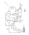
- An internal combustion engine carries in Fig. 1 in total, the reference numeral 10. It comprises several combustion chambers, of which in Fig. 1 only one is represented by the reference numeral 12. This combustion air is supplied via an inlet valve 14 and an intake pipe 16. The combustion exhaust gases are discharged from the combustion chamber 12 via an exhaust valve 18 and an exhaust pipe 20.
- Fuel is supplied to the combustion chamber 12 via a fuel injection device 22 arranged directly on the combustion chamber 12.
- the ignition of the present in the combustion chamber 12 fuel-air mixture is carried out by a spark plug 23, which is connected to an ignition system 25.
- the fuel injector 22 includes a piezo actuator 24 coupled to a valve member (not shown) of the fuel injector 22.
- an ohmic resistor 27 is connected to the piezoelectric actuator 24, an ohmic resistor 27 is connected.
- the fuel injection device 22 is connected to a fuel rail 28 ("rail"). Between the fuel rail 28 and the fuel injection device 22, a check valve 30 is disposed in the high-pressure fuel line 26.
- the fuel rail 28 is supplied with fuel from a high-pressure fuel pump 32.
- the internal combustion engine 10 is the fuel stored in the fuel rail 28 under high pressure.
- the supplied amount of fuel is adjusted by a quantity control valve 34. This can during a delivery cycle of the high-pressure fuel pump 32 whose working space (not shown) with a low-pressure fuel line 36 connect. Thus, during the opening period of the quantity control valve 34, no fuel from the high pressure fuel pump 32 to the fuel rail 28 passes.
- the pressure in the fuel rail 28 is adjusted by a pressure control valve 38. This is connected via a return line 40 with a fuel tank 42.
- An electric fuel pump 44 delivers the fuel from the fuel tank 42 to the low pressure fuel line 36 and further to the high pressure fuel pump 32.
- the engine 10 also includes a controller 46. This controls the fuel injector 22, the ignition system 25, the shut-off valve 30, the mass control valve 34, and the pressure control valve 38.
- the operation of the internal combustion engine 10 is controlled by the control and regulating device according to the in Fig. 2 controlled procedures shown. This is stored as a computer program in the control and regulating device 46.
- the method begins in a start block 48.
- the function of the piezoelectric actuator 24 is monitored.
- malfunctions of the piezoelectric actuator 24 can be detected.
- Such a malfunction includes, for example, a break in the connection between the piezoelectric actuator 24 and the control and regulating device 46.
- a defect in the control device itself, which leads to a malfunction of the piezoelectric actuator 24 can be detected in block 50.
- a malfunction of the piezoelectric actuator 24 can be detected in block 50, for example, by regularly recording the discharge current the piezoelectric actuator 24 is measured during the closing operation. If the connection between the piezoelectric actuator 24 and the control and regulating device 46, for example, interrupted by a cable break or by a dropped cable, the measured discharge current is zero, so that the resulting malfunction of the piezoelectric actuator 24 can be detected immediately.
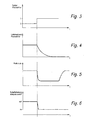
- shut-off valve 30 is closed (block 52). Furthermore, any electric charge which may still be stored in the piezoactuator 24 is discharged via the ohmic resistor 27 (block 54). Finally, in block 56, the pressure control valve 38 and the quantity control valve 34 are activated so that the pressure in the fuel rail 28 drops abruptly.
- a high level of security against unintentional fuel entry into the combustion chamber 12 in case of malfunction of the piezoelectric actuator 24 is created by these measures.
- Fig. 4 shows, it takes a certain time until the charge is discharged from the piezoelectric actuator 24 (see. Fig. 4 ).
- the ohmic resistance 27 must be designed so that during normal operation of the internal combustion engine 10 without malfunction of the piezoelectric actuator 24, the charge in the piezoelectric actuator 24 can be constructed sufficiently quickly that a corresponding rapid actuation of the piezoelectric actuator 24 and with him coupled valve element is possible.
- Fig. 5 how out Fig. 5 can be seen, by the control of the quantity control valve 34 and the pressure control valve 38, a reduction of the pressure in the fuel rail 28 within a period of time is possible, which is significantly shorter than the period which is required for the reduction of the charge in the piezoelectric actuator 24.
- the valve of the fuel injection device 22 is not fully closed, ensures that, if anything, only a little fuel in the combustion chamber 12 of the internal combustion engine 10 can pass.
- This is further assisted by the closing of the shut-off valve 30 (FIG. Fig. 6 ), through which the fuel supply to the fuel injection device 22 is completely interrupted.
- the reduction of the fuel mass flow to the fuel injection device 22 is therefore redundant in the present embodiment.
- Fig. 2 At block 58, it is checked if the fuel injector 22 is fully closed. Under knowledge of the discharge curve of Fig. 4 For example, after a certain time, it can be assumed that the piezoactuator 24 is completely discharged and thus the valve element of the fuel injection device 22 is in the fully closed position. If the answer in block 58 is "yes", the quantity control valve 34 and the pressure control valve 38 are again activated in block 60 in such a way that the normal operating pressure builds up in the fuel manifold 28 (cf. Fig. 5 ). The method ends in an end block 62.
Claims (7)
- Procédé de gestion d'un moteur à combustion interne (10) selon lequel le carburant arrive directement dans au moins une chambre de combustion (12) du moteur à combustion interne (10) par au moins un dispositif d'injection de carburant (22) dont l'élément d'injecteur est déplacé par un actionneur piézo-électrique (24), et selon lequel on surveille le fonctionnement de l'actionneur piézo-électrique (24) et on détecte un défaut de fonctionnement (50),
et en cas de défaut de fonctionnement (50) détecté de l'actionneur piézo-électrique (24), on réduit le débit massique de carburant vers le dispositif d'injection de carburant (22) (52, 56),
le carburant étant fourni par au moins une pompe à carburant (32, 44) à une zone haute pression (28) à laquelle est relié le dispositif d'injection de carburant (22),
caractérisé en ce qu'
en cas de détection de défaut de fonctionnement (50) de l'actionneur piézo-électrique (24), on diminue la pression dans la zone haute pression (28) et
en cas de défaut de fonctionnement (50) détecté, l'actionneur piézo-électrique (24) est mis dans une position de sécurité (54) et on relève la pression dans la zone haute pression (28) de nouveau à un niveau normal lorsque l'actionneur piézo-électrique (24) est dans la position de sécurité. - Procédé selon la revendication 1,
caractérisé en ce que
l'élément d'injecteur du dispositif d'injection de carburant (22) est conduit d'une position ouverte, défectueuse par la décharge de l'actionneur piézo-électrique (24) dans une position de sécurité, fermée (54). - Procédé selon l'une des revendications 1 ou 2,
caractérisé en ce qu'
en cas de défaut de fonctionnement (50) de l'actionneur piézo-électrique (24), détecté, on coupe (52) la liaison de carburant vers le dispositif d'injection de carburant (22). - Programme d'ordinateur
caractérisé en ce qu'
il exécute toutes les étapes du procédé selon l'une des revendications précédentes appliqué à un ordinateur. - Programme d'ordinateur selon la revendication 4,
caractérisé en ce qu'
il est enregistré dans une mémoire, notamment dans une mémoire flash ou une mémoire RAM à ferrites. - Appareil de commande et/ou de régulation (46) pour la gestion d'un moteur à combustion interne (10),
caractérisé en ce qu'
il comprend une mémoire sur laquelle est enregistré un programme d'ordinateur selon l'une des revendications 4 ou 5. - Moteur à combustion interne (10) comportant au moins une pompe à carburant (32, 44), au moins un dispositif d'injection de carburant (22) qui injecte le carburant directement dans au moins une chambre de combustion (24) du moteur à combustion interne (10) et dont l'élément d'injecteur est couplé à un actionneur piézo-électrique (24) et des moyens (46) permettant de détecter un défaut de fonctionnement de l'actionneur piézo-électrique (24),
caractérisé en ce qu'
il comporte un appareil de commande et/ou de régulation (46) selon la revendication 6.
Applications Claiming Priority (3)
| Application Number | Priority Date | Filing Date | Title |
|---|---|---|---|
| DE10148221 | 2001-09-28 | ||
| DE10148221A DE10148221A1 (de) | 2001-09-28 | 2001-09-28 | Verfahren, Computerprogramm sowie Steuer- und/oder Regelgerät zum Betreiben einer Brennkraftmaschine, sowie Brennkraftmaschine |
| PCT/DE2002/002785 WO2003031788A1 (fr) | 2001-09-28 | 2002-07-26 | Procede et dispositif de commande et/ou reglage pour faire fonctionner un moteur a combustion interne a soupapes d'injection de carburant a actionnement piezo-electrique |
Publications (2)
| Publication Number | Publication Date |
|---|---|
| EP1432903A1 EP1432903A1 (fr) | 2004-06-30 |
| EP1432903B1 true EP1432903B1 (fr) | 2008-07-30 |
Family
ID=7700859
Family Applications (1)
| Application Number | Title | Priority Date | Filing Date |
|---|---|---|---|
| EP02760109A Expired - Lifetime EP1432903B1 (fr) | 2001-09-28 | 2002-07-26 | Procede et dispositif de commande et/ou reglage pour faire fonctionner un moteur a combustion interne a soupapes d'injection de carburant a actionnement piezo-electrique |
Country Status (5)
| Country | Link |
|---|---|
| US (1) | US6918379B2 (fr) |
| EP (1) | EP1432903B1 (fr) |
| JP (1) | JP4319909B2 (fr) |
| DE (2) | DE10148221A1 (fr) |
| WO (1) | WO2003031788A1 (fr) |
Families Citing this family (10)
| Publication number | Priority date | Publication date | Assignee | Title |
|---|---|---|---|---|
| US7428893B2 (en) * | 2004-11-12 | 2008-09-30 | Caterpillar Inc | Electronic flow control valve |
| JP2007056849A (ja) * | 2005-08-26 | 2007-03-08 | Toyota Motor Corp | エンジンの制御装置 |
| DE102005053405B4 (de) | 2005-11-09 | 2019-01-03 | Robert Bosch Gmbh | Verfahren und Vorrichtung zur Überwachung eines Kraftstoffzumesssystems |
| US7562561B2 (en) * | 2007-04-13 | 2009-07-21 | Honda Motor Co., Ltd. | Intake air leak determination system and method |
| US7661410B1 (en) * | 2008-08-18 | 2010-02-16 | Caterpillar Inc. | Fluid leak limiter |
| JP5262764B2 (ja) * | 2009-01-29 | 2013-08-14 | 株式会社デンソー | インジェクタ |
| DE102009014072B4 (de) * | 2009-03-20 | 2014-09-25 | Continental Automotive Gmbh | Common-Rail-Einspritzsystem sowie Verfahren zur Druckentlastung eines Common-Rail-Einspritzsystems |
| DE102010029493A1 (de) * | 2010-05-31 | 2011-12-01 | Robert Bosch Gmbh | Vorrichtung zum Prüfen von Kraftstoffinjektoren sowie entsprechendes Verfahren |
| DE102011001299B4 (de) | 2011-03-16 | 2015-06-25 | L'orange Gmbh | Verfahren zur Funktionsüberprüfung von Hubkolben-Brennkraftmaschinen, insbesondere Diesel-Brennkraftmaschinen |
| US11914408B2 (en) | 2022-01-21 | 2024-02-27 | Hamilton Sundstrand Corporation | Active flow control system |
Family Cites Families (6)
| Publication number | Priority date | Publication date | Assignee | Title |
|---|---|---|---|---|
| DE19536109A1 (de) * | 1995-09-28 | 1997-04-03 | Bosch Gmbh Robert | Verfahren und Vorrichtung zur Überwachung eines Kraftstoffzumeßsystems |
| DE19604552B4 (de) * | 1996-02-08 | 2007-10-31 | Robert Bosch Gmbh | Verfahren und Vorrichtung zur Steuerung einer Brennkraftmaschine |
| DE19711903C2 (de) * | 1997-03-21 | 1999-03-18 | Siemens Ag | Vorrichtung und Verfahren zum Ansteuern eines piezogesteuerten Kraftstoffeinspritzventils |
| DE19719631A1 (de) * | 1997-05-09 | 1998-09-17 | Daimler Benz Ag | Verfahren und Vorrichtung zur Vermeidung von Schäden an einer Dieselbrennkraftmaschine durch unzulässig hohe Verbrennungsdrücke |
| DE19810525C2 (de) | 1998-03-11 | 2000-07-27 | Siemens Ag | Verfahren und Vorrichtung zum Ansteuern kapazitiver Stellglieder |
| DE19854306A1 (de) * | 1998-11-25 | 2000-06-08 | Bosch Gmbh Robert | Steller mit kapazitivem Element |
-
2001
- 2001-09-28 DE DE10148221A patent/DE10148221A1/de not_active Ceased
-
2002
- 2002-07-26 US US10/491,404 patent/US6918379B2/en not_active Expired - Fee Related
- 2002-07-26 DE DE50212582T patent/DE50212582D1/de not_active Expired - Lifetime
- 2002-07-26 EP EP02760109A patent/EP1432903B1/fr not_active Expired - Lifetime
- 2002-07-26 JP JP2003534741A patent/JP4319909B2/ja not_active Expired - Fee Related
- 2002-07-26 WO PCT/DE2002/002785 patent/WO2003031788A1/fr active IP Right Grant
Also Published As
| Publication number | Publication date |
|---|---|
| WO2003031788A1 (fr) | 2003-04-17 |
| JP4319909B2 (ja) | 2009-08-26 |
| DE50212582D1 (de) | 2008-09-11 |
| US20050016502A1 (en) | 2005-01-27 |
| DE10148221A1 (de) | 2003-07-31 |
| EP1432903A1 (fr) | 2004-06-30 |
| US6918379B2 (en) | 2005-07-19 |
| JP2005504913A (ja) | 2005-02-17 |
Similar Documents
| Publication | Publication Date | Title |
|---|---|---|
| EP1268999B1 (fr) | Procede de determination de la pression de rampe d'une soupape d'injection comprenant un actionneur piezo-electrique | |
| DE102006047181B4 (de) | Kraftstoffeinspritzsystem, das zum Gewährleisten einer verbesserten Zuverlässigkeit zum Diagnostizieren eines Ventils ausgelegt ist | |
| DE4425388B4 (de) | Steuergerät | |
| DE19626689C1 (de) | Verfahren und Vorrichtung zur Überwachung eines Einspritzsystems | |
| DE60017307T2 (de) | Common-Rail-Kraftstoffeinspritzsystem | |
| DE19520300A1 (de) | Einrichtung zur Erkennung eines Lecks in einem Kraftstoffversorgungssystem | |
| EP1735673B1 (fr) | Procede pour surveiller un dispositif d'alimentation en carburant d'un moteur a combustion interne | |
| EP0666416B1 (fr) | Dispositif d'injection pour moteurs à combustion interne, en particulier pour un moteur diesel, et méthode de surveillance de ce dispositif | |
| EP1664511B1 (fr) | Procede de determination de la tension de commande d'un actionneur piezoelectrique d'une soupape d'injection | |
| EP1432903B1 (fr) | Procede et dispositif de commande et/ou reglage pour faire fonctionner un moteur a combustion interne a soupapes d'injection de carburant a actionnement piezo-electrique | |
| EP1348072B1 (fr) | Procede, programme informatique et appareil de commande et/ou de reglage permettant d'exploiter un moteur a combustion interne et moteur a combustion interne | |
| DE10351893A1 (de) | Verfahren zum Betreiben einer Brennkraftmaschine | |
| DE102013101905A1 (de) | Kraftstoffeinspritzfehlererfassungsvorrichtung | |
| EP0764777B1 (fr) | Méthode et appareil pour la commande d'un moteur à combustion interne | |
| DE102005043684A1 (de) | Kraftstoffdruckregelung bei Schubabschaltung | |
| DE102008044047B4 (de) | Verfahren und Vorrichtung zur Steuerung einer Brennkraftmaschine | |
| DE102007044001B4 (de) | Verfahren zur Steuerung eines Kraftstoffeinspritzsystems einer Brennkraftmaschine | |
| WO2008003717A1 (fr) | Procédé pour diminuer la pression du rail dans un système d'injection à rail commun | |
| DE10028353A1 (de) | Verfahren zur Überprüfung eines kapazitiven Stellgliedes | |
| WO2001051791A1 (fr) | Procede permettant de faire fonctionner un moteur a combustion interne | |
| DE102015225504A1 (de) | Verfahren zur Fehlerkompensation einer Kraftstoffeinspritzmenge beim Betrieb einer Brennkraftmaschine | |
| WO2010106037A1 (fr) | Dispositif et procédé de décharge de pression d'un système d'injection | |
| EP1327762B1 (fr) | Procédé, programme informatique et dispositif de commande et/ou de réglage pour le fonctionnement d'un moteur à combustion interne, ainsi qu'un moteur à combustion interne | |
| EP3337962B1 (fr) | Dispositif d'alimentation en carburant pour injection moteur et post-traitement des gaz d'échappement | |
| EP1530677B1 (fr) | Procede et dispositif de fonctionnement d'un actionneur pourvu d'un element capacitif |
Legal Events
| Date | Code | Title | Description |
|---|---|---|---|
| PUAI | Public reference made under article 153(3) epc to a published international application that has entered the european phase |
Free format text: ORIGINAL CODE: 0009012 |
|
| 17P | Request for examination filed |
Effective date: 20040428 |
|
| AK | Designated contracting states |
Kind code of ref document: A1 Designated state(s): AT BE BG CH CY CZ DE DK EE ES FI FR GB GR IE IT LI LU MC NL PT SE SK TR |
|
| AX | Request for extension of the european patent |
Extension state: AL LT LV MK RO SI |
|
| 17Q | First examination report despatched |
Effective date: 20070920 |
|
| GRAP | Despatch of communication of intention to grant a patent |
Free format text: ORIGINAL CODE: EPIDOSNIGR1 |
|
| GRAS | Grant fee paid |
Free format text: ORIGINAL CODE: EPIDOSNIGR3 |
|
| GRAA | (expected) grant |
Free format text: ORIGINAL CODE: 0009210 |
|
| AK | Designated contracting states |
Kind code of ref document: B1 Designated state(s): DE FR IT |
|
| REF | Corresponds to: |
Ref document number: 50212582 Country of ref document: DE Date of ref document: 20080911 Kind code of ref document: P |
|
| PLBE | No opposition filed within time limit |
Free format text: ORIGINAL CODE: 0009261 |
|
| STAA | Information on the status of an ep patent application or granted ep patent |
Free format text: STATUS: NO OPPOSITION FILED WITHIN TIME LIMIT |
|
| 26N | No opposition filed |
Effective date: 20090506 |
|
| PGFP | Annual fee paid to national office [announced via postgrant information from national office to epo] |
Ref country code: FR Payment date: 20130719 Year of fee payment: 12 |
|
| PGFP | Annual fee paid to national office [announced via postgrant information from national office to epo] |
Ref country code: IT Payment date: 20130729 Year of fee payment: 12 |
|
| REG | Reference to a national code |
Ref country code: FR Ref legal event code: ST Effective date: 20150331 |
|
| PG25 | Lapsed in a contracting state [announced via postgrant information from national office to epo] |
Ref country code: IT Free format text: LAPSE BECAUSE OF NON-PAYMENT OF DUE FEES Effective date: 20140726 |
|
| PG25 | Lapsed in a contracting state [announced via postgrant information from national office to epo] |
Ref country code: FR Free format text: LAPSE BECAUSE OF NON-PAYMENT OF DUE FEES Effective date: 20140731 |
|
| PGFP | Annual fee paid to national office [announced via postgrant information from national office to epo] |
Ref country code: DE Payment date: 20150925 Year of fee payment: 14 |
|
| REG | Reference to a national code |
Ref country code: DE Ref legal event code: R119 Ref document number: 50212582 Country of ref document: DE |
|
| PG25 | Lapsed in a contracting state [announced via postgrant information from national office to epo] |
Ref country code: DE Free format text: LAPSE BECAUSE OF NON-PAYMENT OF DUE FEES Effective date: 20170201 |