EP1432014A2 - Methode und Apparat zur Spülung einer Vakuum-Kammer - Google Patents
Methode und Apparat zur Spülung einer Vakuum-Kammer Download PDFInfo
- Publication number
- EP1432014A2 EP1432014A2 EP03257642A EP03257642A EP1432014A2 EP 1432014 A2 EP1432014 A2 EP 1432014A2 EP 03257642 A EP03257642 A EP 03257642A EP 03257642 A EP03257642 A EP 03257642A EP 1432014 A2 EP1432014 A2 EP 1432014A2
- Authority
- EP
- European Patent Office
- Prior art keywords
- load
- purging
- lock chamber
- lock
- gas diffusion
- Prior art date
- Legal status (The legal status is an assumption and is not a legal conclusion. Google has not performed a legal analysis and makes no representation as to the accuracy of the status listed.)
- Withdrawn
Links
Images


Classifications
-
- H10P95/00—
-
- H10P72/0402—
Definitions
- the present invention relates generally to load-lock chambers used in the processing of semiconductor wafers. More specifically, the present invention relates to an apparatus and methodology for purging a load-lock chamber with an inert gas.
- a semiconductor processing system will often include a load-lock chamber, a central handler chamber, and a processing chamber configured together and isolated by pneumatic gate valves.
- the load-lock chamber receives a semiconductor wafer.
- the gas in the load-lock chamber is evacuated and replaced with a gas that will permit a pressure environment to be created, which is generally the same as the process chamber.
- the gate valve is opened and the wafer is moved from the load-lock chamber to the processing chamber via the central handler. Following processing, the gate valve is opened and the wafer is returned to the load-lock chamber. Then the gate valve is closed and the gas within the load-lock chamber is evacuated and replaced with an inert gas, such as nitrogen, which is used to return the load lock to atmospheric pressure.
- the inert gas may be used to purge the load-lock chamber while the wafer is being moved into and out of the chamber.
- One method of introducing the purge gas to the load-lock chamber is with one or more nozzles.
- the use of purge gas nozzles produce turbulent flows and eddy regions that results in high concentration of oxygen and moisture within the purged region.
- the introduction of moisture is particularly troublesome, as it tends to adsorb on the interior surfaces of the chamber. This adsorbed moisture may then be slowly released during the chamber evacuation process, and subsequently transported to the wafer process chamber.
- a purging apparatus in one aspect of the invention, includes a load-lock having a vacuum door and an atmospheric door and defining a load-lock chamber.
- a purging gas diffusion device is disposed in the load-lock chamber proximate the vacuum door and distal from the atmospheric door.
- the purging gas diffusion device includes a porous section. The pores in the porous section diffuse the purge gas therethrough in a purge flow that travels through the load-lock chamber in flow direction from the vacuum door to the atmospheric door.
- a method for purging a load lock includes providing a load-lock having a vacuum door and an atmospheric door and defining a load-lock chamber, a purging gas diffusion device disposed in the load-lock chamber proximate the vacuum door and distal from the atmospheric door, the purging gas diffusion device including a plurality of pores.
- the method includes diffusing purge gas through the pores of the purging gas diffusing device; creating a purge gas flow within the load-lock chamber to remove ambient air and prevent entrainment of air during wafer transport.
- the present invention also provides purging apparatus for a load-lock, the apparatus comprising means for diffusing a purge gas through the load-lock, said means comprising a porous section through which the purge gas enters the load-lock.
- Purging apparatus 10 includes a load lock 12 which may be used in, for example, a semiconductor wafer film deposition process.
- the purpose of load lock 12 is to minimize the introduction of ambient air contaminants into the semiconductor tool and to balance pressures to facilitate transport of wafers between the cleanroom and the process chamber.
- load lock 12 may be used in a semiconductor process, it may be used with any process in which air or moisture could degrade the quality of a film deposition, and in which the regulation of air content and moisture concentration is contemplated
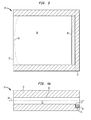
- Purging apparatus 10 includes an atmospheric door 14 which is connected to load lock 12 and can be opened or closed as desired to expose the interior of load lock 12 to the ambient atmosphere. Also connected to load lock 12 is a vacuum door which has been removed to facilitate understanding of the drawing.
- Fig. 1 shows a load lock chamber 18 partially exposed to show purging gas diffusion device 16 disposed within the load lock chamber 18 and connected to load lock 12.
- Purging gas diffusion device 16 is located preferably in a horizontal position with respect to the operational position of load lock 12, and purging gas diffusion device 16 is located proximate to the vacuum door and distal from the atmospheric door 14.
- Load lock 12 may be constructed of any suitable material and aluminum is an example of one such material.
- a side view of the load lock purging system of Fig. 1 is shown.
- the load lock chamber 18 runs the entire length of the purging apparatus 10, and through load lock chamber 18 to facilitate moving, for example, a semiconductor wafer along through load lock chamber 18 of load lock 12 and into, for example, a process chamber.
- the load lock chamber is capable of having an interior pressure that is substantially equal to a vacuum condition, as during a semiconductor process.
- a top schematic view of the load lock purging system 10 is shown.
- vacuum door 15 is shown closed, as would occur during the purging process.
- purging gas diffusion device 16 diffuses an inert gas, which preferably includes one of N 2 , Ar and He, and more preferably N 2 .
- the operation of the present invention is independent of the type of purged gas selected.
- the diffusion of the purged gas by the purging gas diffusion device 16 produces a purge flow having a purge flow boundary 20.
- this purge flow boundary 20 is typically of a laminar flow type. Therefore, the purged gas flows through the entire load lock chamber 18 and purges ambient air via atmospheric door exit 22, since the atmospheric door is opened prior to purging.
- load lock chamber 18 of load lock 12 includes a through-path portion 24 and an offset channel portion 26, located in the region created by curb 27. It is in this offset channel portion 26 into which purging gas diffusion device 16 is disposed.
- the purging gas diffusion device 16 is placed such that it is substantially in the offset channel portion 26 and does not extend substantially into the through path portion 24. This placement prevents purging gas diffusion device 16 from interfering with, for example, a semiconductor wafer as it travels through-path portion 24 of load lock chamber 18.
- purging gas diffusion device 16 is important to prevent obstruction of products passing through the load-lock chamber 18 in general, and particularly through-path portion 24. Again, for orientation purposes, since the purging of load lock chamber 18 occurs in a purging direction from vacuum door 15 to atmospheric door exit 22, purging gas diffusion device 16 is placed such that it is at a rear section of load lock chamber 18 and proximate the vacuum door 15. As purging gas diffusion device 16 diffuses the purge gas therethrough, purge gas proceeds from the offset channel portion 26 and generally along through-path portion 24 in the purging direction, thereby purging load lock chamber 18 with the desired purge gas.
- Fig. 5 is a perspective view of an exemplary purging gas diffusion device.
- Purging gas diffusion device 16 is constructed to receive a flow of purge gas and diffuse it through a porous material of which purging gas diffusion device 16 is constructed.
- Purge gas diffusion device includes a hollow tubular member or portion 30 for receiving a purge gas and diffusing the purge gas through the pores of the hollow tubular member.
- tubular member 30 is a frit made of 3/16th inch stainless steel and includes a center tubular portion 30 and end portions 32a and 32b, which are connected to tubular portion 30.
- tubular portion 30 is shown as a tube, it is contemplated that other structures having various shapes that permit the flow of gas therethrough may be suitably employed.
- End portion 32a defines a purge gas inlet 34 as well as a mounting channel 36a.
- End portion 32b similarly includes a mounting channel 36b such that purging gas diffusion device 16 may be secured to the load lock 12 (of Fig. 1).
- FIG. 6 another perspective view of the purge gas diffusion device 16 of Fig. 5 is shown.
- securing channels 36a and 36b are shown from the reverse angle to illustrate those locations adapted to receive screws or other securing mechanisms in order to secure the entire purging gas diffusion device 16, including tubular portion 30, to the load lock.
- tubular portion 30 is constructed of a porous material, such that the purged gas may be diffused therethrough.
- the average pore size is substantially 100 microns, i.e., to prevent particles having an approximate diameter of 100 microns. More preferably, the average pore size for tubular portion 30 has less than 100 microns. However, any suitable pore size feasible for the particular operation is contemplated.
- the pores of tubular portion 30 may also serve to filter any purge gas as it enters the load lock.
- Purge gas diffusion device 16 is adapted to receive the purge gas such as nitrogen into purge gas inlet 34 located in end portion 32a. Nitrogen or other purge gas enters interior chamber 31 and is diffused through the pores of tubular portion 30. Because end portion 32b prevents purge gas from exiting through that end of tubular portion 30, as the purge gas fills purge gas diffusion device 16, purge gas will come through the pores and not through the ends of tubular portion 30.
- Fig. 8 is a graph illustrating oxygen concentration data taken from a purge optimization test. The test was conducted by comparing a nozzle to the purge gas dispersing device for completeness of purging of unwanted gaseous oxygen. In the first part of the test, a spray nozzle was placed at a central location of the load lock chamber 18. Purge gas was then sprayed through the nozzle. Oxygen concentration levels were then taken at nine locations within the load lock chamber, the locations being shown in the side legend. The locations correspond to the relative orientation positions in the load lock, with the front corresponding to the side by the atmospheric door, and with the rear corresponding to the side near the vacuum door. The locations represented are RL, RC, RR, CL, CC, CR, FL, FC and FR. They are defined as follows in a conventional manner. RL rear left RC rear center RR rear right CL center left CC center center CR center right FL front left FC front center FR front right
- Each of the test locations were approximately 161 mm away from each other and offset between 50 mm and 75 mm from the interior wall of the load lock chamber.
- the readings for the center nozzle that is, when the nozzle provides the purge gas in the center of the load lock chamber, reveal oxygen concentrations exceeding 100,000 ppm (40) for all nine locations within the load lock chamber.
- a diffuser device was used and was placed in the rear (corresponding to the offset channel portion) of the load lock chamber. Purge gas was diffused through the rear diffuser and again oxygen concentration measurements were taken at the same locations in the load lock chamber.
- the rear diffuser readings (collectively 42) indicated oxygen concentrations of less than 0.1 PPM, for all nine chambers position locations as shown in the graph at 44. This represents a reduction in the oxygenation concentration in parts per million by a factor of six when using a porous diffuser at a rear of the load lock chamber and generating the purge gas front from that location.
- Other tests revealed oxygen concentration levels in the range from about .1 PPM to under 100,000 PPM.
- a method for purging a load lock includes providing a load-lock having a vacuum door and an atmospheric door and defining a load-lock chamber, a purging gas diffusion device disposed in the load-lock chamber proximate the vacuum door and distal from the atmospheric door, the purging gas diffusion device including a plurality of pores.
- the method includes diffusing purge gas through the pores of the purging gas diffusing device; creating a purge gas flow within the load-lock chamber to remove ambient air having at least one ambient gas; and purging the load-lock with the purge gas to create an ambient gas concentration of the ambient gas.
- suitable flow rates of the purge gas, alternative materials for the purge gas diffusion device, and optimal load lock heights are to be considered to be part of the present invention.
Landscapes
- Container, Conveyance, Adherence, Positioning, Of Wafer (AREA)
- Physical Vapour Deposition (AREA)
- Chemical Vapour Deposition (AREA)
Applications Claiming Priority (2)
| Application Number | Priority Date | Filing Date | Title |
|---|---|---|---|
| US10/322,211 US20040118343A1 (en) | 2002-12-18 | 2002-12-18 | Vacuum chamber load lock purging method and apparatus |
| US322211 | 2002-12-18 |
Publications (2)
| Publication Number | Publication Date |
|---|---|
| EP1432014A2 true EP1432014A2 (de) | 2004-06-23 |
| EP1432014A3 EP1432014A3 (de) | 2005-08-17 |
Family
ID=32393017
Family Applications (1)
| Application Number | Title | Priority Date | Filing Date |
|---|---|---|---|
| EP03257642A Withdrawn EP1432014A3 (de) | 2002-12-18 | 2003-12-04 | Methode und Apparat zur Spülung einer Vakuum-Kammer |
Country Status (5)
| Country | Link |
|---|---|
| US (1) | US20040118343A1 (de) |
| EP (1) | EP1432014A3 (de) |
| JP (1) | JP2004228562A (de) |
| KR (1) | KR20040054520A (de) |
| TW (1) | TW200509196A (de) |
Families Citing this family (9)
| Publication number | Priority date | Publication date | Assignee | Title |
|---|---|---|---|---|
| JP2007048848A (ja) * | 2005-08-08 | 2007-02-22 | Hitachi Kokusai Electric Inc | 基板処理装置 |
| US20100119351A1 (en) * | 2008-11-13 | 2010-05-13 | Wafertech, Llc | Method and system for venting load lock chamber to a desired pressure |
| WO2012077547A1 (ja) * | 2010-12-09 | 2012-06-14 | 東京エレクトロン株式会社 | ロードロック装置 |
| WO2014041656A1 (ja) * | 2012-09-13 | 2014-03-20 | 株式会社日立ハイテクノロジーズ | 真空処理装置 |
| KR102135409B1 (ko) * | 2016-11-09 | 2020-07-17 | 주식회사 원익아이피에스 | 로드락챔버 및 이를 포함하는 기판처리장치 |
| TWI840362B (zh) * | 2018-06-04 | 2024-05-01 | 荷蘭商Asm Ip私人控股有限公司 | 水氣降低的晶圓處置腔室 |
| FR3092879B1 (fr) * | 2019-02-14 | 2021-02-19 | Pfeiffer Vacuum | Pompe à vide primaire de type sèche |
| KR20210071334A (ko) * | 2019-12-06 | 2021-06-16 | 주식회사 아바코 | 스퍼터링 시스템 |
| CN115642113A (zh) * | 2022-09-27 | 2023-01-24 | 拓荆科技股份有限公司 | 一种共通冲洗路径的搬送组件 |
Family Cites Families (9)
| Publication number | Priority date | Publication date | Assignee | Title |
|---|---|---|---|---|
| JP3147325B2 (ja) * | 1994-08-17 | 2001-03-19 | 東京エレクトロン株式会社 | 半導体ウエハ処理装置 |
| JP3525039B2 (ja) * | 1997-10-06 | 2004-05-10 | 東京応化工業株式会社 | 減圧処理装置 |
| JP3367421B2 (ja) * | 1998-04-16 | 2003-01-14 | 東京エレクトロン株式会社 | 被処理体の収納装置及び搬出入ステージ |
| JP2000256083A (ja) * | 1999-03-05 | 2000-09-19 | Toshiba Ceramics Co Ltd | 半導体ウエハ処理装置用多孔質体 |
| US6178660B1 (en) * | 1999-08-03 | 2001-01-30 | International Business Machines Corporation | Pass-through semiconductor wafer processing tool and process for gas treating a moving semiconductor wafer |
| US6734950B2 (en) * | 2000-06-13 | 2004-05-11 | Canon Kabushiki Kaisha | Load-lock chamber and exposure apparatus using the same |
| JP2002075856A (ja) * | 2000-06-13 | 2002-03-15 | Canon Inc | ロードロックチャンバ及びそれを用いた露光装置 |
| US6672864B2 (en) * | 2001-08-31 | 2004-01-06 | Applied Materials, Inc. | Method and apparatus for processing substrates in a system having high and low pressure areas |
| US20040069409A1 (en) * | 2002-10-11 | 2004-04-15 | Hippo Wu | Front opening unified pod door opener with dust-proof device |
-
2002
- 2002-12-18 US US10/322,211 patent/US20040118343A1/en not_active Abandoned
-
2003
- 2003-11-27 TW TW092133338A patent/TW200509196A/zh unknown
- 2003-12-04 EP EP03257642A patent/EP1432014A3/de not_active Withdrawn
- 2003-12-16 JP JP2003418065A patent/JP2004228562A/ja active Pending
- 2003-12-16 KR KR1020030092074A patent/KR20040054520A/ko not_active Withdrawn
Also Published As
| Publication number | Publication date |
|---|---|
| TW200509196A (en) | 2005-03-01 |
| EP1432014A3 (de) | 2005-08-17 |
| KR20040054520A (ko) | 2004-06-25 |
| US20040118343A1 (en) | 2004-06-24 |
| JP2004228562A (ja) | 2004-08-12 |
Similar Documents
| Publication | Publication Date | Title |
|---|---|---|
| TWI794765B (zh) | 用於基板容器之歧管 | |
| EP1432014A2 (de) | Methode und Apparat zur Spülung einer Vakuum-Kammer | |
| TW201021626A (en) | Surface processing apparatus | |
| JPH10223719A (ja) | 基板搬送装置、基板処理装置および基板搬送方法 | |
| JP2681576B2 (ja) | 加工物を周囲空気を排除した特定の選択ガスの雰囲気中で処理するための装置及び方法 | |
| US20230377925A1 (en) | Purge flow distribution system for a substrate container and method for performing the same | |
| JP3071320B2 (ja) | 真空装置 | |
| JP2607572B2 (ja) | 荷電粒子を用いる分析装置および方法 | |
| TWI884667B (zh) | 擴散器、具有擴散器之前開式晶圓容器、及使用容器之方法 | |
| JP4414869B2 (ja) | 真空処理装置 | |
| KR930007610Y1 (ko) | 가스 배출 장치 | |
| US20060169318A1 (en) | System, apparatus and method for contaminant reduction in semiconductor device fabrication equipment components | |
| JPH07161688A (ja) | エッチング装置 | |
| WO2024257710A1 (ja) | レーザ装置用フード、レーザ加工装置及びレーザ加工方法 | |
| WO2025072067A1 (en) | Method and assembly for creating a molecular beam | |
| JP2025509795A (ja) | レーザアブレーション試料処理のための大気パージシステムおよび方法 | |
| JPH08279471A (ja) | 半導体製造方法 | |
| JP2003218042A (ja) | ガス供給方法、ガス逆拡散防止方法、ガス逆拡散防止装置、ガス逆拡散防止機構付き操作弁、ガス逆拡散防止機構付き気化器、液体材料気化供給方法と液体材料気化供給装置、及び半導体製造装置におけるガス供給方法と半導体製造装置 |
Legal Events
| Date | Code | Title | Description |
|---|---|---|---|
| PUAI | Public reference made under article 153(3) epc to a published international application that has entered the european phase |
Free format text: ORIGINAL CODE: 0009012 |
|
| AK | Designated contracting states |
Kind code of ref document: A2 Designated state(s): AT BE BG CH CY CZ DE DK EE ES FI FR GB GR HU IE IT LI LU MC NL PT RO SE SI SK TR |
|
| AX | Request for extension of the european patent |
Extension state: AL LT LV MK |
|
| PUAL | Search report despatched |
Free format text: ORIGINAL CODE: 0009013 |
|
| AK | Designated contracting states |
Kind code of ref document: A3 Designated state(s): AT BE BG CH CY CZ DE DK EE ES FI FR GB GR HU IE IT LI LU MC NL PT RO SE SI SK TR |
|
| AX | Request for extension of the european patent |
Extension state: AL LT LV MK |
|
| 17P | Request for examination filed |
Effective date: 20060117 |
|
| AKX | Designation fees paid |
Designated state(s): AT BE BG CH CY CZ DE DK EE ES FI FR GB GR HU IE IT LI LU MC NL PT RO SE SI SK TR |
|
| 17Q | First examination report despatched |
Effective date: 20060213 |
|
| RAP1 | Party data changed (applicant data changed or rights of an application transferred) |
Owner name: BOC EDWARDS, INC. |
|
| RAP1 | Party data changed (applicant data changed or rights of an application transferred) |
Owner name: EDWARDS VACUUM, INC. |
|
| RTI1 | Title (correction) |
Free format text: VACUUM CHAMBER PURGING METHOD AND APPARATUS |
|
| GRAP | Despatch of communication of intention to grant a patent |
Free format text: ORIGINAL CODE: EPIDOSNIGR1 |
|
| STAA | Information on the status of an ep patent application or granted ep patent |
Free format text: STATUS: THE APPLICATION IS DEEMED TO BE WITHDRAWN |
|
| 18D | Application deemed to be withdrawn |
Effective date: 20090701 |