EP1431547A2 - Procédé et dispositif pour déterminer le débit du gaz d'échappement recirculé dans un moteur à combustion interne - Google Patents
Procédé et dispositif pour déterminer le débit du gaz d'échappement recirculé dans un moteur à combustion interne Download PDFInfo
- Publication number
- EP1431547A2 EP1431547A2 EP03028160A EP03028160A EP1431547A2 EP 1431547 A2 EP1431547 A2 EP 1431547A2 EP 03028160 A EP03028160 A EP 03028160A EP 03028160 A EP03028160 A EP 03028160A EP 1431547 A2 EP1431547 A2 EP 1431547A2
- Authority
- EP
- European Patent Office
- Prior art keywords
- mass flow
- exhaust gas
- gas recirculation
- combustion engine
- internal combustion
- Prior art date
- Legal status (The legal status is an assumption and is not a legal conclusion. Google has not performed a legal analysis and makes no representation as to the accuracy of the status listed.)
- Granted
Links
Images
Classifications
-
- F—MECHANICAL ENGINEERING; LIGHTING; HEATING; WEAPONS; BLASTING
- F02—COMBUSTION ENGINES; HOT-GAS OR COMBUSTION-PRODUCT ENGINE PLANTS
- F02D—CONTROLLING COMBUSTION ENGINES
- F02D21/00—Controlling engines characterised by their being supplied with non-airborne oxygen or other non-fuel gas
- F02D21/06—Controlling engines characterised by their being supplied with non-airborne oxygen or other non-fuel gas peculiar to engines having other non-fuel gas added to combustion air
- F02D21/08—Controlling engines characterised by their being supplied with non-airborne oxygen or other non-fuel gas peculiar to engines having other non-fuel gas added to combustion air the other gas being the exhaust gas of engine
-
- F—MECHANICAL ENGINEERING; LIGHTING; HEATING; WEAPONS; BLASTING
- F02—COMBUSTION ENGINES; HOT-GAS OR COMBUSTION-PRODUCT ENGINE PLANTS
- F02D—CONTROLLING COMBUSTION ENGINES
- F02D41/00—Electrical control of supply of combustible mixture or its constituents
- F02D41/0025—Controlling engines characterised by use of non-liquid fuels, pluralities of fuels, or non-fuel substances added to the combustible mixtures
- F02D41/0047—Controlling exhaust gas recirculation [EGR]
- F02D41/0065—Specific aspects of external EGR control
- F02D41/0072—Estimating, calculating or determining the EGR rate, amount or flow
-
- F—MECHANICAL ENGINEERING; LIGHTING; HEATING; WEAPONS; BLASTING
- F02—COMBUSTION ENGINES; HOT-GAS OR COMBUSTION-PRODUCT ENGINE PLANTS
- F02D—CONTROLLING COMBUSTION ENGINES
- F02D41/00—Electrical control of supply of combustible mixture or its constituents
- F02D41/24—Electrical control of supply of combustible mixture or its constituents characterised by the use of digital means
- F02D41/2406—Electrical control of supply of combustible mixture or its constituents characterised by the use of digital means using essentially read only memories
- F02D41/2425—Particular ways of programming the data
- F02D41/2429—Methods of calibrating or learning
- F02D41/2451—Methods of calibrating or learning characterised by what is learned or calibrated
-
- F—MECHANICAL ENGINEERING; LIGHTING; HEATING; WEAPONS; BLASTING
- F02—COMBUSTION ENGINES; HOT-GAS OR COMBUSTION-PRODUCT ENGINE PLANTS
- F02B—INTERNAL-COMBUSTION PISTON ENGINES; COMBUSTION ENGINES IN GENERAL
- F02B29/00—Engines characterised by provision for charging or scavenging not provided for in groups F02B25/00, F02B27/00 or F02B33/00 - F02B39/00; Details thereof
- F02B29/04—Cooling of air intake supply
- F02B29/0406—Layout of the intake air cooling or coolant circuit
-
- F—MECHANICAL ENGINEERING; LIGHTING; HEATING; WEAPONS; BLASTING
- F02—COMBUSTION ENGINES; HOT-GAS OR COMBUSTION-PRODUCT ENGINE PLANTS
- F02D—CONTROLLING COMBUSTION ENGINES
- F02D2200/00—Input parameters for engine control
- F02D2200/02—Input parameters for engine control the parameters being related to the engine
- F02D2200/04—Engine intake system parameters
- F02D2200/0406—Intake manifold pressure
-
- F—MECHANICAL ENGINEERING; LIGHTING; HEATING; WEAPONS; BLASTING
- F02—COMBUSTION ENGINES; HOT-GAS OR COMBUSTION-PRODUCT ENGINE PLANTS
- F02D—CONTROLLING COMBUSTION ENGINES
- F02D41/00—Electrical control of supply of combustible mixture or its constituents
- F02D41/24—Electrical control of supply of combustible mixture or its constituents characterised by the use of digital means
- F02D41/2406—Electrical control of supply of combustible mixture or its constituents characterised by the use of digital means using essentially read only memories
- F02D41/2425—Particular ways of programming the data
- F02D41/2429—Methods of calibrating or learning
- F02D41/2441—Methods of calibrating or learning characterised by the learning conditions
-
- F—MECHANICAL ENGINEERING; LIGHTING; HEATING; WEAPONS; BLASTING
- F02—COMBUSTION ENGINES; HOT-GAS OR COMBUSTION-PRODUCT ENGINE PLANTS
- F02M—SUPPLYING COMBUSTION ENGINES IN GENERAL WITH COMBUSTIBLE MIXTURES OR CONSTITUENTS THEREOF
- F02M26/00—Engine-pertinent apparatus for adding exhaust gases to combustion-air, main fuel or fuel-air mixture, e.g. by exhaust gas recirculation [EGR] systems
- F02M26/02—EGR systems specially adapted for supercharged engines
- F02M26/04—EGR systems specially adapted for supercharged engines with a single turbocharger
- F02M26/05—High pressure loops, i.e. wherein recirculated exhaust gas is taken out from the exhaust system upstream of the turbine and reintroduced into the intake system downstream of the compressor
-
- Y—GENERAL TAGGING OF NEW TECHNOLOGICAL DEVELOPMENTS; GENERAL TAGGING OF CROSS-SECTIONAL TECHNOLOGIES SPANNING OVER SEVERAL SECTIONS OF THE IPC; TECHNICAL SUBJECTS COVERED BY FORMER USPC CROSS-REFERENCE ART COLLECTIONS [XRACs] AND DIGESTS
- Y02—TECHNOLOGIES OR APPLICATIONS FOR MITIGATION OR ADAPTATION AGAINST CLIMATE CHANGE
- Y02T—CLIMATE CHANGE MITIGATION TECHNOLOGIES RELATED TO TRANSPORTATION
- Y02T10/00—Road transport of goods or passengers
- Y02T10/10—Internal combustion engine [ICE] based vehicles
- Y02T10/40—Engine management systems
Definitions
- the present invention relates to a method and an apparatus for determining the Exhaust gas recirculation mass flow of an internal combustion engine, for example a diesel engine.
- the present invention relates to such a method and such Device, with the help of the information thus obtained about the exhaust gas recirculation mass flow the exhaust gas recirculation rate can be determined correctly.
- an operating parameter is the exhaust gas recirculation mass flow in an internal combustion engine with exhaust gas recirculation, d. H. the mass flow of that emitted by the internal combustion engine Exhaust gas, which is fed to a mixing point via an exhaust gas recirculation line, where the exhaust gas is mixed with fresh air sucked in to the resulting fresh air / exhaust gas mixture to feed the combustion chambers of the internal combustion engine.
- Exhaust gas recirculation rate i.e. the quotient from the fresh air mass flow drawn in and the exhaust gas recirculation mass flow is important for compliance with exhaust gas regulations.
- the exhaust gas recirculation mass flow can only be measured with expensive or short-lived sensors.
- the determination of the exhaust gas recirculation rate is also strong with the conventional procedure faulty.
- test results are first used to determine the total or cylinder mass flow dm cyl drawn into the respective cylinder or combustion chamber of the internal combustion engine from various operating parameters .
- the operating parameters include the pressure and the temperature in the connection (the so-called intake manifold) between the aforementioned mixing point and the cylinder, as well as the injection quantity of the air / fuel mixture and the engine speed, with the test results measuring the cylinder mass flow, which in principle corresponds to the sum of the fresh air mass flow dm HFM and the exhaust gas recirculation mass flow dm EGR , depending on these operating parameters, in the form of a map, that is to say it is known at which operating parameter values which cylinder mass flow occurs.
- the fresh air mass flow drawn in is measured with the aid of an air mass sensor, for example a hot film air mass sensor, in the intake tract.
- the method described above is sensitive to tolerances of the measurement signals and manufacturing-related tolerances of the inlet area.
- a difference in the absolute errors of the two determined mass flows dm HFM and dm cyl goes directly into the exhaust gas recirculation mass flow dm EGR , which is determined as a relatively small difference between two relatively large variables and therefore with high sensitivity, the error in the detection of the cylinder mass flow, for example dm cyl essentially consists of manufacturing tolerances of the charge air path and measurement errors of the charge pressure and charge temperature sensors, while the error in the detection of the fresh air mass flow dm HFM is essentially due to measurement errors of the air mass sensor.
- the present invention is therefore based on the object of a method and a corresponding one designed device for determining the exhaust gas recirculation mass flow To provide internal combustion engine, with which the most accurate determination of the Exhaust gas recirculation mass flow and in particular the most accurate determination of the Exhaust gas recirculation rate is possible.
- the exhaust gas recirculation mass flow is determined as in the previous one described conventional procedure of fresh air mass flow measured to depending on this, evaluating the cylinder mass flow, which is the exhaust gas recirculation mass flow and comprises the fresh air mass flow, the exhaust gas recirculation mass flow in to determine ongoing operation of the internal combustion engine.
- this is ongoing Operation of the cylinder mass flow depending on various operating parameters characteristic curve of the internal combustion engine, which e.g. before commissioning the Internal combustion engine has been determined by test bench measurements, so for the different Operating points of the internal combustion engine measured and thus known Fresh air mass flow adjusted, i.e.
- the exhaust gas recirculation mass flow Since the characteristic curve of the cylinder mass flow is adjusted in such a way that the percentage Error of the cylinder mass flow and the fresh air mass flow is the same the exhaust gas recirculation mass flow also has the same percentage error. In the This percentage error becomes the quotient for determining the exhaust gas recirculation rate shortened and thus eliminated, so that the exhaust gas recirculation rate according to the invention Principle can be determined without errors.
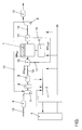
- the single figure shows a simplified representation of a simulation model for simulation of the gas flow in a motor vehicle or a corresponding internal combustion engine according to the present invention.
- an internal combustion engine 1 with four combustion chambers or cylinders is shown.
- the internal combustion engine 1 is coupled to an exhaust gas turbocharger (ATL), which is a turbine 2 and a compressor 7, the turbine 2 and the compressor 7 on one common shaft 14, the so-called turbocharger shaft, are attached.
- ATL exhaust gas turbocharger
- the turbine 2 uses the energy contained in the exhaust gas of the internal combustion engine 1 to drive the compressor 7, which sucks in fresh air via an intake tract and pre-compressed air into the individual Combustion chambers of the internal combustion engine 1 presses.
- the fresh air mass flow drawn in is by an air mass meter 6 arranged relatively far forward in the intake tract measured and thus recorded in the operation of the internal combustion engine 1 or the motor vehicle.
- the exhaust gas turbocharger formed by the turbine 2, the compressor 7 and the turbocharger shaft 14 is only fluidly with the internal combustion engine through the air and exhaust gas mass flow 1 coupled.
- the fresh air drawn in and precompressed by the compressor 7 is supplied to a so-called replacement volume (ERS) 9 via a charge air cooler (LLK) 8, which reduces the exhaust gas temperature and thus the NO x emission and the fuel consumption.
- ERS replacement volume
- LLK charge air cooler
- An intake manifold (ELS) 10 is connected upstream of the individual combustion chambers of the internal combustion engine 1.
- the exhaust gas generated in the combustion chambers of the internal combustion engine 1 is collected by an exhaust gas collector (ASA) 11 and fed to the turbine 2.
- ASA exhaust gas collector
- the turbine 2 is followed in the exhaust gas flow direction by the exhaust system (APU) 12 of the motor vehicle, which breaks down the pollutant components of the exhaust gases generated during operation of the internal combustion engine 1 and discharges the remaining exhaust gases as quietly as possible.
- Part of the exhaust gas generated in the combustion chambers of the internal combustion engine 1 is returned from the exhaust gas collector 11 via an exhaust gas recirculation (EGR) 16 with an exhaust gas recirculation valve 17 to the intake manifold 10, where the recirculated exhaust gas is mixed with the fresh air drawn in and the fresh air / Exhaust gas mixture is supplied to the corresponding cylinder of the internal combustion engine 1.
- EGR exhaust gas recirculation
- a control device 4 which is part of a corresponding one Motor management system of the motor vehicle is. Different from the control unit 4 Sizes or operating parameters of the motor system shown monitor which with the help of appropriate sensors and via an interface 3 to the control unit 4 are supplied. In particular, this can be that of the air mass meter 6 measured fresh air mass flow, the engine speed, the density of the fresh air / exhaust gas mixture in the connection between the inlet header 10 and the Combustion engine 1, the so-called intake manifold, etc. act. Which in this way by Measured variables recorded in control device 4 are evaluated in order to make them dependent on them Generate control signals for the engine management system.
- Control signals for example, the duty cycle of the arranged in the exhaust gas recirculation Exhaust gas recirculation valve 17, the guide vane adjustment 15 of the turbine 2 or the time of injection and the amount of fuel injected into the individual combustion chambers of the internal combustion engine 1 control air fuel mixture etc. injected via an injection system 5.
- the reference numerals 13 in FIG. 1 are arranged in corresponding air or gas paths Valves.
- a characteristic diagram or a characteristic curve of the cylinder mass flow dm cyl ie the mass flow of the individual cylinders of the internal combustion engine via the inlet manifold 10, which has the mixing point for the fresh air and the recirculated exhaust gas, is determined by means of test bench measurements Intake pipe designated connecting line supplied fresh air / exhaust gas mixture, determined depending on various operating parameters of the internal combustion engine.
- the cylinder mass flow dm cyl is known to depend , among other things, on the intake manifold pressure, the intake manifold temperature , the density in the intake manifold and the engine speed.
- p 0 , p 1 , p 2 denote different measured values or operating parameters which are included in the model, while a 0 , a 1 , a 2 denote coefficients which describe the model.
- the physical relationship between the individual operating parameters and coefficients does not necessarily have to be known as an equation. It is also sufficient to have a characteristic curve or a characteristic diagram or characteristic space that can be mapped into a polynomial.
- the fresh air mass flow dm HFM is continuously measured by the air mass meter 6 and supplied to the control unit 4.
- the previously described characteristic of the cylinder mass flow dm cyl is stored in the control device 4 , so that this characteristic is known to the control device 4.
- the control unit adapts this characteristic during operation in such a way that the above equation is fulfilled at each operating point of the internal combustion engine 1 with known values of the exhaust gas recirculation mass flow dm EGR .
- the comparison of the characteristic curve of the cylinder mass flow can also take place with the exhaust gas recirculation valve 17 open, since, for example, methods are also known for determining the instantaneous value of the exhaust gas recirculation mass flow dm EGR from certain measured operating parameters of the internal combustion engine 1.
- What is important for the previously described comparison of the characteristic curve of the cylinder mass flow dm cyl is, in principle, only that information which is as reliable or estimated as possible about the value of the exhaust gas recirculation mass flow dm EGR valid at the respective operating point is independent of the previously described, possibly faulty sensors, in particular independently of the air mass meter 6, are known. At least the degree of unreliability of the information used should be known.
- the characteristic curve of the cylinder mass flow dm cyl can be adjusted , for example, by adapting the coefficients a 0 , a 1 , a 2 ... of the model according to equation (3) during operation.
- the above equation (1) uses this adjusted or adapted characteristic curve for all operating conditions, in particular for relatively small exhaust gas recirculation rates, to provide the mass flow corrected except for a percentage error of the hot film air mass meter 6 that may be present the inlet valve.
- An additional error due to the difference formation according to equation (1) no longer occurs, so that the exhaust gas recirculation mass flow dm EGR only has the percentage error of the hot film air mass meter 6 at each operating point.
- Errors in a charge air temperature sensor , a charge pressure sensor or manufacturing tolerances of the charge air path which, as described, can conventionally lead to errors in the determination of the cylinder mass flow dm cyl , are automatically eliminated or calibrated out by the control device 4 during operation of the motor vehicle by the control device 4 and do not go into either certain mass flows, as long as the display of the sensors involved remains clear.
- the adjustment method described above is also particularly advantageous with regard to the determination of the exhaust gas recirculation rate r EGR according to equation (2). Since the characteristic curve of the cylinder mass flow dm zyl is just adjusted as described so that the percentage errors of the cylinder mass flow dm zyl and the fresh air mass flow dm HFM are the same, the exhaust gas recirculation mass flow dm EGR that can be derived from this in accordance with equation (1) also has the same percentage error. When forming the quotient according to equation (2) for determining the exhaust gas recirculation rate r EGR , this percentage error is reduced and is therefore eliminated, ie the exhaust gas recirculation rate r AGR can in principle be determined without errors.
Landscapes
- Engineering & Computer Science (AREA)
- Chemical & Material Sciences (AREA)
- Combustion & Propulsion (AREA)
- Mechanical Engineering (AREA)
- General Engineering & Computer Science (AREA)
- Exhaust-Gas Circulating Devices (AREA)
- Output Control And Ontrol Of Special Type Engine (AREA)
Applications Claiming Priority (2)
| Application Number | Priority Date | Filing Date | Title |
|---|---|---|---|
| DE10260322A DE10260322A1 (de) | 2002-12-20 | 2002-12-20 | Verfahren und Vorrichtung zur Bestimmung des Abgasrückführmassenstroms eines Verbrennungsmotors |
| DE10260322 | 2002-12-20 |
Publications (3)
| Publication Number | Publication Date |
|---|---|
| EP1431547A2 true EP1431547A2 (fr) | 2004-06-23 |
| EP1431547A3 EP1431547A3 (fr) | 2006-01-18 |
| EP1431547B1 EP1431547B1 (fr) | 2009-10-07 |
Family
ID=32336552
Family Applications (1)
| Application Number | Title | Priority Date | Filing Date |
|---|---|---|---|
| EP03028160A Expired - Lifetime EP1431547B1 (fr) | 2002-12-20 | 2003-12-08 | Procédé et dispositif pour déterminer le débit du gaz d'échappement recirculé dans un moteur à combustion interne |
Country Status (4)
| Country | Link |
|---|---|
| US (1) | US6871134B2 (fr) |
| EP (1) | EP1431547B1 (fr) |
| AT (1) | ATE445093T1 (fr) |
| DE (2) | DE10260322A1 (fr) |
Families Citing this family (10)
| Publication number | Priority date | Publication date | Assignee | Title |
|---|---|---|---|---|
| DE10144337B4 (de) * | 2001-09-10 | 2007-04-19 | Siemens Ag | Adaptives Regelverfahren |
| EP1715163A1 (fr) * | 2001-11-28 | 2006-10-25 | Volkswagen Aktiengesellschaft | Procédé pour déterminer la composition d'un mélange gazeux dans une chambre de combustion d'un moteur à combustion interne comprenant une conduite de recyclage des gaz d'échappemment |
| US7107143B2 (en) * | 2004-07-21 | 2006-09-12 | General Motors Corporation | Estimation of oxygen concentration in the intake manifold of an unthrottled lean burn engine |
| DE102004047099B3 (de) * | 2004-09-29 | 2006-03-16 | Bayerische Motoren Werke Ag | Verfahren zur Bestimmung der Frischluftmasse eines Verbrennungsmotors |
| US7291934B2 (en) * | 2005-08-30 | 2007-11-06 | Caterpillar Inc. | Machine with an electrical system |
| US7493896B2 (en) * | 2006-12-27 | 2009-02-24 | Gm Global Technology Operations, Inc. | Exhaust gas recirculation estimation system |
| DE102010027976A1 (de) * | 2010-04-20 | 2011-10-20 | Robert Bosch Gmbh | Verfahren zum Betreiben einer Brennkraftmaschine mit einem Zuführstrang zur Zuführung eines Luftgemischs sowie mit einem Abgasstrang |
| US8616186B2 (en) * | 2011-07-05 | 2013-12-31 | Ford Global Technologies, Llc | Exhaust gas recirculation (EGR) system |
| KR20160050924A (ko) * | 2014-10-31 | 2016-05-11 | 현대자동차주식회사 | 수랭식 인터쿨러를 구비한 차량의 워터 펌프 제어 시스템 및 방법 |
| JP6707038B2 (ja) * | 2017-01-23 | 2020-06-10 | 日立オートモティブシステムズ株式会社 | 内燃機関の制御装置 |
Citations (3)
| Publication number | Priority date | Publication date | Assignee | Title |
|---|---|---|---|---|
| DE19920498A1 (de) * | 1998-05-09 | 1999-11-11 | Bosch Gmbh Robert | Verfahren und Vorrichtung zur Steuerung einer Brennkraftmaschine |
| DE19950146A1 (de) * | 1998-10-16 | 2000-04-27 | Cummins Engine Co Inc | On-Line-Selbstkalibrierung von Luftmassensensoren in Verbrennungsmotoren |
| WO2004003364A1 (fr) * | 2002-06-29 | 2004-01-08 | Daimlerchrysler Ag | Procede de determination de la quantite de gaz d'echappement recycles |
Family Cites Families (5)
| Publication number | Priority date | Publication date | Assignee | Title |
|---|---|---|---|---|
| JPH06330821A (ja) * | 1993-05-25 | 1994-11-29 | Fuji Heavy Ind Ltd | エンジンの排気ガス還流率制御方法 |
| DE4422184C2 (de) * | 1994-06-24 | 2003-01-30 | Bayerische Motoren Werke Ag | Steuergerät für Kraftfahrzeuge mit einer Recheneinheit zur Berechnung der in einen Zylinder der Brennkraftmaschine strömenden Luftmasse |
| DE19615545C1 (de) * | 1996-04-19 | 1997-06-12 | Daimler Benz Ag | Einrichtung zur Dieselmotorbetriebsregelung mit Abgasrückführung und Ansaugluftdrosselung |
| DE19959854A1 (de) * | 1999-12-10 | 2001-06-13 | Heraeus Electro Nite Int | Verfahren zur Abgasrückführung in einem Luftansaugbereich von Fahrzeug-Brennkraftmaschinen sowie Vorrichtung |
| FR2829185B1 (fr) * | 2001-09-04 | 2006-01-13 | Renault | Procede et dispositif de commande d'une soupape de reglage d'un flux de gaz d'echappement recircules dans le collecteur d'admission d'un moteur a combustion interne |
-
2002
- 2002-12-20 DE DE10260322A patent/DE10260322A1/de not_active Withdrawn
-
2003
- 2003-12-08 AT AT03028160T patent/ATE445093T1/de not_active IP Right Cessation
- 2003-12-08 DE DE50311996T patent/DE50311996D1/de not_active Expired - Lifetime
- 2003-12-08 EP EP03028160A patent/EP1431547B1/fr not_active Expired - Lifetime
- 2003-12-12 US US10/735,438 patent/US6871134B2/en not_active Expired - Fee Related
Patent Citations (3)
| Publication number | Priority date | Publication date | Assignee | Title |
|---|---|---|---|---|
| DE19920498A1 (de) * | 1998-05-09 | 1999-11-11 | Bosch Gmbh Robert | Verfahren und Vorrichtung zur Steuerung einer Brennkraftmaschine |
| DE19950146A1 (de) * | 1998-10-16 | 2000-04-27 | Cummins Engine Co Inc | On-Line-Selbstkalibrierung von Luftmassensensoren in Verbrennungsmotoren |
| WO2004003364A1 (fr) * | 2002-06-29 | 2004-01-08 | Daimlerchrysler Ag | Procede de determination de la quantite de gaz d'echappement recycles |
Non-Patent Citations (1)
| Title |
|---|
| PATENT ABSTRACTS OF JAPAN Bd. 1995, Nr. 02, 31. März 1995 (1995-03-31) -& JP 06 330821 A (FUJI HEAVY IND LTD), 29. November 1994 (1994-11-29) * |
Also Published As
| Publication number | Publication date |
|---|---|
| US20040148087A1 (en) | 2004-07-29 |
| ATE445093T1 (de) | 2009-10-15 |
| DE50311996D1 (de) | 2009-11-19 |
| DE10260322A1 (de) | 2004-07-08 |
| EP1431547B1 (fr) | 2009-10-07 |
| EP1431547A3 (fr) | 2006-01-18 |
| US6871134B2 (en) | 2005-03-22 |
Similar Documents
| Publication | Publication Date | Title |
|---|---|---|
| DE602004012986T2 (de) | Verfahren und Einrichtung zur Bestimmung der Ansaugluftmenge einer Brennkraftmaschine basierend auf der Messung der Sauerstoffkonzentration in einem der Brennkraftmaschine zugeführten Gasgemisch | |
| DE60320199T2 (de) | Vorrichtung zur Schätzung der Abgasrückführrate in einer Brennkraftmaschine | |
| DE19950146C2 (de) | On-Line-Selbstkalibrierung von Luftmassensensoren in Verbrennungsmotoren | |
| DE102008025452B4 (de) | Überwachung der Leistung einer Lambdasonde | |
| EP1701025B1 (fr) | Procédé pour déterminer la composition d'un mélange gazeux dans une chambre de combustion d'un moteur à combustion interne comprenant une conduite de recyclage des gaz d'échappement | |
| DE102005013977B4 (de) | Abgasrückführsystem für ein Kraftfahrzeug und Verfahren zum Einstellen der Abgasrückführrate in einem Gasrückführsystem | |
| DE19740916A1 (de) | Verfahren zum Betreiben einer Brennkraftmaschine | |
| DE102011003095A1 (de) | Verfahren zur Ermittlung der SauerstoffkonzentrationO2 in einer Gasströmung und Sauerstoffsensor zur Durchführung des Verfahrens | |
| DE112010000700T5 (de) | Abgasrückführungssystem und Verfahren zum Betreiben eines solchen Systems | |
| DE102004040924B4 (de) | Verfahren und Vorrichtung zur Überwachung von Drucksensoren im Abgasstrang | |
| DE112007000409B4 (de) | Verfahren zum Steuern von Turbinenauslasstemperaturen in einem Dieselmotor | |
| DE69826067T2 (de) | Brennkraftmaschine | |
| EP1091106B1 (fr) | Méthode d'évaluation de la contre-pression des gaz d'échappement au niveau de la turbine | |
| DE19912317A1 (de) | Verfahren zur Regelung des Anteils der einer Brennkraftmaschine rückgeführten Abgasmenge | |
| EP1431547B1 (fr) | Procédé et dispositif pour déterminer le débit du gaz d'échappement recirculé dans un moteur à combustion interne | |
| DE102004026006A1 (de) | Steuergerät und Steuerverfahren für eine Brennkraftmaschine | |
| DE19527774C2 (de) | Katalysatorverschlechterungs-Bestimmungsvorrichtung für einen Verbrennungsmotor | |
| DE102004019315A1 (de) | Verfahren zur Bestimmung von Zustandsgrößen eines Gasgemisches in einer einem Verbrennungsmotor zugeordneten Luftstecke und entsprechend ausgestaltete Motostreuerung | |
| DE102008042819B4 (de) | Verfahren und Vorrichtung zum Bestimmen einer gesamten Zylinderfüllung und/oder der aktuellen Restgasrate bei einem Verbrennungsmotor mit Abgasrückführung | |
| DE10102914C1 (de) | Verfahren zum Ermitteln eines Schätzwertes eines Massenstroms in den Ansaugtrakt einer Brennkraftmaschine | |
| DE102009055120A1 (de) | Verfahren und Vorrichtung zur Durchführung einer Onboard-Diagnose | |
| EP1081361A2 (fr) | Contrôle du fonctionnement d'un système de régulation de masse d'air | |
| DE10111775B4 (de) | Verfahren und Vorrichtung zur Bestimmung der Gasaustrittstemperatur der Turbine eines Abgasturboladers eines Kraftfahrzeugs | |
| DE102012004556B4 (de) | Verfahren und Vorrichtung zum Bestimmen eines Verbrennungsluftmassenstroms | |
| DE10162970B4 (de) | Verfahren und Vorrichtung zur Bestimmung des Abgasrückführmassenstroms eines Verbrennungsmotors |
Legal Events
| Date | Code | Title | Description |
|---|---|---|---|
| PUAI | Public reference made under article 153(3) epc to a published international application that has entered the european phase |
Free format text: ORIGINAL CODE: 0009012 |
|
| AK | Designated contracting states |
Kind code of ref document: A2 Designated state(s): AT BE BG CH CY CZ DE DK EE ES FI FR GB GR HU IE IT LI LU MC NL PT RO SE SI SK TR |
|
| AX | Request for extension of the european patent |
Extension state: AL LT LV MK |
|
| PUAL | Search report despatched |
Free format text: ORIGINAL CODE: 0009013 |
|
| AK | Designated contracting states |
Kind code of ref document: A3 Designated state(s): AT BE BG CH CY CZ DE DK EE ES FI FR GB GR HU IE IT LI LU MC NL PT RO SE SI SK TR |
|
| AX | Request for extension of the european patent |
Extension state: AL LT LV MK |
|
| 17P | Request for examination filed |
Effective date: 20060718 |
|
| AKX | Designation fees paid |
Designated state(s): AT BE BG CH CY CZ DE DK EE ES FI FR GB GR HU IE IT LI LU MC NL PT RO SE SI SK TR |
|
| 17Q | First examination report despatched |
Effective date: 20060918 |
|
| GRAP | Despatch of communication of intention to grant a patent |
Free format text: ORIGINAL CODE: EPIDOSNIGR1 |
|
| GRAS | Grant fee paid |
Free format text: ORIGINAL CODE: EPIDOSNIGR3 |
|
| GRAA | (expected) grant |
Free format text: ORIGINAL CODE: 0009210 |
|
| AK | Designated contracting states |
Kind code of ref document: B1 Designated state(s): AT BE BG CH CY CZ DE DK EE ES FI FR GB GR HU IE IT LI LU MC NL PT RO SE SI SK TR |
|
| REG | Reference to a national code |
Ref country code: GB Ref legal event code: FG4D Free format text: NOT ENGLISH |
|
| REG | Reference to a national code |
Ref country code: CH Ref legal event code: EP |
|
| REG | Reference to a national code |
Ref country code: IE Ref legal event code: FG4D |
|
| REF | Corresponds to: |
Ref document number: 50311996 Country of ref document: DE Date of ref document: 20091119 Kind code of ref document: P |
|
| PG25 | Lapsed in a contracting state [announced via postgrant information from national office to epo] |
Ref country code: SI Free format text: LAPSE BECAUSE OF FAILURE TO SUBMIT A TRANSLATION OF THE DESCRIPTION OR TO PAY THE FEE WITHIN THE PRESCRIBED TIME-LIMIT Effective date: 20091007 |
|
| NLV1 | Nl: lapsed or annulled due to failure to fulfill the requirements of art. 29p and 29m of the patents act | ||
| PG25 | Lapsed in a contracting state [announced via postgrant information from national office to epo] |
Ref country code: ES Free format text: LAPSE BECAUSE OF FAILURE TO SUBMIT A TRANSLATION OF THE DESCRIPTION OR TO PAY THE FEE WITHIN THE PRESCRIBED TIME-LIMIT Effective date: 20100118 Ref country code: SE Free format text: LAPSE BECAUSE OF FAILURE TO SUBMIT A TRANSLATION OF THE DESCRIPTION OR TO PAY THE FEE WITHIN THE PRESCRIBED TIME-LIMIT Effective date: 20091007 Ref country code: PT Free format text: LAPSE BECAUSE OF FAILURE TO SUBMIT A TRANSLATION OF THE DESCRIPTION OR TO PAY THE FEE WITHIN THE PRESCRIBED TIME-LIMIT Effective date: 20100208 Ref country code: FI Free format text: LAPSE BECAUSE OF FAILURE TO SUBMIT A TRANSLATION OF THE DESCRIPTION OR TO PAY THE FEE WITHIN THE PRESCRIBED TIME-LIMIT Effective date: 20091007 |
|
| REG | Reference to a national code |
Ref country code: IE Ref legal event code: FD4D |
|
| BERE | Be: lapsed |
Owner name: VOLKSWAGEN AG Effective date: 20091231 |
|
| PG25 | Lapsed in a contracting state [announced via postgrant information from national office to epo] |
Ref country code: MC Free format text: LAPSE BECAUSE OF NON-PAYMENT OF DUE FEES Effective date: 20100701 Ref country code: IE Free format text: LAPSE BECAUSE OF FAILURE TO SUBMIT A TRANSLATION OF THE DESCRIPTION OR TO PAY THE FEE WITHIN THE PRESCRIBED TIME-LIMIT Effective date: 20091007 Ref country code: BG Free format text: LAPSE BECAUSE OF FAILURE TO SUBMIT A TRANSLATION OF THE DESCRIPTION OR TO PAY THE FEE WITHIN THE PRESCRIBED TIME-LIMIT Effective date: 20100107 Ref country code: EE Free format text: LAPSE BECAUSE OF FAILURE TO SUBMIT A TRANSLATION OF THE DESCRIPTION OR TO PAY THE FEE WITHIN THE PRESCRIBED TIME-LIMIT Effective date: 20091007 Ref country code: DK Free format text: LAPSE BECAUSE OF FAILURE TO SUBMIT A TRANSLATION OF THE DESCRIPTION OR TO PAY THE FEE WITHIN THE PRESCRIBED TIME-LIMIT Effective date: 20091007 Ref country code: RO Free format text: LAPSE BECAUSE OF FAILURE TO SUBMIT A TRANSLATION OF THE DESCRIPTION OR TO PAY THE FEE WITHIN THE PRESCRIBED TIME-LIMIT Effective date: 20091007 Ref country code: NL Free format text: LAPSE BECAUSE OF FAILURE TO SUBMIT A TRANSLATION OF THE DESCRIPTION OR TO PAY THE FEE WITHIN THE PRESCRIBED TIME-LIMIT Effective date: 20091007 |
|
| REG | Reference to a national code |
Ref country code: CH Ref legal event code: PL |
|
| PLBE | No opposition filed within time limit |
Free format text: ORIGINAL CODE: 0009261 |
|
| STAA | Information on the status of an ep patent application or granted ep patent |
Free format text: STATUS: NO OPPOSITION FILED WITHIN TIME LIMIT |
|
| PG25 | Lapsed in a contracting state [announced via postgrant information from national office to epo] |
Ref country code: SK Free format text: LAPSE BECAUSE OF FAILURE TO SUBMIT A TRANSLATION OF THE DESCRIPTION OR TO PAY THE FEE WITHIN THE PRESCRIBED TIME-LIMIT Effective date: 20091007 Ref country code: CZ Free format text: LAPSE BECAUSE OF FAILURE TO SUBMIT A TRANSLATION OF THE DESCRIPTION OR TO PAY THE FEE WITHIN THE PRESCRIBED TIME-LIMIT Effective date: 20091007 |
|
| 26N | No opposition filed |
Effective date: 20100708 |
|
| REG | Reference to a national code |
Ref country code: FR Ref legal event code: ST Effective date: 20100831 |
|
| GBPC | Gb: european patent ceased through non-payment of renewal fee |
Effective date: 20100107 |
|
| PG25 | Lapsed in a contracting state [announced via postgrant information from national office to epo] |
Ref country code: LI Free format text: LAPSE BECAUSE OF NON-PAYMENT OF DUE FEES Effective date: 20091231 Ref country code: FR Free format text: LAPSE BECAUSE OF NON-PAYMENT OF DUE FEES Effective date: 20091231 Ref country code: GR Free format text: LAPSE BECAUSE OF FAILURE TO SUBMIT A TRANSLATION OF THE DESCRIPTION OR TO PAY THE FEE WITHIN THE PRESCRIBED TIME-LIMIT Effective date: 20100108 Ref country code: BE Free format text: LAPSE BECAUSE OF NON-PAYMENT OF DUE FEES Effective date: 20091231 Ref country code: CH Free format text: LAPSE BECAUSE OF NON-PAYMENT OF DUE FEES Effective date: 20091231 |
|
| PG25 | Lapsed in a contracting state [announced via postgrant information from national office to epo] |
Ref country code: GB Free format text: LAPSE BECAUSE OF NON-PAYMENT OF DUE FEES Effective date: 20100107 |
|
| PG25 | Lapsed in a contracting state [announced via postgrant information from national office to epo] |
Ref country code: IT Free format text: LAPSE BECAUSE OF FAILURE TO SUBMIT A TRANSLATION OF THE DESCRIPTION OR TO PAY THE FEE WITHIN THE PRESCRIBED TIME-LIMIT Effective date: 20091007 |
|
| PG25 | Lapsed in a contracting state [announced via postgrant information from national office to epo] |
Ref country code: LU Free format text: LAPSE BECAUSE OF NON-PAYMENT OF DUE FEES Effective date: 20091208 |
|
| PG25 | Lapsed in a contracting state [announced via postgrant information from national office to epo] |
Ref country code: AT Free format text: LAPSE BECAUSE OF NON-PAYMENT OF DUE FEES Effective date: 20091208 |
|
| PG25 | Lapsed in a contracting state [announced via postgrant information from national office to epo] |
Ref country code: HU Free format text: LAPSE BECAUSE OF FAILURE TO SUBMIT A TRANSLATION OF THE DESCRIPTION OR TO PAY THE FEE WITHIN THE PRESCRIBED TIME-LIMIT Effective date: 20100408 |
|
| PG25 | Lapsed in a contracting state [announced via postgrant information from national office to epo] |
Ref country code: TR Free format text: LAPSE BECAUSE OF FAILURE TO SUBMIT A TRANSLATION OF THE DESCRIPTION OR TO PAY THE FEE WITHIN THE PRESCRIBED TIME-LIMIT Effective date: 20091007 |
|
| PG25 | Lapsed in a contracting state [announced via postgrant information from national office to epo] |
Ref country code: CY Free format text: LAPSE BECAUSE OF FAILURE TO SUBMIT A TRANSLATION OF THE DESCRIPTION OR TO PAY THE FEE WITHIN THE PRESCRIBED TIME-LIMIT Effective date: 20091007 |
|
| PGFP | Annual fee paid to national office [announced via postgrant information from national office to epo] |
Ref country code: DE Payment date: 20181231 Year of fee payment: 16 |
|
| REG | Reference to a national code |
Ref country code: DE Ref legal event code: R119 Ref document number: 50311996 Country of ref document: DE |
|
| PG25 | Lapsed in a contracting state [announced via postgrant information from national office to epo] |
Ref country code: DE Free format text: LAPSE BECAUSE OF NON-PAYMENT OF DUE FEES Effective date: 20200701 |