EP1431547A2 - Method and device for calculating the exhaust gas recirculation amount in an internal combustion engine - Google Patents
Method and device for calculating the exhaust gas recirculation amount in an internal combustion engine Download PDFInfo
- Publication number
- EP1431547A2 EP1431547A2 EP03028160A EP03028160A EP1431547A2 EP 1431547 A2 EP1431547 A2 EP 1431547A2 EP 03028160 A EP03028160 A EP 03028160A EP 03028160 A EP03028160 A EP 03028160A EP 1431547 A2 EP1431547 A2 EP 1431547A2
- Authority
- EP
- European Patent Office
- Prior art keywords
- mass flow
- exhaust gas
- gas recirculation
- combustion engine
- internal combustion
- Prior art date
- Legal status (The legal status is an assumption and is not a legal conclusion. Google has not performed a legal analysis and makes no representation as to the accuracy of the status listed.)
- Granted
Links
Images
Classifications
-
- F—MECHANICAL ENGINEERING; LIGHTING; HEATING; WEAPONS; BLASTING
- F02—COMBUSTION ENGINES; HOT-GAS OR COMBUSTION-PRODUCT ENGINE PLANTS
- F02D—CONTROLLING COMBUSTION ENGINES
- F02D21/00—Controlling engines characterised by their being supplied with non-airborne oxygen or other non-fuel gas
- F02D21/06—Controlling engines characterised by their being supplied with non-airborne oxygen or other non-fuel gas peculiar to engines having other non-fuel gas added to combustion air
- F02D21/08—Controlling engines characterised by their being supplied with non-airborne oxygen or other non-fuel gas peculiar to engines having other non-fuel gas added to combustion air the other gas being the exhaust gas of engine
-
- F—MECHANICAL ENGINEERING; LIGHTING; HEATING; WEAPONS; BLASTING
- F02—COMBUSTION ENGINES; HOT-GAS OR COMBUSTION-PRODUCT ENGINE PLANTS
- F02D—CONTROLLING COMBUSTION ENGINES
- F02D41/00—Electrical control of supply of combustible mixture or its constituents
- F02D41/0025—Controlling engines characterised by use of non-liquid fuels, pluralities of fuels, or non-fuel substances added to the combustible mixtures
- F02D41/0047—Controlling exhaust gas recirculation [EGR]
- F02D41/0065—Specific aspects of external EGR control
- F02D41/0072—Estimating, calculating or determining the EGR rate, amount or flow
-
- F—MECHANICAL ENGINEERING; LIGHTING; HEATING; WEAPONS; BLASTING
- F02—COMBUSTION ENGINES; HOT-GAS OR COMBUSTION-PRODUCT ENGINE PLANTS
- F02D—CONTROLLING COMBUSTION ENGINES
- F02D41/00—Electrical control of supply of combustible mixture or its constituents
- F02D41/24—Electrical control of supply of combustible mixture or its constituents characterised by the use of digital means
- F02D41/2406—Electrical control of supply of combustible mixture or its constituents characterised by the use of digital means using essentially read only memories
- F02D41/2425—Particular ways of programming the data
- F02D41/2429—Methods of calibrating or learning
- F02D41/2451—Methods of calibrating or learning characterised by what is learned or calibrated
-
- F—MECHANICAL ENGINEERING; LIGHTING; HEATING; WEAPONS; BLASTING
- F02—COMBUSTION ENGINES; HOT-GAS OR COMBUSTION-PRODUCT ENGINE PLANTS
- F02B—INTERNAL-COMBUSTION PISTON ENGINES; COMBUSTION ENGINES IN GENERAL
- F02B29/00—Engines characterised by provision for charging or scavenging not provided for in groups F02B25/00, F02B27/00 or F02B33/00 - F02B39/00; Details thereof
- F02B29/04—Cooling of air intake supply
- F02B29/0406—Layout of the intake air cooling or coolant circuit
-
- F—MECHANICAL ENGINEERING; LIGHTING; HEATING; WEAPONS; BLASTING
- F02—COMBUSTION ENGINES; HOT-GAS OR COMBUSTION-PRODUCT ENGINE PLANTS
- F02D—CONTROLLING COMBUSTION ENGINES
- F02D2200/00—Input parameters for engine control
- F02D2200/02—Input parameters for engine control the parameters being related to the engine
- F02D2200/04—Engine intake system parameters
- F02D2200/0406—Intake manifold pressure
-
- F—MECHANICAL ENGINEERING; LIGHTING; HEATING; WEAPONS; BLASTING
- F02—COMBUSTION ENGINES; HOT-GAS OR COMBUSTION-PRODUCT ENGINE PLANTS
- F02D—CONTROLLING COMBUSTION ENGINES
- F02D41/00—Electrical control of supply of combustible mixture or its constituents
- F02D41/24—Electrical control of supply of combustible mixture or its constituents characterised by the use of digital means
- F02D41/2406—Electrical control of supply of combustible mixture or its constituents characterised by the use of digital means using essentially read only memories
- F02D41/2425—Particular ways of programming the data
- F02D41/2429—Methods of calibrating or learning
- F02D41/2441—Methods of calibrating or learning characterised by the learning conditions
-
- F—MECHANICAL ENGINEERING; LIGHTING; HEATING; WEAPONS; BLASTING
- F02—COMBUSTION ENGINES; HOT-GAS OR COMBUSTION-PRODUCT ENGINE PLANTS
- F02M—SUPPLYING COMBUSTION ENGINES IN GENERAL WITH COMBUSTIBLE MIXTURES OR CONSTITUENTS THEREOF
- F02M26/00—Engine-pertinent apparatus for adding exhaust gases to combustion-air, main fuel or fuel-air mixture, e.g. by exhaust gas recirculation [EGR] systems
- F02M26/02—EGR systems specially adapted for supercharged engines
- F02M26/04—EGR systems specially adapted for supercharged engines with a single turbocharger
- F02M26/05—High pressure loops, i.e. wherein recirculated exhaust gas is taken out from the exhaust system upstream of the turbine and reintroduced into the intake system downstream of the compressor
-
- Y—GENERAL TAGGING OF NEW TECHNOLOGICAL DEVELOPMENTS; GENERAL TAGGING OF CROSS-SECTIONAL TECHNOLOGIES SPANNING OVER SEVERAL SECTIONS OF THE IPC; TECHNICAL SUBJECTS COVERED BY FORMER USPC CROSS-REFERENCE ART COLLECTIONS [XRACs] AND DIGESTS
- Y02—TECHNOLOGIES OR APPLICATIONS FOR MITIGATION OR ADAPTATION AGAINST CLIMATE CHANGE
- Y02T—CLIMATE CHANGE MITIGATION TECHNOLOGIES RELATED TO TRANSPORTATION
- Y02T10/00—Road transport of goods or passengers
- Y02T10/10—Internal combustion engine [ICE] based vehicles
- Y02T10/40—Engine management systems
Definitions
- the present invention relates to a method and an apparatus for determining the Exhaust gas recirculation mass flow of an internal combustion engine, for example a diesel engine.
- the present invention relates to such a method and such Device, with the help of the information thus obtained about the exhaust gas recirculation mass flow the exhaust gas recirculation rate can be determined correctly.
- an operating parameter is the exhaust gas recirculation mass flow in an internal combustion engine with exhaust gas recirculation, d. H. the mass flow of that emitted by the internal combustion engine Exhaust gas, which is fed to a mixing point via an exhaust gas recirculation line, where the exhaust gas is mixed with fresh air sucked in to the resulting fresh air / exhaust gas mixture to feed the combustion chambers of the internal combustion engine.
- Exhaust gas recirculation rate i.e. the quotient from the fresh air mass flow drawn in and the exhaust gas recirculation mass flow is important for compliance with exhaust gas regulations.
- the exhaust gas recirculation mass flow can only be measured with expensive or short-lived sensors.
- the determination of the exhaust gas recirculation rate is also strong with the conventional procedure faulty.
- test results are first used to determine the total or cylinder mass flow dm cyl drawn into the respective cylinder or combustion chamber of the internal combustion engine from various operating parameters .
- the operating parameters include the pressure and the temperature in the connection (the so-called intake manifold) between the aforementioned mixing point and the cylinder, as well as the injection quantity of the air / fuel mixture and the engine speed, with the test results measuring the cylinder mass flow, which in principle corresponds to the sum of the fresh air mass flow dm HFM and the exhaust gas recirculation mass flow dm EGR , depending on these operating parameters, in the form of a map, that is to say it is known at which operating parameter values which cylinder mass flow occurs.
- the fresh air mass flow drawn in is measured with the aid of an air mass sensor, for example a hot film air mass sensor, in the intake tract.
- the method described above is sensitive to tolerances of the measurement signals and manufacturing-related tolerances of the inlet area.
- a difference in the absolute errors of the two determined mass flows dm HFM and dm cyl goes directly into the exhaust gas recirculation mass flow dm EGR , which is determined as a relatively small difference between two relatively large variables and therefore with high sensitivity, the error in the detection of the cylinder mass flow, for example dm cyl essentially consists of manufacturing tolerances of the charge air path and measurement errors of the charge pressure and charge temperature sensors, while the error in the detection of the fresh air mass flow dm HFM is essentially due to measurement errors of the air mass sensor.
- the present invention is therefore based on the object of a method and a corresponding one designed device for determining the exhaust gas recirculation mass flow To provide internal combustion engine, with which the most accurate determination of the Exhaust gas recirculation mass flow and in particular the most accurate determination of the Exhaust gas recirculation rate is possible.
- the exhaust gas recirculation mass flow is determined as in the previous one described conventional procedure of fresh air mass flow measured to depending on this, evaluating the cylinder mass flow, which is the exhaust gas recirculation mass flow and comprises the fresh air mass flow, the exhaust gas recirculation mass flow in to determine ongoing operation of the internal combustion engine.
- this is ongoing Operation of the cylinder mass flow depending on various operating parameters characteristic curve of the internal combustion engine, which e.g. before commissioning the Internal combustion engine has been determined by test bench measurements, so for the different Operating points of the internal combustion engine measured and thus known Fresh air mass flow adjusted, i.e.
- the exhaust gas recirculation mass flow Since the characteristic curve of the cylinder mass flow is adjusted in such a way that the percentage Error of the cylinder mass flow and the fresh air mass flow is the same the exhaust gas recirculation mass flow also has the same percentage error. In the This percentage error becomes the quotient for determining the exhaust gas recirculation rate shortened and thus eliminated, so that the exhaust gas recirculation rate according to the invention Principle can be determined without errors.
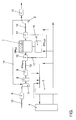
- the single figure shows a simplified representation of a simulation model for simulation of the gas flow in a motor vehicle or a corresponding internal combustion engine according to the present invention.
- an internal combustion engine 1 with four combustion chambers or cylinders is shown.
- the internal combustion engine 1 is coupled to an exhaust gas turbocharger (ATL), which is a turbine 2 and a compressor 7, the turbine 2 and the compressor 7 on one common shaft 14, the so-called turbocharger shaft, are attached.
- ATL exhaust gas turbocharger
- the turbine 2 uses the energy contained in the exhaust gas of the internal combustion engine 1 to drive the compressor 7, which sucks in fresh air via an intake tract and pre-compressed air into the individual Combustion chambers of the internal combustion engine 1 presses.
- the fresh air mass flow drawn in is by an air mass meter 6 arranged relatively far forward in the intake tract measured and thus recorded in the operation of the internal combustion engine 1 or the motor vehicle.
- the exhaust gas turbocharger formed by the turbine 2, the compressor 7 and the turbocharger shaft 14 is only fluidly with the internal combustion engine through the air and exhaust gas mass flow 1 coupled.
- the fresh air drawn in and precompressed by the compressor 7 is supplied to a so-called replacement volume (ERS) 9 via a charge air cooler (LLK) 8, which reduces the exhaust gas temperature and thus the NO x emission and the fuel consumption.
- ERS replacement volume
- LLK charge air cooler
- An intake manifold (ELS) 10 is connected upstream of the individual combustion chambers of the internal combustion engine 1.
- the exhaust gas generated in the combustion chambers of the internal combustion engine 1 is collected by an exhaust gas collector (ASA) 11 and fed to the turbine 2.
- ASA exhaust gas collector
- the turbine 2 is followed in the exhaust gas flow direction by the exhaust system (APU) 12 of the motor vehicle, which breaks down the pollutant components of the exhaust gases generated during operation of the internal combustion engine 1 and discharges the remaining exhaust gases as quietly as possible.
- Part of the exhaust gas generated in the combustion chambers of the internal combustion engine 1 is returned from the exhaust gas collector 11 via an exhaust gas recirculation (EGR) 16 with an exhaust gas recirculation valve 17 to the intake manifold 10, where the recirculated exhaust gas is mixed with the fresh air drawn in and the fresh air / Exhaust gas mixture is supplied to the corresponding cylinder of the internal combustion engine 1.
- EGR exhaust gas recirculation
- a control device 4 which is part of a corresponding one Motor management system of the motor vehicle is. Different from the control unit 4 Sizes or operating parameters of the motor system shown monitor which with the help of appropriate sensors and via an interface 3 to the control unit 4 are supplied. In particular, this can be that of the air mass meter 6 measured fresh air mass flow, the engine speed, the density of the fresh air / exhaust gas mixture in the connection between the inlet header 10 and the Combustion engine 1, the so-called intake manifold, etc. act. Which in this way by Measured variables recorded in control device 4 are evaluated in order to make them dependent on them Generate control signals for the engine management system.
- Control signals for example, the duty cycle of the arranged in the exhaust gas recirculation Exhaust gas recirculation valve 17, the guide vane adjustment 15 of the turbine 2 or the time of injection and the amount of fuel injected into the individual combustion chambers of the internal combustion engine 1 control air fuel mixture etc. injected via an injection system 5.
- the reference numerals 13 in FIG. 1 are arranged in corresponding air or gas paths Valves.
- a characteristic diagram or a characteristic curve of the cylinder mass flow dm cyl ie the mass flow of the individual cylinders of the internal combustion engine via the inlet manifold 10, which has the mixing point for the fresh air and the recirculated exhaust gas, is determined by means of test bench measurements Intake pipe designated connecting line supplied fresh air / exhaust gas mixture, determined depending on various operating parameters of the internal combustion engine.
- the cylinder mass flow dm cyl is known to depend , among other things, on the intake manifold pressure, the intake manifold temperature , the density in the intake manifold and the engine speed.
- p 0 , p 1 , p 2 denote different measured values or operating parameters which are included in the model, while a 0 , a 1 , a 2 denote coefficients which describe the model.
- the physical relationship between the individual operating parameters and coefficients does not necessarily have to be known as an equation. It is also sufficient to have a characteristic curve or a characteristic diagram or characteristic space that can be mapped into a polynomial.
- the fresh air mass flow dm HFM is continuously measured by the air mass meter 6 and supplied to the control unit 4.
- the previously described characteristic of the cylinder mass flow dm cyl is stored in the control device 4 , so that this characteristic is known to the control device 4.
- the control unit adapts this characteristic during operation in such a way that the above equation is fulfilled at each operating point of the internal combustion engine 1 with known values of the exhaust gas recirculation mass flow dm EGR .
- the comparison of the characteristic curve of the cylinder mass flow can also take place with the exhaust gas recirculation valve 17 open, since, for example, methods are also known for determining the instantaneous value of the exhaust gas recirculation mass flow dm EGR from certain measured operating parameters of the internal combustion engine 1.
- What is important for the previously described comparison of the characteristic curve of the cylinder mass flow dm cyl is, in principle, only that information which is as reliable or estimated as possible about the value of the exhaust gas recirculation mass flow dm EGR valid at the respective operating point is independent of the previously described, possibly faulty sensors, in particular independently of the air mass meter 6, are known. At least the degree of unreliability of the information used should be known.
- the characteristic curve of the cylinder mass flow dm cyl can be adjusted , for example, by adapting the coefficients a 0 , a 1 , a 2 ... of the model according to equation (3) during operation.
- the above equation (1) uses this adjusted or adapted characteristic curve for all operating conditions, in particular for relatively small exhaust gas recirculation rates, to provide the mass flow corrected except for a percentage error of the hot film air mass meter 6 that may be present the inlet valve.
- An additional error due to the difference formation according to equation (1) no longer occurs, so that the exhaust gas recirculation mass flow dm EGR only has the percentage error of the hot film air mass meter 6 at each operating point.
- Errors in a charge air temperature sensor , a charge pressure sensor or manufacturing tolerances of the charge air path which, as described, can conventionally lead to errors in the determination of the cylinder mass flow dm cyl , are automatically eliminated or calibrated out by the control device 4 during operation of the motor vehicle by the control device 4 and do not go into either certain mass flows, as long as the display of the sensors involved remains clear.
- the adjustment method described above is also particularly advantageous with regard to the determination of the exhaust gas recirculation rate r EGR according to equation (2). Since the characteristic curve of the cylinder mass flow dm zyl is just adjusted as described so that the percentage errors of the cylinder mass flow dm zyl and the fresh air mass flow dm HFM are the same, the exhaust gas recirculation mass flow dm EGR that can be derived from this in accordance with equation (1) also has the same percentage error. When forming the quotient according to equation (2) for determining the exhaust gas recirculation rate r EGR , this percentage error is reduced and is therefore eliminated, ie the exhaust gas recirculation rate r AGR can in principle be determined without errors.
Landscapes
- Engineering & Computer Science (AREA)
- Chemical & Material Sciences (AREA)
- Combustion & Propulsion (AREA)
- Mechanical Engineering (AREA)
- General Engineering & Computer Science (AREA)
- Exhaust-Gas Circulating Devices (AREA)
- Output Control And Ontrol Of Special Type Engine (AREA)
Abstract
Description
Die vorliegende Erfindung betrifft ein Verfahren sowie eine Vorrichtung zur Bestimmung des Abgasrückführmassenstroms eines Verbrennungsmotors, beispielsweise eines Dieselmotors. Insbesondere betrifft die vorliegende Erfindung ein derartiges Verfahren und eine derartige Vorrichtung, wobei mit Hilfe der somit gewonnenen Information über den Abgasrückführmassenstrom die Abgasrückführrate korrekt bestimmt werden kann.The present invention relates to a method and an apparatus for determining the Exhaust gas recirculation mass flow of an internal combustion engine, for example a diesel engine. In particular, the present invention relates to such a method and such Device, with the help of the information thus obtained about the exhaust gas recirculation mass flow the exhaust gas recirculation rate can be determined correctly.
Für eine insbesondere emissionsoptimale Regelung eines Verbrennungsmotors, z. B. eines aufgeladenen Dieselmotors, ist die genaue Kenntnis einer möglichst großen Anzahl von Betriebsparametern des Motorsystems von entscheidender Bedeutung. Ein derartiger Betriebsparameter ist bei einem Verbrennungsmotor mit Abgasrückführung beispielsweise der Abgasrückführmassenstrom, d. h. der Massenstrom des von dem Verbrennungsmotor ausgestoßenen Abgases, welches über eine Abgasrückführleitung einer Mischstelle zugeführt wird, wo das Abgas mit angesaugter Frischluft gemischt wird, um das daraus resultierende Frischluft/Abgasgemisch den Brennräumen des Verbrennungsmotors zuzuführen. Auch die so genannte Abgasrückführrate, d.h. der Quotient aus dem angesaugten Frischluftmassenstrom und dem Abgasrückführmassenstrom, ist für die Einhaltung von Abgasbestimmungen wichtig.For a particularly optimal emission control of an internal combustion engine, for. B. one supercharged diesel engine, is the exact knowledge of as large a number of operating parameters as possible of the engine system is critical. Such an operating parameter is the exhaust gas recirculation mass flow in an internal combustion engine with exhaust gas recirculation, d. H. the mass flow of that emitted by the internal combustion engine Exhaust gas, which is fed to a mixing point via an exhaust gas recirculation line, where the exhaust gas is mixed with fresh air sucked in to the resulting fresh air / exhaust gas mixture to feed the combustion chambers of the internal combustion engine. Even the so-called Exhaust gas recirculation rate, i.e. the quotient from the fresh air mass flow drawn in and the exhaust gas recirculation mass flow is important for compliance with exhaust gas regulations.
Derzeit ist der Abgasrückführmassenstrom nur mit teuren oder kurzlebigen Sensoren messbar. Empirisch oder physikalisch basierte Modelle, mit denen der Abgasrückführmassenstrom aus anderen Betriebsparametern des Motorsystems abgeleitet werden kann, weisen eine unzureichende Genauigkeit auf.At the moment, the exhaust gas recirculation mass flow can only be measured with expensive or short-lived sensors. Empirically or physically based models with which the exhaust gas recirculation mass flow can be derived from other operating parameters of the engine system insufficient accuracy.
Auch die Bestimmung der Abgasrückführrate ist bei herkömmlicher Vorgehensweise stark fehlerbehaftet.The determination of the exhaust gas recirculation rate is also strong with the conventional procedure faulty.
Implizit wird zu ihrer Bestimmung durch Prüfstandsmessungen zunächst aus verschiedenen
Betriebsparametern der in den jeweiligen Zylinder oder Brennraum des Verbrennungsmotors
angesaugte Gesamt- oder Zylindermassenstrom dmzyl bestimmt. Hierzu kommen als Betriebsparameter
insbesondere der Druck und die Temperatur in der Verbindung (dem so genannten
Saugrohr) zwischen der zuvor genannten Mischstelle und dem Zylinder sowie die
Einspritzmenge des Luft/Kraftstoffgemisches und die Motordrehzahl in Frage, wobei durch
die Prüfstandsmessungen der Zylindermassenstrom, welcher im Prinzip der Summe aus
dem Frischluftmassenstrom dmHFM und dem Abgasrückführmassenstrom dmAGR entspricht,
abhängig von diesen Betriebsparametern in Form eines Kennfelds ermittelt wird, d.h. es ist
somit bekannt, bei welchen Betriebsparameterwerten welcher Zylindermassenstrom auftritt.
Der angesaugte Frischluftmassenstrom wird mit Hilfe eines Luftmassensensors, beispielsweise
eines Heißfilm-Luftmassensensors, im Ansaugtrakt gemessen. Der Abgasrückführmassenstrom
dmAGR ergibt sich aus dem Zylindermassenstrom dmzyl und dem im laufenden
Betrieb gemessenen Frischluftmassenstrom dmHFM als Differenz:
Die gesuchte Abgasrückführrate rAGR folgt dann durch Quotientenbildung:
Nur der Vollständigkeit halber sei darauf hingewiesen, dass die tatsächliche Implementierung zwar etwas von dem zuvor beschriebenen Verfahren abweichen kann, sich jedoch grundsätzlich auf diesen Algorithmus zurückführen lässt.Just for completeness, it should be noted that the actual implementation Although it can deviate somewhat from the method described above, it is fundamentally different can be traced back to this algorithm.
Das zuvor beschriebene Verfahren reagiert empfindlich auf Toleranzen der Messsignale und fertigungsbedingte Toleranzen des Einlassbereichs. Eine Differenz der absoluten Fehler der beiden bestimmten Massenströme dmHFM und dmzyl geht direkt in den Abgasrückführmassenstrom dmAGR ein, der als relativ kleine Differenz zweier relativ großer Größen und daher mit hoher Empfindlichkeit bestimmt wird, wobei sich beispielsweise der Fehler bei der Erfassung des Zylindermassenstroms dmzyl im Wesentlichen aus Herstellungstoleranzen der Ladeluftstrecke und Messfehlern des Ladedruck- und Ladetemperatursensors zusammensetzt, während der Fehler bei der Erfassung des Frischluftmassenstroms dmHFM im Wesentlichen auf Messfehler des Luftmassensensors zurückgeht. Ein Fehler von -5% bei der Bestimmung des Zylindermassenstroms dmzyl und ein Fehler von +5% bei der Bestimmung des Frischluftmassenstroms dmHFM liefern fehlerhaft einen zusätzlichen Abgasrückführmassenstrom dmAGR von 10% des Frischluftmassenstroms.The method described above is sensitive to tolerances of the measurement signals and manufacturing-related tolerances of the inlet area. A difference in the absolute errors of the two determined mass flows dm HFM and dm cyl goes directly into the exhaust gas recirculation mass flow dm EGR , which is determined as a relatively small difference between two relatively large variables and therefore with high sensitivity, the error in the detection of the cylinder mass flow, for example dm cyl essentially consists of manufacturing tolerances of the charge air path and measurement errors of the charge pressure and charge temperature sensors, while the error in the detection of the fresh air mass flow dm HFM is essentially due to measurement errors of the air mass sensor. An error of -5% in the determination of the cylinder mass flow dm cyl and an error of + 5% in the determination of the fresh air mass flow dmHFM incorrectly supply an additional exhaust gas recirculation mass flow dm EGR of 10% of the fresh air mass flow.
Damit wird nicht nur der Abgasrückführmassenstrom dmAGR, sondern auch die Abgasrückführrate rAGR fehlerbehaftet bestimmt, und zukünftige strengere Abgasbestimmungen können unter Umständen nicht eingehalten werden.This not only determines the exhaust gas recirculation mass flow dm EGR , but also the exhaust gas recirculation rate r EGR with errors, and future stricter exhaust gas regulations may not be complied with.
Der vorliegenden Erfindung liegt daher die Aufgabe zugrunde, ein Verfahren sowie eine entsprechend ausgestaltete Vorrichtung zur Bestimmung des Abgasrückführmassenstroms eines Verbrennungsmotors bereitzustellen, womit eine möglichst genaue Bestimmung des Abgasrückführmassenstroms und insbesondere eine möglichst genaue Bestimmung der Abgasrückführrate möglich ist.The present invention is therefore based on the object of a method and a corresponding one designed device for determining the exhaust gas recirculation mass flow To provide internal combustion engine, with which the most accurate determination of the Exhaust gas recirculation mass flow and in particular the most accurate determination of the Exhaust gas recirculation rate is possible.
Diese Aufgabe wird erfindungsgemäß durch ein Verfahren mit den Merkmalen des Anspruches
1 bzw. eine Vorrichtung mit den Merkmalen des Anspruches 7 gelöst. Die Unteransprüche
definieren jeweils bevorzugte und vorteilhafte Ausführungsformen der vorliegenden Erfindung.This object is achieved by a method with the features of the claim
1 or a device with the features of
Zur Bestimmung des Abgasrückführmassenstroms wird erfindungsgemäß wie bei der zuvor beschriebenen herkömmlichen Vorgehensweise der Frischluftmassenstrom gemessen, um davon abhängig unter Auswertung des Zylindermassenstroms, welcher den Abgasrückführmassenstrom und den Frischluftmassenstrom umfasst, den Abgasrückführmassenstrom im laufenden Betrieb des Verbrennungsmotors zu ermitteln. Dabei wird jedoch im laufenden Betrieb eine den Zylindermassenstrom in Abhängigkeit von verschiedenen Betriebsparametern des Verbrennungsmotors beschreibende Kennlinie, welche z.B. vor Inbetriebnahme des Verbrennungsmotors durch Prüfstandsmessungen ermittelt worden ist, so an den für verschiedene Betriebspunkte des Verbrennungsmotors gemessenen und somit bekannten Frischluftmassenstrom angepasst, d.h. adaptiert, dass die obige Gleichung (1) den bis auf einen prozentualen Fehler des zum Messen des Frischluftmassenstroms eingesetzten Luftmassenmessers richtigen Abgasrückführmassenstrom in den entsprechenden Betriebspunkten liefert. Im Prinzip kann auch auf die vorhergehenden Prüfstandsmessungen verzichtet werden. Die Startwerte für die Kennlinie sind beliebig und beeinflussen lediglich die Dauer der Adaption.According to the invention, the exhaust gas recirculation mass flow is determined as in the previous one described conventional procedure of fresh air mass flow measured to depending on this, evaluating the cylinder mass flow, which is the exhaust gas recirculation mass flow and comprises the fresh air mass flow, the exhaust gas recirculation mass flow in to determine ongoing operation of the internal combustion engine. However, this is ongoing Operation of the cylinder mass flow depending on various operating parameters characteristic curve of the internal combustion engine, which e.g. before commissioning the Internal combustion engine has been determined by test bench measurements, so for the different Operating points of the internal combustion engine measured and thus known Fresh air mass flow adjusted, i.e. adapts that equation (1) above up to a percentage error of the air mass meter used to measure the fresh air mass flow correct exhaust gas recirculation mass flow in the corresponding operating points supplies. In principle, the previous test bench measurements can also be omitted become. The start values for the characteristic are arbitrary and only affect the duration the adaptation.
Mit Hilfe dieser adaptierten Kennlinie des Zylindermassenstroms und des jeweils gemessenen Frischluftmassenstroms kann dann zuverlässig der Abgasrückführmassenstrom bestimmt werden, wobei im Gegensatz zu dem eingangs beschriebenen Stand der Technik Fehler des Ladelufttemperatursensors, des Ladedrucksensors oder Fertigungstoleranzen der Ladeluftstrecke im Betrieb des jeweiligen Fahrzeugs automatisch herauskalibriert werden und somit in keinen der bestimmten Gasmassenströme mehr eingehen. Zudem kann auf einen Fahrerwunsch rascher reagiert werden, da eine sehr schnelle Anpassung der erforderlichen Betriebsparameter des Verbrennungsmotors möglich ist, d.h. die vorliegende Erfindung ermöglicht nicht nur eine erhöhte statische Zuverlässigkeit, sondern auch einen verbesserten dynamischen Betrieb. With the help of this adapted characteristic of the cylinder mass flow and the respectively measured one Fresh air mass flow can then reliably determine the exhaust gas recirculation mass flow be, in contrast to the prior art described above Charge air temperature sensor, charge pressure sensor or manufacturing tolerances of the Charge air gap can be automatically calibrated out during operation of the respective vehicle and therefore no longer enter into any of the specific gas mass flows. In addition, on a driver's request can be responded to more quickly, since the necessary adjustments can be made very quickly Operating parameters of the internal combustion engine is possible, i.e. the present invention not only enables increased static reliability, but also improved dynamic operation.
Da die Kennlinie des Zylindermassenstroms derart abgeglichen wird, dass der prozentuale Fehler des Zylindermassenstroms und des Frischluftmassenstroms gleich groß ist, weist auch der Abgasrückführmassenstrom den gleichen prozentualen Fehler auf. Bei der Quotientenbildung zur Bestimmung der Abgasrückführrate wird dieser prozentuale Fehler herausgekürzt und somit eliminiert, so dass die Abgasrückführrate erfindungsgemäß im Prinzip fehlerfrei bestimmt werden kann.Since the characteristic curve of the cylinder mass flow is adjusted in such a way that the percentage Error of the cylinder mass flow and the fresh air mass flow is the same the exhaust gas recirculation mass flow also has the same percentage error. In the This percentage error becomes the quotient for determining the exhaust gas recirculation rate shortened and thus eliminated, so that the exhaust gas recirculation rate according to the invention Principle can be determined without errors.
Die vorliegende Erfindung wird nachfolgend näher anhand der beigefügten Zeichnung unter Bezugnahme auf ein bevorzugtes Ausführungsbeispiel erläutert.The present invention is described in more detail below with reference to the accompanying drawing Explained with reference to a preferred embodiment.
Die einzige Figur zeigt eine vereinfachte Darstellung eines Simulationsmodells zur Simulierung des Gasstroms in einem Kraftfahrzeug bzw. einem entsprechenden Verbrennungsmotor gemäß der vorliegenden Erfindung.The single figure shows a simplified representation of a simulation model for simulation of the gas flow in a motor vehicle or a corresponding internal combustion engine according to the present invention.
In der Figur ist ein Verbrennungsmotor 1 mit vier Brennräumen bzw. Zylindern dargestellt.
Der Verbrennungsmotor 1 ist mit einem Abgasturbolader (ATL) gekoppelt, welcher eine Turbine
2 und einen Verdichter 7 umfasst, wobei die Turbine 2 und der Verdichter 7 auf einer
gemeinsamen Welle 14, der so genannten Turboladerwelle, angebracht sind. Die Turbine 2
nutzt die im Abgas des Verbrennungsmotors 1 enthaltene Energie zum Antrieb des Verdichters
7, welcher über einen Ansaugtrakt Frischluft ansaugt und vorverdichtete Luft in die einzelnen
Brennräume des Verbrennungsmotors 1 drückt. Der angesaugte Frischluftmassenstrom
wird von einem relativ weit vorne im Ansaugtrakt angeordneten Luftmassenmesser 6
gemessen und somit im Betrieb des Verbrennungsmotors 1 bzw. des Kraftfahrzeugs erfasst.
Der durch die Turbine 2, den Verdichter 7 und die Turboladerwelle 14 gebildete Abgasturbolader
ist nur durch den Luft- und Abgasmassenstrom strömungstechnisch mit dem Verbrennungsmotor
1 gekoppelt.In the figure, an internal combustion engine 1 with four combustion chambers or cylinders is shown.
The internal combustion engine 1 is coupled to an exhaust gas turbocharger (ATL), which is a
Die von dem Verdichter 7 angesaugte und vorverdichtete Frischluft wird über einen Ladeluftkühler
(LLK) 8, welcher die Abgastemperatur und damit die NOx-Emission sowie den Kraftstoffverbrauch
reduziert, einem so genannten Ersatzvolumen (ERS) 9 zugeführt. Durch die
Reduktion der Abgastemperatur in dem Ladeluftkühler 8 wird die Luft durch Anreicherung
von Sauerstoff verdichtet, ohne jedoch den Druck zu erhöhen. Den einzelnen Brennräumen
des Verbrennungsmotors 1 ist ein Einlass-Sammler (ELS) 10 vorgeschaltet. Das in den
Brennräumen des Verbrennungsmotors 1 erzeugte Abgas wird von einem Abgas-Sammler
(ASA) 11 gesammelt und der Turbine 2 zugeführt. Der Turbine 2 ist in Abgasströmungsrichtung
die Abgasanlage (APU) 12 des Kraftfahrzeugs nachgeschaltet, welche die Schadstoffanteile
der beim Betrieb des Verbrennungsmotors 1 entstehenden Abgase abbaut und die
verbleibenden Abgase so geräuscharm wie möglich ableitet. Ein Teil des in den Brennräumen
des Verbrennungsmotors 1 erzeugten Abgases wird von dem Abgas-Sammler 11 über
eine Abgasrückführung (AGR) 16 mit einem Abgasrückführventil 17 an den Einlass-Sammler
10 zurückgeführt, wo das zurückgeführte Abgas mit der angesaugten Frischluft gemischt und
das Frischluft/Abgasgemisch dem entsprechenden Zylinder des Verbrennungsmotors 1 zugeführt
wird.The fresh air drawn in and precompressed by the
Des Weiteren ist ein Steuergerät 4 dargestellt, welches ein Bestandteil eines entsprechenden
Motormanagementsystems des Kraftfahrzeugs ist. Von dem Steuergerät 4 werden verschiedene
Größen oder Betriebsparameter des dargestellten Motorsystems überwacht, welche
mit Hilfe entsprechender Sensoren erfasst und über eine Schnittstelle 3 dem Steuergerät
4 zugeführt werden. Dabei kann es sich insbesondere um den von dem Luftmassenmesser 6
gemessenen Frischluftmassenstrom, die Motordrehzahl, die Dichte des Frischluft/Abgasgemisches
in der Verbindung zwischen dem Einlass-Sammler 10 und dem
Verbrennungsmotor 1, dem so genannten Saugrohr, etc. handeln. Die auf diese Weise von
dem Steuergerät 4 erfassten Messgrößen werden ausgewertet, um davon abhängig verschiedene
Stellsignale für das Motormanagementsystem zu erzeugen. Wie in der Figur angedeutet
ist, können die über die Schnittstelle 3 von dem Steuergerät 4 ausgegebenen
Steuersignale beispielsweise das Tastverhältnis des in der Abgasrückführung angeordneten
Abgasrückführventils 17, die Leitschaufelverstellung 15 der Turbine 2 oder auch den Einspritzzeitpunkt
sowie die Einspritzmenge des in die einzelnen Brennräume des Verbrennungsmotors
1 über ein Einspritzsystem 5 eingespritzten Luftkraftstoffgemisches etc. steuern.Furthermore, a
Mit den Bezugszeichen 13 sind in Figur 1 in entsprechenden Luft- bzw. Gaspfaden angeordnete
Ventile bezeichnet.The
Vor Inbetriebnahme des Verbrennungsmotors 1 wird durch Prüfstandsmessungen ein Kennfeld
bzw. eine Kennlinie des Zylindermassenstroms dmzyl, d.h. des Massenstroms des von
dem Einlass-Sammler 10, welcher die Mischstelle für die Frischluft und das zurückgeführte
Abgas aufweist, den einzelnen Zylindern des Verbrennungsmotors über die als Saugrohr
bezeichnete Verbindungsleitung zugeführten Frischtuft/Abgasgemisches, in Abhängigkeit
von verschiedenen Betriebsparametern des Verbrennungsmotors ermittelt. Wie eingangs
beschrieben worden ist, hängt der Zylindermassenstrom dmzyl bekannterweise unter anderem
von dem Saugrohrdruck, der Saugrohrtemperatur, der Dichte im Saugrohr und der Motordrehzahl
ab. Der Zylindermassenstrom dmzyl kann somit wie folgt modelliert werden:
Dabei bezeichnen p0, p1, p2 verschiedene Messwerte oder Betriebsparameter, welche in das Modell eingehen, während a0, a1, a2 Koeffizienten, welche das Modell beschreiben, bezeichnen. Der physikalische Zusammenhang der einzelnen Betriebsparameter und Koeffizienten muss nicht notwendigerweise als Gleichung bekannt sein. Es genügt auch lediglich das Vorhandensein einer in ein Polynom abbildbaren Kennlinie bzw. eines Kennfelds oder Kennraums.Here, p 0 , p 1 , p 2 denote different measured values or operating parameters which are included in the model, while a 0 , a 1 , a 2 denote coefficients which describe the model. The physical relationship between the individual operating parameters and coefficients does not necessarily have to be known as an equation. It is also sufficient to have a characteristic curve or a characteristic diagram or characteristic space that can be mapped into a polynomial.
Im laufenden Betrieb des Verbrennungsmotors 1 bzw. des entsprechenden Kraftfahrzeugs
wird kontinuierlich der Frischluftmassenstrom dmHFM von dem Luftmassenmesser 6 gemessen
und dem Steuergerät 4 zugeführt. In dem Steuergerät 4 ist die zuvor beschriebene
Kennlinie des Zylindermassenstroms dmzyl gespeichert, so dass diese Kennlinie dem Steuergerät
4 bekannt ist.When the internal combustion engine 1 or the corresponding motor vehicle is in operation, the fresh air mass flow dm HFM is continuously measured by the air mass meter 6 and supplied to the
Das Steuergerät adaptiert diese Kennlinie im laufenden Betrieb derart, dass in jedem Betriebspunkt des Verbrennungsmotors 1 bei bekannten Werten des Abgasrückführmassenstroms dmAGR die obige Gleichung erfüllt ist.The control unit adapts this characteristic during operation in such a way that the above equation is fulfilled at each operating point of the internal combustion engine 1 with known values of the exhaust gas recirculation mass flow dm EGR .
So kann beispielsweise der Frischluftmassenstrom dmHFH stets dann gemessen werden,
wenn das in der Abgasrückführung 16 enthaltene Abgasrückführventil 17 geschlossen ist, so
dass gilt: dmAGR = 0. In diesem Fall adaptiert das Steuergerät 4 die Kennlinie des Zylindermassenstroms
dmzyl derart, dass für jeden Betriebspunkt des Verbrennungsmotors 1 möglichst
gilt:
Der Zusammenhang gemäß Gleichung (4) wird wie beschrieben angestrebt. Infolge zufälliger Fehler ist dies jedoch unter Umständen nicht erreichbar, zumindest nicht für alle Messungen im überbestimmten Fall, so dass daher ein statistisches Verfahren, z.B. die Methode der kleinsten Quadrate, zum Einsatz kommen kann, um die Standardabweichung der rechten von der linken Gleichungsseite der Gleichung (4) zu minimieren.The relationship according to equation (4) is sought as described. As a result of random However, this error may not be achievable, at least not for all measurements in the overdetermined case, so that therefore a statistical method, e.g. The method least squares can be used to measure the standard deviation of the right from the left side of the equation to minimize equation (4).
Der Abgleich der Kennlinie des Zylindermassenstroms kann jedoch auch bei geöffnetem
Abgasrückführventil 17 erfolgen, da beispielsweise auch Verfahren bekannt sind, aus bestimmten
gemessenen Betriebsparametern des Verbrennungsmotors 1 den augenblicklichen
Wert des Abgasrückführmassenstroms dmAGR zu bestimmen. Wichtig für den zuvor beschriebenen
Abgleich der Kennlinie des Zylindermassenstroms dmzyl ist im Prinzip lediglich,
dass möglichst zuverlässige oder abgeschätzte Informationen über den in dem jeweiligen
Betriebspunkt gültigen Wert des Abgasrückführmassenstroms dmAGR unabhängig von den
zuvor beschriebenen, möglicherweise fehlerbehafteten Sensoren, insbesondere unabhängig
von dem Luftmassenmesser 6, bekannt sind. Zumindest sollte der Grad der Unzuverlässigkeit
der verwendeten Informationen bekannt sein.However, the comparison of the characteristic curve of the cylinder mass flow can also take place with the exhaust
Der Abgleich der Kennlinie des Zylindermassenstroms dmzyl kann beispielsweise durch entsprechende Adaption der Koeffizienten a0, a1, a2 ... des Modells gemäß Gleichung (3) im laufenden Betrieb erfolgen.The characteristic curve of the cylinder mass flow dm cyl can be adjusted , for example, by adapting the coefficients a 0 , a 1 , a 2 ... of the model according to equation (3) during operation.
Bei Abgleich der Kennlinie für den Zylindermassenstrom dmzyl liefert die obige Gleichung (1)
unter Verwendung dieser abgeglichenen bzw. adaptierten Kennlinie für alle Betriebsbedingungen,
insbesondere für relativ kleine Abgasrückführraten, den bis auf einen möglicherweise
vorhandenen prozentualen Fehler des Heißfilm-Luftmassenmessers 6 korrigierten Massenstrom
durch das Einlassventil. Ein zusätzlicher Fehler durch die Differenzbildung gemäß
Gleichung (1) tritt nicht mehr auf, so dass auch der Abgasrückführmassenstrom dmAGR in
jedem Betriebspunkt lediglich den prozentualen Fehler des Heißfilm-Luftmassenmessers 6
aufweist. Fehler eines Ladelufttemperatursensors, eines Ladedrucksensors oder Fertigungstoleranzen
der Ladeluftstrecke, welche wie beschrieben herkömmlicherweise zu Fehlern bei
der Bestimmung des Zylindermassenstroms dmzyl führen können, werden durch das obige
Abgleichverfahren automatisch im Betrieb des Kraftfahrzeugs durch das Steuergerät 4 eliminiert
bzw. herauskalibriert und gehen in keinen der bestimmten Massenströme mehr ein,
solange die Anzeige der beteiligten Sensoren eindeutig bleibt.When the characteristic curve for the cylinder mass flow dm cyl is compared , the above equation (1) uses this adjusted or adapted characteristic curve for all operating conditions, in particular for relatively small exhaust gas recirculation rates, to provide the mass flow corrected except for a percentage error of the hot film air mass meter 6 that may be present the inlet valve. An additional error due to the difference formation according to equation (1) no longer occurs, so that the exhaust gas recirculation mass flow dm EGR only has the percentage error of the hot film air mass meter 6 at each operating point. Errors in a charge air temperature sensor , a charge pressure sensor or manufacturing tolerances of the charge air path , which, as described, can conventionally lead to errors in the determination of the cylinder mass flow dm cyl , are automatically eliminated or calibrated out by the
Besonders vorteilhaft ist das zuvor beschriebene Abgleichverfahren auch in Hinblick auf die Bestimmung der Abgasrückführrate rAGR gemäß Gleichung (2). Da die Kennlinie des Zylindermassenstroms dmzyl wie beschrieben gerade so abgeglichen wird, dass die prozentualen Fehler des Zylindermassenstroms dmzyl und des Frischluftmassenstroms dmHFM gleich groß sind, weist auch der gemäß Gleichung (1) daraus ableitbare Abgasrückführmassenstrom dmAGR den gleichen prozentualen Fehler auf. Bei der Quotientenbildung gemäß Gleichung (2) zur Bestimmung der Abgasrückführrate rAGR kürzt sich dieser prozentuale Fehler heraus und wird somit eliminiert, d.h. die Abgasrückführrate rAGR kann im Prinzip fehlerfrei bestimmt werden. The adjustment method described above is also particularly advantageous with regard to the determination of the exhaust gas recirculation rate r EGR according to equation (2). Since the characteristic curve of the cylinder mass flow dm zyl is just adjusted as described so that the percentage errors of the cylinder mass flow dm zyl and the fresh air mass flow dm HFM are the same, the exhaust gas recirculation mass flow dm EGR that can be derived from this in accordance with equation (1) also has the same percentage error. When forming the quotient according to equation (2) for determining the exhaust gas recirculation rate r EGR , this percentage error is reduced and is therefore eliminated, ie the exhaust gas recirculation rate r AGR can in principle be determined without errors.
- 11
- Verbrennungsmotorinternal combustion engine
- 22
- Turbineturbine
- 33
- Schnittstelleinterface
- 44
- Steuergerätcontrol unit
- 55
- Einspritzsysteminjection
- 66
- Heißfilm-LuftmassenmesserHot-film air mass meter
- 77
- Verdichtercompressor
- 88th
- LadeluftkühlerIntercooler
- 99
- Ersatzvolumenspare volume
- 1010
- Einlass-SammlerInlet header
- 1111
- Auslass-SammlerOutlet header
- 1212
- Abgasanlageexhaust system
- 1313
- VentilValve
- 1414
- Turboladerwelleturbocharger shaft
- 1515
- Leitschaufelverstellung der TurbineGuide vane adjustment of the turbine
- 1616
- AbgasrückführleitungExhaust gas recirculation line
- 1717
- AbgasrückführventilExhaust gas recirculation valve
- dmAGR dm EGR
- AbgasrückführmassenstromExhaust gas recirculation mass flow
- dmHFM dm HFM
- FrischluftmassenstromFresh air mass flow
- dmzyl dm cyl
- ZylindermassenstromCylinder mass flow
Claims (8)
wobei Frischluft mit über eine Abgasrückführung (16) zurückgeführtem Abgas des Verbrennungsmotors (1) gemischt und das daraus resultierende Gasgemisch mindestens einem Zylinder des Verbrennungsmotors (1) zugeführt wird,
wobei zur Bestimmung des Abgasrückführmassenstroms (dmAGR) des über die Abgasrückführung (16) zurückgeführten Abgases eine von verschiedenen Betriebsparametern des Verbrennungsmotors (1) abhängige Kennlinie des Zylindermassenstroms (dmzyl) des dem mindestens einen Zylinder des Verbrennungsmotors (1) zugeführten Gasgemisches ermittelt und der Frischluftmassenstrom (dmHFM) der Frischluft gemessen wird,
dadurch gekennzeichnet, dass die Kennlinie des Zylindermassenstroms (dmzyl) an den für verschiedene Betriebspunkte des Verbrennungsmotors (1) bekannten Frischluftmassenstrom (dmHFM) angepasst wird, und
dass der Abgasrückführmassenstrom (dmAGR) in Abhängigkeit von dem in einem jeweils augenblicklichen Betriebspunkt des Verbrennungsmotors (1) gemessenen Frischluftmassenstrom (dmHFM) unter Verwendung der angepassten Kennlinie des Zylindermassenstroms (dmzyl) bestimmt wird.Method for determining the exhaust gas recirculation mass flow of an internal combustion engine,
wherein fresh air is mixed with exhaust gas from the internal combustion engine (1) which is recirculated via an exhaust gas recirculation (16) and the resulting gas mixture is fed to at least one cylinder of the internal combustion engine (1),
wherein to determine the exhaust gas recirculation mass flow (dm EGR ) of the exhaust gas recirculated via the exhaust gas recirculation (16), a characteristic curve of the cylinder mass flow (dm cyl ) of the gas mixture supplied to the at least one cylinder of the internal combustion engine (1) is determined which is dependent on various operating parameters of the internal combustion engine (1) and the Fresh air mass flow (dm HFM ) of the fresh air is measured,
characterized in that the characteristic curve of the cylinder mass flow (dm cyl ) is adapted to the fresh air mass flow (dm HFM ) known for different operating points of the internal combustion engine (1), and
that the exhaust gas recirculation mass flow (dm EGR ) is determined as a function of the fresh air mass flow (dm HFM ) measured at an instantaneous operating point of the internal combustion engine (1) using the adapted characteristic of the cylinder mass flow (dm cyl ).
wobei Frischluft mit einem über eine Abgasrückführung (16) zurückgeführten Abgas des Verbrennungsmotors (1) gemischt und das daraus resultierende Gasgemisch mindestens einem Zylinder des Verbrennungsmotors (1) zuzuführen ist,
mit Frischluftmassenstrom-Messmitteln (6) zum Messen des Frischluftmassenstroms (dmHFM) der Frischluft, und
mit Abgasrückführmassenstrom-Bestimmungsmitteln (4) zur Bestimmung des Abgasrückführmassenstroms (dmAGR) des über die Abgasrückführung (16) zurückgeführten Abgases, wobei die Abgasrückführmassenstrom-Bestimmungsmittel (4) derart ausgestaltet sind, dass sie den Abgasrückführmassenstrom anhand einer von verschiedenen Betriebsparametern des Verbrennungsmotors (1) abhängigen Kennlinie des Zylindermassenstroms (dmzyl) des dem mindestens einen Zylinder des Verbrennungsmotors (1) zugeführten Gasgemisches und anhand des von den Frischluftmassenstrom-Messmitteln (6) gemessenen Frischluftmassenstroms (dmHFM) bestimmen,
dadurch gekennzeichnet, dass die Abgasrückführmassenstrom-Bestimmungsmittel (4) derart ausgestaltet sind, dass sie die Kennlinie des Zylindermassenstroms (dmzyl) an den für verschiedene Betriebspunkte des Verbrennungsmotors (1) bekannten Frischluftmassenstrom (dmHFM) anpassen und den Abgasrückführmassenstrom (dmAGR) in Abhängigkeit von dem in einem jeweils augenblicklichen Betriebspunkt des Verbrennungsmotors (1) gemessenen Frischluftmassenstrom (dmHFM) unter Verwendung der angepassten Kennlinie des Zylindermassenstroms (dmzyl) bestimmen.Device for determining the exhaust gas recirculation mass flow of an internal combustion engine,
wherein fresh air is mixed with an exhaust gas of the internal combustion engine (1) which is recirculated via an exhaust gas recirculation (16) and the resulting gas mixture is to be fed to at least one cylinder of the internal combustion engine (1),
with fresh air mass flow measuring means (6) for measuring the fresh air mass flow (dm HFM ) of the fresh air, and
with exhaust gas recirculation mass flow determination means (4) for determining the exhaust gas recirculation mass flow (dm EGR ) of the exhaust gas returned via the exhaust gas recirculation (16), the exhaust gas recirculation mass flow determination means (4) being designed in such a way that they determine the exhaust gas recirculation mass flow based on one of various operating parameters of the internal combustion engine (1 ) dependent characteristic of the cylinder mass flow (dm cyl ) of the gas mixture supplied to the at least one cylinder of the internal combustion engine (1) and on the basis of the fresh air mass flow (dm HFM ) measured by the fresh air mass flow measuring means (6),
characterized in that the exhaust gas recirculation mass flow determining means (4) are designed such that they adapt the characteristic curve of the cylinder mass flow (dm cyl ) to the fresh air mass flow (dm HFM ) known for different operating points of the internal combustion engine (1) and the exhaust gas recirculation mass flow (dm EGR ) in Determine the dependence on the fresh air mass flow (dm HFM ) measured at an instantaneous operating point of the internal combustion engine (1) using the adapted characteristic of the cylinder mass flow (dm cyl ).
Applications Claiming Priority (2)
| Application Number | Priority Date | Filing Date | Title |
|---|---|---|---|
| DE10260322A DE10260322A1 (en) | 2002-12-20 | 2002-12-20 | Method and device for determining the exhaust gas recirculation mass flow of an internal combustion engine |
| DE10260322 | 2002-12-20 |
Publications (3)
| Publication Number | Publication Date |
|---|---|
| EP1431547A2 true EP1431547A2 (en) | 2004-06-23 |
| EP1431547A3 EP1431547A3 (en) | 2006-01-18 |
| EP1431547B1 EP1431547B1 (en) | 2009-10-07 |
Family
ID=32336552
Family Applications (1)
| Application Number | Title | Priority Date | Filing Date |
|---|---|---|---|
| EP03028160A Expired - Lifetime EP1431547B1 (en) | 2002-12-20 | 2003-12-08 | Method and device for calculating the exhaust gas recirculation amount in an internal combustion engine |
Country Status (4)
| Country | Link |
|---|---|
| US (1) | US6871134B2 (en) |
| EP (1) | EP1431547B1 (en) |
| AT (1) | ATE445093T1 (en) |
| DE (2) | DE10260322A1 (en) |
Families Citing this family (10)
| Publication number | Priority date | Publication date | Assignee | Title |
|---|---|---|---|---|
| DE10144337B4 (en) * | 2001-09-10 | 2007-04-19 | Siemens Ag | Adaptive control method |
| WO2003046356A2 (en) * | 2001-11-28 | 2003-06-05 | Volkswagen Aktiengesellschaft | Method for determining the composition of a gas mixture in a combustion chamber of an internal combustion engine with re-circulation of exhaust gas and a correspondingly embodied control system for an internal combustion engine |
| US7107143B2 (en) * | 2004-07-21 | 2006-09-12 | General Motors Corporation | Estimation of oxygen concentration in the intake manifold of an unthrottled lean burn engine |
| DE102004047099B3 (en) * | 2004-09-29 | 2006-03-16 | Bayerische Motoren Werke Ag | Determination method e.g. for amount of fresh air of combustion engine, involves having fresh air with exhaust gas of combustion engine led back over recycled exhaust gases and mixed |
| US7291934B2 (en) * | 2005-08-30 | 2007-11-06 | Caterpillar Inc. | Machine with an electrical system |
| US7493896B2 (en) * | 2006-12-27 | 2009-02-24 | Gm Global Technology Operations, Inc. | Exhaust gas recirculation estimation system |
| DE102010027976A1 (en) * | 2010-04-20 | 2011-10-20 | Robert Bosch Gmbh | Method for operating an internal combustion engine with a feed train for supplying an air mixture and with an exhaust line |
| US8616186B2 (en) * | 2011-07-05 | 2013-12-31 | Ford Global Technologies, Llc | Exhaust gas recirculation (EGR) system |
| KR20160050924A (en) * | 2014-10-31 | 2016-05-11 | 현대자동차주식회사 | Systme for controlling water pump having water-cooled intercooler and method thereof |
| JP6707038B2 (en) * | 2017-01-23 | 2020-06-10 | 日立オートモティブシステムズ株式会社 | Control device for internal combustion engine |
Citations (3)
| Publication number | Priority date | Publication date | Assignee | Title |
|---|---|---|---|---|
| DE19920498A1 (en) * | 1998-05-09 | 1999-11-11 | Bosch Gmbh Robert | Electronic control system for internal combustion engine |
| DE19950146A1 (en) * | 1998-10-16 | 2000-04-27 | Cummins Engine Co Inc | Airflow sensor calibration system, for use in reciprocating combustion engines, uses a condition sensor to measure the status of an EGR engine and compares this to the signal value of the airflow sensor to calibrate it |
| WO2004003364A1 (en) * | 2002-06-29 | 2004-01-08 | Daimlerchrysler Ag | Method for determining the quantity of recirculated exhaust gas |
Family Cites Families (5)
| Publication number | Priority date | Publication date | Assignee | Title |
|---|---|---|---|---|
| JPH06330821A (en) * | 1993-05-25 | 1994-11-29 | Fuji Heavy Ind Ltd | Control method for exhaust gas recirculation rate of engine |
| DE4422184C2 (en) * | 1994-06-24 | 2003-01-30 | Bayerische Motoren Werke Ag | Control unit for motor vehicles with a computing unit for calculating the air mass flowing into a cylinder of the internal combustion engine |
| DE19615545C1 (en) * | 1996-04-19 | 1997-06-12 | Daimler Benz Ag | Motor vehicle diesel engine regulation device |
| DE19959854A1 (en) * | 1999-12-10 | 2001-06-13 | Heraeus Electro Nite Int | Method for exhaust gas recirculation in an air intake area of vehicle internal combustion engines and device |
| FR2829185B1 (en) * | 2001-09-04 | 2006-01-13 | Renault | PROCESS AND DEVICE FOR CONTROLLING A VALVE FOR ADJUSTING A FLOW OF EXHAUST GAS RECIRCULATED IN THE INTAKE MANIFOLD OF AN INTERNAL COMBUSTION ENGINE |
-
2002
- 2002-12-20 DE DE10260322A patent/DE10260322A1/en not_active Withdrawn
-
2003
- 2003-12-08 DE DE50311996T patent/DE50311996D1/en not_active Expired - Lifetime
- 2003-12-08 EP EP03028160A patent/EP1431547B1/en not_active Expired - Lifetime
- 2003-12-08 AT AT03028160T patent/ATE445093T1/en not_active IP Right Cessation
- 2003-12-12 US US10/735,438 patent/US6871134B2/en not_active Expired - Fee Related
Patent Citations (3)
| Publication number | Priority date | Publication date | Assignee | Title |
|---|---|---|---|---|
| DE19920498A1 (en) * | 1998-05-09 | 1999-11-11 | Bosch Gmbh Robert | Electronic control system for internal combustion engine |
| DE19950146A1 (en) * | 1998-10-16 | 2000-04-27 | Cummins Engine Co Inc | Airflow sensor calibration system, for use in reciprocating combustion engines, uses a condition sensor to measure the status of an EGR engine and compares this to the signal value of the airflow sensor to calibrate it |
| WO2004003364A1 (en) * | 2002-06-29 | 2004-01-08 | Daimlerchrysler Ag | Method for determining the quantity of recirculated exhaust gas |
Non-Patent Citations (1)
| Title |
|---|
| PATENT ABSTRACTS OF JAPAN Bd. 1995, Nr. 02, 31. März 1995 (1995-03-31) -& JP 06 330821 A (FUJI HEAVY IND LTD), 29. November 1994 (1994-11-29) * |
Also Published As
| Publication number | Publication date |
|---|---|
| ATE445093T1 (en) | 2009-10-15 |
| US6871134B2 (en) | 2005-03-22 |
| EP1431547A3 (en) | 2006-01-18 |
| DE10260322A1 (en) | 2004-07-08 |
| DE50311996D1 (en) | 2009-11-19 |
| EP1431547B1 (en) | 2009-10-07 |
| US20040148087A1 (en) | 2004-07-29 |
Similar Documents
| Publication | Publication Date | Title |
|---|---|---|
| DE602004012986T2 (en) | Method and device for determining the intake air quantity of an internal combustion engine based on the measurement of the oxygen concentration in a gas mixture supplied to the internal combustion engine | |
| DE60320199T2 (en) | Device for estimating the exhaust gas recirculation rate in an internal combustion engine | |
| DE19950146C2 (en) | Online self-calibration of air mass sensors in internal combustion engines | |
| DE102008025452B4 (en) | Monitoring the performance of a lambda probe | |
| EP1701025B1 (en) | Method for determining the composition of a gas mixture in a combustion chamber of an internal combustion engine with exhaust gas recirculation | |
| DE102005013977B4 (en) | Exhaust gas recirculation system for a motor vehicle and method for setting the exhaust gas recirculation rate in a gas recirculation system | |
| DE19740916A1 (en) | Operating IC engine for motor vechile with air led to engine across throttle valve | |
| DE102011003095A1 (en) | Method for determining the oxygen concentration O 2 in a gas flow and oxygen sensor for carrying out the method | |
| DE112010000700T5 (en) | Exhaust gas recirculation system and method of operating such a system | |
| DE102004040924B4 (en) | Method and device for monitoring pressure sensors in the exhaust gas system | |
| DE112007000409B4 (en) | Method for controlling turbine outlet temperatures in a diesel engine | |
| DE69826067T2 (en) | Internal combustion engine | |
| EP1091106B1 (en) | Method for determining engine exhaust backpressure at a turbine | |
| DE19912317A1 (en) | Automobile engine exhaust gas feedback regulation method uses temperature sensors for detecting temperature of fresh air, exhaust gas and combustion gas mixture for calculating exhaust gas component in gas mixture | |
| EP1431547B1 (en) | Method and device for calculating the exhaust gas recirculation amount in an internal combustion engine | |
| DE102004026006A1 (en) | Control device and control method for an internal combustion engine | |
| DE102009055120B4 (en) | Method for checking a function of an actuator or a sensor, method for calibrating an actuator or a sensor and corresponding device | |
| DE19527774C2 (en) | Catalyst deterioration determination device for an internal combustion engine | |
| DE102004019315A1 (en) | Engine management system with EGR especially for diesel engines has the recycled gasses mixed with metered amounts of fresh air before compression and with monitoring of the inlet system | |
| DE10102914C1 (en) | Method for determining an estimated value of a mass flow in the intake tract of an internal combustion engine | |
| EP1081361A2 (en) | Function monitoring of an air mass controlling system | |
| DE10111775B4 (en) | Method and device for determining the gas outlet temperature of the turbine of an exhaust gas turbocharger of a motor vehicle | |
| DE102012004556B4 (en) | Method and device for determining a combustion air mass flow | |
| DE10162970B4 (en) | Method and device for determining the exhaust gas recirculation mass flow of an internal combustion engine | |
| DE10327055A1 (en) | Determining exhaust feedback mass flow of internal combustion engine involves deriving it from measured fresh air mass flow using adapted cylinder mass flow characteristic |
Legal Events
| Date | Code | Title | Description |
|---|---|---|---|
| PUAI | Public reference made under article 153(3) epc to a published international application that has entered the european phase |
Free format text: ORIGINAL CODE: 0009012 |
|
| AK | Designated contracting states |
Kind code of ref document: A2 Designated state(s): AT BE BG CH CY CZ DE DK EE ES FI FR GB GR HU IE IT LI LU MC NL PT RO SE SI SK TR |
|
| AX | Request for extension of the european patent |
Extension state: AL LT LV MK |
|
| PUAL | Search report despatched |
Free format text: ORIGINAL CODE: 0009013 |
|
| AK | Designated contracting states |
Kind code of ref document: A3 Designated state(s): AT BE BG CH CY CZ DE DK EE ES FI FR GB GR HU IE IT LI LU MC NL PT RO SE SI SK TR |
|
| AX | Request for extension of the european patent |
Extension state: AL LT LV MK |
|
| 17P | Request for examination filed |
Effective date: 20060718 |
|
| AKX | Designation fees paid |
Designated state(s): AT BE BG CH CY CZ DE DK EE ES FI FR GB GR HU IE IT LI LU MC NL PT RO SE SI SK TR |
|
| 17Q | First examination report despatched |
Effective date: 20060918 |
|
| GRAP | Despatch of communication of intention to grant a patent |
Free format text: ORIGINAL CODE: EPIDOSNIGR1 |
|
| GRAS | Grant fee paid |
Free format text: ORIGINAL CODE: EPIDOSNIGR3 |
|
| GRAA | (expected) grant |
Free format text: ORIGINAL CODE: 0009210 |
|
| AK | Designated contracting states |
Kind code of ref document: B1 Designated state(s): AT BE BG CH CY CZ DE DK EE ES FI FR GB GR HU IE IT LI LU MC NL PT RO SE SI SK TR |
|
| REG | Reference to a national code |
Ref country code: GB Ref legal event code: FG4D Free format text: NOT ENGLISH |
|
| REG | Reference to a national code |
Ref country code: CH Ref legal event code: EP |
|
| REG | Reference to a national code |
Ref country code: IE Ref legal event code: FG4D |
|
| REF | Corresponds to: |
Ref document number: 50311996 Country of ref document: DE Date of ref document: 20091119 Kind code of ref document: P |
|
| PG25 | Lapsed in a contracting state [announced via postgrant information from national office to epo] |
Ref country code: SI Free format text: LAPSE BECAUSE OF FAILURE TO SUBMIT A TRANSLATION OF THE DESCRIPTION OR TO PAY THE FEE WITHIN THE PRESCRIBED TIME-LIMIT Effective date: 20091007 |
|
| NLV1 | Nl: lapsed or annulled due to failure to fulfill the requirements of art. 29p and 29m of the patents act | ||
| PG25 | Lapsed in a contracting state [announced via postgrant information from national office to epo] |
Ref country code: ES Free format text: LAPSE BECAUSE OF FAILURE TO SUBMIT A TRANSLATION OF THE DESCRIPTION OR TO PAY THE FEE WITHIN THE PRESCRIBED TIME-LIMIT Effective date: 20100118 Ref country code: SE Free format text: LAPSE BECAUSE OF FAILURE TO SUBMIT A TRANSLATION OF THE DESCRIPTION OR TO PAY THE FEE WITHIN THE PRESCRIBED TIME-LIMIT Effective date: 20091007 Ref country code: PT Free format text: LAPSE BECAUSE OF FAILURE TO SUBMIT A TRANSLATION OF THE DESCRIPTION OR TO PAY THE FEE WITHIN THE PRESCRIBED TIME-LIMIT Effective date: 20100208 Ref country code: FI Free format text: LAPSE BECAUSE OF FAILURE TO SUBMIT A TRANSLATION OF THE DESCRIPTION OR TO PAY THE FEE WITHIN THE PRESCRIBED TIME-LIMIT Effective date: 20091007 |
|
| REG | Reference to a national code |
Ref country code: IE Ref legal event code: FD4D |
|
| BERE | Be: lapsed |
Owner name: VOLKSWAGEN AG Effective date: 20091231 |
|
| PG25 | Lapsed in a contracting state [announced via postgrant information from national office to epo] |
Ref country code: MC Free format text: LAPSE BECAUSE OF NON-PAYMENT OF DUE FEES Effective date: 20100701 Ref country code: IE Free format text: LAPSE BECAUSE OF FAILURE TO SUBMIT A TRANSLATION OF THE DESCRIPTION OR TO PAY THE FEE WITHIN THE PRESCRIBED TIME-LIMIT Effective date: 20091007 Ref country code: BG Free format text: LAPSE BECAUSE OF FAILURE TO SUBMIT A TRANSLATION OF THE DESCRIPTION OR TO PAY THE FEE WITHIN THE PRESCRIBED TIME-LIMIT Effective date: 20100107 Ref country code: EE Free format text: LAPSE BECAUSE OF FAILURE TO SUBMIT A TRANSLATION OF THE DESCRIPTION OR TO PAY THE FEE WITHIN THE PRESCRIBED TIME-LIMIT Effective date: 20091007 Ref country code: DK Free format text: LAPSE BECAUSE OF FAILURE TO SUBMIT A TRANSLATION OF THE DESCRIPTION OR TO PAY THE FEE WITHIN THE PRESCRIBED TIME-LIMIT Effective date: 20091007 Ref country code: RO Free format text: LAPSE BECAUSE OF FAILURE TO SUBMIT A TRANSLATION OF THE DESCRIPTION OR TO PAY THE FEE WITHIN THE PRESCRIBED TIME-LIMIT Effective date: 20091007 Ref country code: NL Free format text: LAPSE BECAUSE OF FAILURE TO SUBMIT A TRANSLATION OF THE DESCRIPTION OR TO PAY THE FEE WITHIN THE PRESCRIBED TIME-LIMIT Effective date: 20091007 |
|
| REG | Reference to a national code |
Ref country code: CH Ref legal event code: PL |
|
| PLBE | No opposition filed within time limit |
Free format text: ORIGINAL CODE: 0009261 |
|
| STAA | Information on the status of an ep patent application or granted ep patent |
Free format text: STATUS: NO OPPOSITION FILED WITHIN TIME LIMIT |
|
| PG25 | Lapsed in a contracting state [announced via postgrant information from national office to epo] |
Ref country code: SK Free format text: LAPSE BECAUSE OF FAILURE TO SUBMIT A TRANSLATION OF THE DESCRIPTION OR TO PAY THE FEE WITHIN THE PRESCRIBED TIME-LIMIT Effective date: 20091007 Ref country code: CZ Free format text: LAPSE BECAUSE OF FAILURE TO SUBMIT A TRANSLATION OF THE DESCRIPTION OR TO PAY THE FEE WITHIN THE PRESCRIBED TIME-LIMIT Effective date: 20091007 |
|
| 26N | No opposition filed |
Effective date: 20100708 |
|
| REG | Reference to a national code |
Ref country code: FR Ref legal event code: ST Effective date: 20100831 |
|
| GBPC | Gb: european patent ceased through non-payment of renewal fee |
Effective date: 20100107 |
|
| PG25 | Lapsed in a contracting state [announced via postgrant information from national office to epo] |
Ref country code: LI Free format text: LAPSE BECAUSE OF NON-PAYMENT OF DUE FEES Effective date: 20091231 Ref country code: FR Free format text: LAPSE BECAUSE OF NON-PAYMENT OF DUE FEES Effective date: 20091231 Ref country code: GR Free format text: LAPSE BECAUSE OF FAILURE TO SUBMIT A TRANSLATION OF THE DESCRIPTION OR TO PAY THE FEE WITHIN THE PRESCRIBED TIME-LIMIT Effective date: 20100108 Ref country code: BE Free format text: LAPSE BECAUSE OF NON-PAYMENT OF DUE FEES Effective date: 20091231 Ref country code: CH Free format text: LAPSE BECAUSE OF NON-PAYMENT OF DUE FEES Effective date: 20091231 |
|
| PG25 | Lapsed in a contracting state [announced via postgrant information from national office to epo] |
Ref country code: GB Free format text: LAPSE BECAUSE OF NON-PAYMENT OF DUE FEES Effective date: 20100107 |
|
| PG25 | Lapsed in a contracting state [announced via postgrant information from national office to epo] |
Ref country code: IT Free format text: LAPSE BECAUSE OF FAILURE TO SUBMIT A TRANSLATION OF THE DESCRIPTION OR TO PAY THE FEE WITHIN THE PRESCRIBED TIME-LIMIT Effective date: 20091007 |
|
| PG25 | Lapsed in a contracting state [announced via postgrant information from national office to epo] |
Ref country code: LU Free format text: LAPSE BECAUSE OF NON-PAYMENT OF DUE FEES Effective date: 20091208 |
|
| PG25 | Lapsed in a contracting state [announced via postgrant information from national office to epo] |
Ref country code: AT Free format text: LAPSE BECAUSE OF NON-PAYMENT OF DUE FEES Effective date: 20091208 |
|
| PG25 | Lapsed in a contracting state [announced via postgrant information from national office to epo] |
Ref country code: HU Free format text: LAPSE BECAUSE OF FAILURE TO SUBMIT A TRANSLATION OF THE DESCRIPTION OR TO PAY THE FEE WITHIN THE PRESCRIBED TIME-LIMIT Effective date: 20100408 |
|
| PG25 | Lapsed in a contracting state [announced via postgrant information from national office to epo] |
Ref country code: TR Free format text: LAPSE BECAUSE OF FAILURE TO SUBMIT A TRANSLATION OF THE DESCRIPTION OR TO PAY THE FEE WITHIN THE PRESCRIBED TIME-LIMIT Effective date: 20091007 |
|
| PG25 | Lapsed in a contracting state [announced via postgrant information from national office to epo] |
Ref country code: CY Free format text: LAPSE BECAUSE OF FAILURE TO SUBMIT A TRANSLATION OF THE DESCRIPTION OR TO PAY THE FEE WITHIN THE PRESCRIBED TIME-LIMIT Effective date: 20091007 |
|
| PGFP | Annual fee paid to national office [announced via postgrant information from national office to epo] |
Ref country code: DE Payment date: 20181231 Year of fee payment: 16 |
|
| REG | Reference to a national code |
Ref country code: DE Ref legal event code: R119 Ref document number: 50311996 Country of ref document: DE |
|
| PG25 | Lapsed in a contracting state [announced via postgrant information from national office to epo] |
Ref country code: DE Free format text: LAPSE BECAUSE OF NON-PAYMENT OF DUE FEES Effective date: 20200701 |