EP1431462A1 - Oil boom - Google Patents
Oil boom Download PDFInfo
- Publication number
- EP1431462A1 EP1431462A1 EP03022414A EP03022414A EP1431462A1 EP 1431462 A1 EP1431462 A1 EP 1431462A1 EP 03022414 A EP03022414 A EP 03022414A EP 03022414 A EP03022414 A EP 03022414A EP 1431462 A1 EP1431462 A1 EP 1431462A1
- Authority
- EP
- European Patent Office
- Prior art keywords
- float
- containment boom
- units
- coupling portion
- plummet
- Prior art date
- Legal status (The legal status is an assumption and is not a legal conclusion. Google has not performed a legal analysis and makes no representation as to the accuracy of the status listed.)
- Withdrawn
Links
- 230000008878 coupling Effects 0.000 claims abstract description 41
- 238000010168 coupling process Methods 0.000 claims abstract description 41
- 238000005859 coupling reaction Methods 0.000 claims abstract description 41
- XLYOFNOQVPJJNP-UHFFFAOYSA-N water Substances O XLYOFNOQVPJJNP-UHFFFAOYSA-N 0.000 claims abstract description 9
- 230000000087 stabilizing effect Effects 0.000 claims description 8
- 238000001514 detection method Methods 0.000 claims description 4
- 239000003305 oil spill Substances 0.000 abstract description 6
- 230000004888 barrier function Effects 0.000 abstract description 4
- 238000011109 contamination Methods 0.000 abstract 1
- 239000000463 material Substances 0.000 description 4
- 239000013013 elastic material Substances 0.000 description 3
- 230000002159 abnormal effect Effects 0.000 description 2
- 239000002184 metal Substances 0.000 description 2
- 238000000034 method Methods 0.000 description 2
- 229920003002 synthetic resin Polymers 0.000 description 2
- 239000000057 synthetic resin Substances 0.000 description 2
- 238000005452 bending Methods 0.000 description 1
- 230000006835 compression Effects 0.000 description 1
- 238000007906 compression Methods 0.000 description 1
- 230000000694 effects Effects 0.000 description 1
- 239000006260 foam Substances 0.000 description 1
- 230000005484 gravity Effects 0.000 description 1
- 239000011796 hollow space material Substances 0.000 description 1
- 238000004519 manufacturing process Methods 0.000 description 1
- 230000007246 mechanism Effects 0.000 description 1
- 238000000465 moulding Methods 0.000 description 1
- 230000004044 response Effects 0.000 description 1
Images


Classifications
-
- E—FIXED CONSTRUCTIONS
- E02—HYDRAULIC ENGINEERING; FOUNDATIONS; SOIL SHIFTING
- E02B—HYDRAULIC ENGINEERING
- E02B15/00—Cleaning or keeping clear the surface of open water; Apparatus therefor
- E02B15/04—Devices for cleaning or keeping clear the surface of open water from oil or like floating materials by separating or removing these materials
- E02B15/08—Devices for reducing the polluted area with or without additional devices for removing the material
- E02B15/0814—Devices for reducing the polluted area with or without additional devices for removing the material with underwater curtains
-
- E—FIXED CONSTRUCTIONS
- E02—HYDRAULIC ENGINEERING; FOUNDATIONS; SOIL SHIFTING
- E02B—HYDRAULIC ENGINEERING
- E02B15/00—Cleaning or keeping clear the surface of open water; Apparatus therefor
- E02B15/04—Devices for cleaning or keeping clear the surface of open water from oil or like floating materials by separating or removing these materials
- E02B15/08—Devices for reducing the polluted area with or without additional devices for removing the material
- E02B15/085—Details of connectors
-
- E—FIXED CONSTRUCTIONS
- E02—HYDRAULIC ENGINEERING; FOUNDATIONS; SOIL SHIFTING
- E02B—HYDRAULIC ENGINEERING
- E02B15/00—Cleaning or keeping clear the surface of open water; Apparatus therefor
- E02B15/04—Devices for cleaning or keeping clear the surface of open water from oil or like floating materials by separating or removing these materials
- E02B15/08—Devices for reducing the polluted area with or without additional devices for removing the material
- E02B15/0857—Buoyancy material
- E02B15/0885—Foam
-
- Y—GENERAL TAGGING OF NEW TECHNOLOGICAL DEVELOPMENTS; GENERAL TAGGING OF CROSS-SECTIONAL TECHNOLOGIES SPANNING OVER SEVERAL SECTIONS OF THE IPC; TECHNICAL SUBJECTS COVERED BY FORMER USPC CROSS-REFERENCE ART COLLECTIONS [XRACs] AND DIGESTS
- Y02—TECHNOLOGIES OR APPLICATIONS FOR MITIGATION OR ADAPTATION AGAINST CLIMATE CHANGE
- Y02A—TECHNOLOGIES FOR ADAPTATION TO CLIMATE CHANGE
- Y02A20/00—Water conservation; Efficient water supply; Efficient water use
- Y02A20/20—Controlling water pollution; Waste water treatment
- Y02A20/204—Keeping clear the surface of open water from oil spills
Definitions
- the present invention relates to a containment or oil boom for preventing containment of oil which is spilled to sea.
- a containment boom When an oil spill accident occurs at sea, a containment boom is used to surround the oil spill, in order to prevent containment of the oil spill.
- Each of conventional containment booms has a structure in which a plurality of cylindrical floats are connected to one another, as disclosed in each of Patent literatures 1 to 5.
- a seat body or a bag body and a plummet body hang from each of the cylindrical floats into sea to prevent the oil from passing through the lower end of each float.
- a containment boom capable of functioning as a barrier for certainly preventing the containment of oil spill in no concern to momentary violent movements of waves and currents. Furthermore, it is another object of the present invention to provide a containment boom capable of being retracted in compact and capable of being run at a high speed. It is further object of the present invention to provide a containment boom capable of being moved according to need after the containment boom is run on sea.
- the present invention provides the following structures.
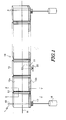
- Fig.1 shows an external prospective view for generally illustrating a containment boom 10 according to a preferred embodiment of the present invention.
- the containment boom 10 is developed on sea and is run on sea.
- a chain double-dashed line H represents a water line of the containment boom 10.
- the containment boom 10 of the present invention comprises a plurality of float units 12 each of which is coupled to an adjacent float unit 12 by a coupling portion 13.
- a main body of the float unit 12 comprises a housing composed of an oil shielding surface (a surface faced towards a front in Fig.1), a float portion 12a having a buoyant force, and a plummet portion 12b positioned under the float portion 12a.
- the housing is shaped into a flat box.
- the float unit 12a may have a few tens of centimeters to two meters in a vertical length and may have one meter to ten meters in a width. The vertical length and the width are not limited in the above-mentioned ranges, respectively.
- the float unit 12a and the plummet portion 12b are adjusted so as to position an approximate middle position of a vertical length of the oil shielding surface to the water line H.
- a balance is appropriately adjusted between the buoyant force of the float unit 12a and the weight of the plummet portion 12b. Therefore, an upper half-portion of the float unit 12 is positioned above the sea level and a lower half-portion of the float unit 12 is positioned under the sea level.
- the oil shielding surface perpendicular to the sea level functions as a barrier which extends above and under the sea level to prevent the oil from passing under the sea level and to prevent the oil from getting over the float unit 12.
- the float unit 12 It is possible for the float unit 12 to effetely synchronize with the heave of waves and currents. Even if a little delay occurs in the response of the float unit 12 under a hostile environment, there is not fear of oil leakage on the basis of an effect of the oil shielding surface having a large area. Under the circumstances, the float unit 12 is far superior to the conventional cylindrical float.
- the coupling portion 13 is a flexible coupling portion which is for varying a relative position between the adjacent float units 12.
- the coupling portion 13 has at least one fold which is extends towards a vertical direction.
- the coupling portion 13 is mounted over the entire vertical length of the float unit 12.
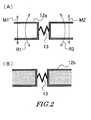
- Fig.2(A) shows a sectional view along an X-X line of Fig.1.
- Fig.2(B) shows a sectional view along a Y-Y line of Fig.1.
- the sectional view along the X-X line represents a part close to the coupling portion 13 between the adjacent units in the float portion 12a of the float unit 12, as shown in Fig.2(A).
- the float portion 12a has a hollow space which is for adding the buoyant force, as shown in the figure.
- the float portion 12a is made of synthetic resin foam to have the buoyant force.
- the coupling portion 13 has an accordion-fold shape having at least one fold portion and has flexibility.
- the adjacent float units 12 can relatively rotate about axes each of which extends towards a vertical direction, as shown by arrows R1 and R2.
- the adjacent float units 12 can relatively move towards front and rear directions, as shown by arrows M1 and M2, respectively.
- description will be made with reference to Fig.1. It is possible to the coupling portion to move as a folding fun motion in which the upper portion of the fold portion opens and the lower portion of the fold portion closes in the coupling portion 13. Alternatively, the upper portion of the fold portion may open and the lower portion of the fold portion may close in the coupling portion 13.
- the sectional view along the YY line represents a part close to the coupling portion 13 between the adjacent units in the plummet portion 12b of the float unit 12, as shown in Fig.2(B).
- the plummet portion 12b has a hollow housing. A material having a great specific gravity is filled in the bottom portion of the hollow housing.
- the plummet portion 12b is jointed to the float portion 12a which is separately formed from the plummet portion 12b.
- the plummet portion 12b may be made of metal.
- Each of the float unit and the coupling portion of the present invention is made of a material having endurance and strength with respect to a mechanical load such as bending, tensile, compression, and kink, taking use in sea into consideration. It is desired that the oil boom has a lightweight except the plummet portion 12b. For example, it is possible to use synthetic resin or metal in the float unit 12 and the coupling portion 13.
- At least one float unit 12 selected from a plurality of float units 12 has a lower plummet part 16 hanging from the float unit 12, an adjusting section 17 for adjusting the hanging length of the lower plummet part 16, and means 18 for remotely operating the adjusting section 17, in an embodiment of the present invention.
- the adjusting section 17 for adjusting the hanging length of the lower plummet part 16 may be, for example, a mechanism for running out and taking up a rope which is attached to the lower plummet part 16.
- the means 18 for remotely operating the adjusting section 17 may be, for example, an antenna for receiving a control signal which is for use in driving and stopping the adjusting section 17, in order to run out and take up the rope.
- the control device positioned on a ship or a land transmits the control signal to the means 18.
- the lower plummet part 16 Under control of the lower plummet part 16, the lower plummet part 16 is run out so that the oil boom is fixed at a predetermined location.
- the plummet part 16 is taken up according to need so that the oil boom is moved to another location.
- At least one float unit 12 selected from a plurality of float units 12 has a sensor 22 for detecting a relative position between the float unit 12 and the sea level and a screw 20 operative to moving the float unit 12 downwardly in accordance with a detection signal generated by the sensor 22, in another embodiment of the present invention.
- the sensor 22 may be attached at a position of water line H which is initially established (or the sensor 22 may be attached at a position slightly below the water line H).
- the sensor 22 detects that the float unit 12 is perfectly exposed from the sea level.
- the sensor 22 transmits an abnormal signal to a driving device which drives the screw 20. Responsive to the abnormal signal, the driving device drives the screw 20.
- the float unit abnormally floated from the sea level is forcefully sunk to the normal position.
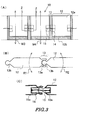
- Figs.3(A) to (C) show views for illustrating another embodiment of a coupling portion 13 of oil boom 10 of the present invention.
- Fig.3(A) shows a front view of the oil boom 10.
- the float unit 12 of Fig.3(A) has a structure similar to that of the float unit illustrated in Fig.1.
- the coupling portion 13 of Fig.3(A) is different in structure from the coupling portion illustrated in Fig.1.
- Fig.3(B) shows a top view of the oil boom 10.
- the coupling portion 13 comprises a rail member.
- the coupling portion 13 is formed by fitting a rail acceptance body 13a attached along a side surface of the float unit 12 to a rail acceptance body 13a attached another side surface of the float unit 12, between the adjacent float units.
- the adjacent float units 12 relatively rotate about axes each of which extends towards a vertical direction of each unit 12, as shown by arrows R1 and R2, respectively.
- the adjacent float units 12 can relatively move upwardly and downwardly, as shown by arrows M3 and M4 of Fig.3(A), respectively.
- the adjacent float units 12 are connected in their side surfaces by a position stabilizing member 15 which is formed by an elastic material, in order to prevent occurrence of excessive movements of the upward and downward directions that are shown by the arrows M3 and M4, respectively.
- the position stabilizing member 15 functions so as to restore variation of relative position between the adjacent float units 12 in the upward and downward directions.
- Fig.3(C) shows a sectional view along the Z-Z line and shows an attaching example for the position stabilizing member 15.
- vacant rooms 14 are formed near the central part of the side surface of the float unit 12. Both ends of the position stabilizing member 15 formed by the elastic material are fixed to the wall surfaces of the vacant rooms 14, respectively.
- a coil spring or a rubber may be used as the elastic material by which the position stabilizing member 15 is formed.
- Figs.4(A) and (B) show views for illustrating another example of the containment boom.
- Fig.4(A) shows a front view.
- Fig.4(B) shows a top view.
- the float unit 12 comprises the oil shielding surface, the float portion 12a and the plummet portion 12b as described in conjunction with Fig.1.
- the float unit 12 of Figs,4(A) and (B) has a housing whose thickness is comparatively thinner than that of the housing illustrated in Fig.1. In case of the thin housing, the adjacent float units 12 may be connected to one another by a single film material without the coupling portion 13 having the fold portion extending upwardly and downwardly.
- a restriction part may be formed between the shapes of each float unit 12 in case of integrally molding a several continuous float units 12 in a manufacturing method.
- the restriction part may be used as the coupling portion 13.
- the adjacent float units 12 can relatively rotate about the coupling portion 13 which is used as an axis, as shown by arrows R1 and R2, respectively.
- Figs.5(A) and (B) show views for describing a method of retracting the containment boom 10 of the present invention.
- Fig.5(A) shows a top face view for illustrating a state in which the containment boom 10 shown in Fig.1 is folded by turns.
- Fig.5(B) shows a top face view for illustrating a state in which the containment boom 10 shown in Fig.3 is rolled in a spiral shape.
- the containment boom of the present invention comprises a plurality of float units and a coupling portion by which adjacent float units are coupled to one another.
- Each of the float units comprises a housing having an oil shielding surface perpendicular to sea level, a float portion having a buoyant force, and a plummet portion positioned under the float portion.
- the float portion and the plummet portion are established so as to locate a water line to approximate middle position of vertical length of the oil shielding surface.
- the coupling portion is a flexible coupling portion for varying a relative position between the adjacent float units.
- the oil shielding surface to function as a barrier for certainly preventing the containment of oil spill, inasmuch as the float unit synchronizes with momentary violent movements of waves and currents. Furthermore, it is possible for the containment boom to be retracted in compact and it is possible for the containment boom to be developed and to be run at a high speed. In addition, it is possible to prevent an oil leakage inasmuch as the sensor detects that the float unit abnormally floats, and the float unit is forcibly sunk to be returned back to a normal position in accordance with a detection signal generated by the sensor.
Landscapes
- Engineering & Computer Science (AREA)
- General Engineering & Computer Science (AREA)
- Environmental & Geological Engineering (AREA)
- Mechanical Engineering (AREA)
- Civil Engineering (AREA)
- Structural Engineering (AREA)
- Level Indicators Using A Float (AREA)
- Cleaning Or Clearing Of The Surface Of Open Water (AREA)
- Removal Of Floating Material (AREA)
Applications Claiming Priority (2)
| Application Number | Priority Date | Filing Date | Title |
|---|---|---|---|
| JP2002369642A JP2003221823A (ja) | 2002-12-20 | 2002-12-20 | オイルフェンス |
| JP2002369642 | 2002-12-20 |
Publications (1)
| Publication Number | Publication Date |
|---|---|
| EP1431462A1 true EP1431462A1 (en) | 2004-06-23 |
Family
ID=27751512
Family Applications (1)
| Application Number | Title | Priority Date | Filing Date |
|---|---|---|---|
| EP03022414A Withdrawn EP1431462A1 (en) | 2002-12-20 | 2003-10-07 | Oil boom |
Country Status (3)
| Country | Link |
|---|---|
| US (1) | US6854927B2 (enExample) |
| EP (1) | EP1431462A1 (enExample) |
| JP (1) | JP2003221823A (enExample) |
Cited By (1)
| Publication number | Priority date | Publication date | Assignee | Title |
|---|---|---|---|---|
| WO2007065203A1 (en) * | 2005-12-05 | 2007-06-14 | David John Wilkie | Floating containment boom |
Families Citing this family (21)
| Publication number | Priority date | Publication date | Assignee | Title |
|---|---|---|---|---|
| FI117934B (fi) * | 2004-02-17 | 2007-04-30 | Finnketju Invest Oy | Kaavin |
| US7390141B2 (en) * | 2004-06-03 | 2008-06-24 | Rytand David H | Wave-attenuating system |
| JP2007077627A (ja) * | 2005-09-13 | 2007-03-29 | Chugoku Electric Power Co Inc:The | オイルフェンス及びその使用方法 |
| US7618214B2 (en) * | 2006-02-03 | 2009-11-17 | Maritime International, Inc. | Containment boom guide system and method |
| US20110042324A1 (en) * | 2007-02-02 | 2011-02-24 | Matthew Hughes | System and method for water restoration |
| US7550079B2 (en) * | 2007-02-02 | 2009-06-23 | Matthew Hughes | System and method for water restoration |
| US20090311047A1 (en) * | 2008-06-11 | 2009-12-17 | Sky Bleu Martin | Containment Boom and Standoff |
| US20110110721A1 (en) * | 2008-06-11 | 2011-05-12 | Sky Bleu Martin | Local Containment Boom and Standoff (Enviro Boom) |
| KR100997428B1 (ko) | 2008-10-28 | 2010-12-07 | 한국해양연구원 | 오염차단막 위치 및 형상 모니터링 시스템과 이를 이용한 모니터링 방법 |
| US8303212B2 (en) * | 2010-05-06 | 2012-11-06 | Lara Kim A | Boom mooring system |
| EP2441891A1 (en) * | 2010-10-12 | 2012-04-18 | Vetco Gray Controls Limited | Oil retention booms |
| US20120141205A1 (en) * | 2010-12-03 | 2012-06-07 | Intelligent Organics Limited | Mobile marine barrier system |
| US8974143B2 (en) * | 2011-03-31 | 2015-03-10 | Deep Down, Inc. | Offshore atoll system and related methods of use |
| GB2487101B (en) | 2011-07-04 | 2014-01-08 | Intelligent Organics Ltd | Mobile marine barrier |
| CN102493414A (zh) * | 2011-12-30 | 2012-06-13 | 天津汉海环保设备有限公司 | 设有内包式压载链的高强度围油栏 |
| US8398334B1 (en) * | 2012-04-24 | 2013-03-19 | Robert Doyle | Self-positioning subsea oil spill containment system |
| WO2014036189A2 (en) | 2012-08-28 | 2014-03-06 | Zlotkin Michael | Buoyant containment and/or filtration |
| US10100480B2 (en) | 2016-06-01 | 2018-10-16 | Trendsetter Engineering, Inc. | Subsea booming system and method for deploying a subsea booming system |
| US10323372B1 (en) | 2018-02-21 | 2019-06-18 | Rain Turtle Services, Llc | Floating turbidity barrier |
| US11879222B2 (en) * | 2018-04-12 | 2024-01-23 | Woosb Ltd | Oil spill barrier |
| KR102933984B1 (ko) | 2025-08-27 | 2026-03-04 | (주)세일종합기술공사 | 위치이동 및 전개가 가능한 항만오염방지용 오탁 방지막 설치 장치 및 이를 사용한 항만오염방지용 오탁 방지막 설치 방법 |
Citations (3)
| Publication number | Priority date | Publication date | Assignee | Title |
|---|---|---|---|---|
| US4033137A (en) * | 1973-07-12 | 1977-07-05 | Geist James J | Articulated floating barrier |
| FR2395358A2 (fr) * | 1977-06-23 | 1979-01-19 | Rhin Et Rhone Sa | Barrage pour lutter contre la pollution des eaux par les hydrocarbures |
| GB1565600A (en) * | 1977-12-06 | 1980-04-23 | Mitsubishi Heavy Ind Ltd | Floating barrier for oil |
Family Cites Families (15)
| Publication number | Priority date | Publication date | Assignee | Title |
|---|---|---|---|---|
| GB1465634A (en) * | 1973-06-21 | 1977-02-23 | Grihangne A | Floating marine boom |
| US3906732A (en) * | 1975-01-10 | 1975-09-23 | Goodrich Co B F | Shipside oil barrier seal |
| US3958521A (en) * | 1975-05-30 | 1976-05-25 | Memoli Steven J | Deep sea tank and seaport system |
| US4290714A (en) * | 1979-12-03 | 1981-09-22 | Western Geophysical Co. Of America | Marine oil leak containment and recovery apparatus |
| US4627766A (en) * | 1986-03-13 | 1986-12-09 | Marquet Maurice C | Multi-purpose marine barrier system |
| US5000616A (en) * | 1990-07-02 | 1991-03-19 | Atlantic Richfield | Oil containment boom |
| US5407301A (en) * | 1992-12-16 | 1995-04-18 | Petroleum Recovery Technologies, Inc. | Oil spill recovery system |
| US5509756A (en) * | 1994-03-04 | 1996-04-23 | Tcom, L.P. | Oil boom end connector |
| JP3332718B2 (ja) | 1995-09-28 | 2002-10-07 | 三菱重工業株式会社 | オイルフェンス装置 |
| JPH1018173A (ja) | 1996-07-02 | 1998-01-20 | Unitika Glass Fiber Kk | ガラスクロスの接続方法 |
| JPH1018273A (ja) | 1996-07-04 | 1998-01-20 | Toyota Auto Body Co Ltd | オイルフェンスおよびオイルフェンスの護岸への取付構造 |
| JPH10292357A (ja) | 1997-04-11 | 1998-11-04 | Sumitomo Rubber Ind Ltd | オイルフェンス |
| JPH1143925A (ja) | 1997-07-28 | 1999-02-16 | Hokuriku Electric Power Co Inc:The | オイルフェンス |
| JPH11100833A (ja) | 1997-09-29 | 1999-04-13 | Nakamura Bussan Kk | オイルフェンス |
| US20030185629A1 (en) * | 2002-04-02 | 2003-10-02 | Yodock Leo J. | Floating barrier wall |
-
2002
- 2002-12-20 JP JP2002369642A patent/JP2003221823A/ja active Pending
-
2003
- 2003-09-30 US US10/675,767 patent/US6854927B2/en not_active Expired - Fee Related
- 2003-10-07 EP EP03022414A patent/EP1431462A1/en not_active Withdrawn
Patent Citations (3)
| Publication number | Priority date | Publication date | Assignee | Title |
|---|---|---|---|---|
| US4033137A (en) * | 1973-07-12 | 1977-07-05 | Geist James J | Articulated floating barrier |
| FR2395358A2 (fr) * | 1977-06-23 | 1979-01-19 | Rhin Et Rhone Sa | Barrage pour lutter contre la pollution des eaux par les hydrocarbures |
| GB1565600A (en) * | 1977-12-06 | 1980-04-23 | Mitsubishi Heavy Ind Ltd | Floating barrier for oil |
Cited By (1)
| Publication number | Priority date | Publication date | Assignee | Title |
|---|---|---|---|---|
| WO2007065203A1 (en) * | 2005-12-05 | 2007-06-14 | David John Wilkie | Floating containment boom |
Also Published As
| Publication number | Publication date |
|---|---|
| US20040120770A1 (en) | 2004-06-24 |
| US6854927B2 (en) | 2005-02-15 |
| JP2003221823A (ja) | 2003-08-08 |
Similar Documents
| Publication | Publication Date | Title |
|---|---|---|
| US6854927B2 (en) | Containment boom | |
| AU564298B2 (en) | Reel mountable boom arrangement | |
| CN112462429B (zh) | 海底地震仪布放回收器及方法 | |
| CA2288571C (en) | Floated gimbal optical platform | |
| US20080016860A1 (en) | Wave powered generation | |
| BRPI0708432A2 (pt) | navio com uma plataforma de compensação de movimento, plataforma de movimento, métodos para compensar movimentos de um navio e para movimentar uma plataforma de stewart e uso de uma plataforma de stewart | |
| JP2008157642A (ja) | 津波・波浪観測用ブイ | |
| CN1312881A (zh) | 竖井管的相关装置 | |
| US4391554A (en) | Mooring system bearing for a tensioned leg platform | |
| EP1080007B1 (en) | Transfer pipe system | |
| CA2511362C (en) | Deep water flexible riser protection | |
| KR101722202B1 (ko) | 석션 파일 앵커 | |
| HK1066839A (en) | Oil boom | |
| WO2005085632A1 (en) | Improved wave energy converter (wec) device and system | |
| EP0087321B1 (en) | Offshore structure and method of constructing same | |
| NZ200196A (en) | Truss array for supporting devices horizontally in fluid medium | |
| US3802201A (en) | Rough water barrier | |
| JP2025143427A (ja) | 浮力がある回転可能な海洋変換器 | |
| EP0252544B1 (en) | Mooring device | |
| JP2009216238A (ja) | 免震装置、滑り支承また免震構造 | |
| US20110110721A1 (en) | Local Containment Boom and Standoff (Enviro Boom) | |
| CA2629951C (en) | Communication float | |
| JP2845272B2 (ja) | 展開型水中探知装置 | |
| JP2695673B2 (ja) | 浅水域用緊張係留装置 | |
| JP3477341B2 (ja) | 浮体係留装置 |
Legal Events
| Date | Code | Title | Description |
|---|---|---|---|
| PUAI | Public reference made under article 153(3) epc to a published international application that has entered the european phase |
Free format text: ORIGINAL CODE: 0009012 |
|
| AK | Designated contracting states |
Kind code of ref document: A1 Designated state(s): AT BE BG CH CY CZ DE DK EE ES FI FR GB GR HU IE IT LI LU MC NL PT RO SE SI SK TR |
|
| AX | Request for extension of the european patent |
Extension state: AL LT LV MK |
|
| 17P | Request for examination filed |
Effective date: 20041208 |
|
| AKX | Designation fees paid |
Designated state(s): DE FR GB IT NL |
|
| REG | Reference to a national code |
Ref country code: HK Ref legal event code: DE Ref document number: 1066839 Country of ref document: HK |
|
| RBV | Designated contracting states (corrected) |
Designated state(s): DE FR GB IT NL |
|
| STAA | Information on the status of an ep patent application or granted ep patent |
Free format text: STATUS: THE APPLICATION IS DEEMED TO BE WITHDRAWN |
|
| 18D | Application deemed to be withdrawn |
Effective date: 20060314 |
|
| REG | Reference to a national code |
Ref country code: HK Ref legal event code: WD Ref document number: 1066839 Country of ref document: HK |