EP1431225A1 - Aufzug mit einem hydraulischen Antrieb - Google Patents
Aufzug mit einem hydraulischen Antrieb Download PDFInfo
- Publication number
- EP1431225A1 EP1431225A1 EP03028882A EP03028882A EP1431225A1 EP 1431225 A1 EP1431225 A1 EP 1431225A1 EP 03028882 A EP03028882 A EP 03028882A EP 03028882 A EP03028882 A EP 03028882A EP 1431225 A1 EP1431225 A1 EP 1431225A1
- Authority
- EP
- European Patent Office
- Prior art keywords
- valve
- elevator
- hydraulic
- drive
- elevator according
- Prior art date
- Legal status (The legal status is an assumption and is not a legal conclusion. Google has not performed a legal analysis and makes no representation as to the accuracy of the status listed.)
- Granted
Links
- 238000005259 measurement Methods 0.000 claims abstract description 11
- 238000000034 method Methods 0.000 claims abstract description 7
- 239000012530 fluid Substances 0.000 claims description 10
- 238000010276 construction Methods 0.000 claims description 3
- 238000013461 design Methods 0.000 description 4
- 238000006073 displacement reaction Methods 0.000 description 4
- 230000001105 regulatory effect Effects 0.000 description 3
- 239000000725 suspension Substances 0.000 description 3
- 230000032683 aging Effects 0.000 description 2
- 238000013016 damping Methods 0.000 description 2
- 238000001514 detection method Methods 0.000 description 2
- 230000002349 favourable effect Effects 0.000 description 2
- 229910000831 Steel Inorganic materials 0.000 description 1
- 230000006978 adaptation Effects 0.000 description 1
- 230000002411 adverse Effects 0.000 description 1
- 230000001143 conditioned effect Effects 0.000 description 1
- 230000001276 controlling effect Effects 0.000 description 1
- 230000006866 deterioration Effects 0.000 description 1
- 238000011161 development Methods 0.000 description 1
- 230000018109 developmental process Effects 0.000 description 1
- 238000005516 engineering process Methods 0.000 description 1
- 230000010354 integration Effects 0.000 description 1
- 238000012423 maintenance Methods 0.000 description 1
- 230000007257 malfunction Effects 0.000 description 1
- 239000010959 steel Substances 0.000 description 1
Images


Classifications
-
- B—PERFORMING OPERATIONS; TRANSPORTING
- B66—HOISTING; LIFTING; HAULING
- B66B—ELEVATORS; ESCALATORS OR MOVING WALKWAYS
- B66B1/00—Control systems of elevators in general
- B66B1/24—Control systems with regulation, i.e. with retroactive action, for influencing travelling speed, acceleration, or deceleration
Definitions
- the invention relates to an elevator with a hydraulic Drive, measuring signal sensors for the detection of System states and at least one electronically controllable Valve with a regulator, which is a device for Feedback of at least the measurement signals of the hydraulic pressure and the valve piston position.
- Hydraulic lifts are in different configurations known.
- a flexible drive means that extends from the suspension cable of the elevator differentiates, drives and thus to move the elevator.
- a hydraulic drive both linear cylinders and hydraulic rotary motors to use.
- Hydraulic control valves are sometimes used in hydraulic elevators used. This is usually a system size measured and fed to a controller, which thereby possible disturbance variables are calculated and the hydraulic flow by changing the hydraulic valve position to compensate the disturbances compensated. In addition to the Regulation of the oil flow also regulation depending realized from the elevator position.
- DE 696 02 923 T2 describes an electrohydraulic control valve known that the flow rate and / or pressure to a hydraulic consumer depending on the recorded valve part position, the recorded pressures and further measured states and a control signal controls. Through an integrated control circuit quick and accurate control of the fluid reached.
- the invention is based on the task, to improve a hydraulic elevator of this type.
- This task is accomplished with an elevator of the type mentioned at the beginning Art solved according to the invention in that at least a 3/3-way valve is provided to control the drive is.
- the drive as a hydraulic rotary motor or designed as a hydraulic linear drive is.
- the drive may be advantageous. So are Rotary motors at high head and high driving speed of the elevator makes sense.
- a hydraulic one Linear drive is able to handle particularly high loads move, both the maximum head and the maximum driving speed is limited.
- each a 3/3-way valve for the Inlet and outlet of the hydraulic rotary motor provided is.
- the use of a separate valve offers for both connections of the drive in comparison to the conventional construction with a combined valve
- a number of advantages for the inlet and outlet That's the way it is possible to separate the pressure in both lines adjust from each other, for example for jerk-free It is necessary to start the elevator from a standstill is.
- possible leakage losses in the drive fully compensate.
- what with a four-quadrant operation of the elevator causes the engine to depend on the direction of travel and loading condition once as a drive and once is used as a brake, can be particularly fast and be reacted gently.
- the drive is preferably provided with a mechanical holding device, in particular a brake or a holding valve, fitted.
- the at least one control valve spatially provided directly on the drive possibly in a flange design is.
- Such an attachment to the drive if possible with particularly rigid connections ensures that no vibrations in this part of the hydraulic circuit may occur.
- the set by the control valve Pressure medium flows go directly to the drive without that vibrations form in long supply lines can affect the stability of the overall system. Overall, the control properties are hereby clearly improved.
- a further embodiment of the invention is characterized in that that the drive in the shaft head or Shaft floor is arranged.
- the elevator drive can be moved to an extra machine room to be dispensed with.
- Such in many conventional elevators necessary machine rooms increase the cost of the overall system considerably, so a waiver of this is definitely desirable.
- By using a electronically controlled hydraulic drive drives of this type can be realized.
- An embodiment of the invention is characterized by this from that the counterweight is the same mass as the elevator plus half its maximum load.
- a counterweight is a four-quadrant operation of the elevator possible.
- the engine is both as a drive as well as a brake depending on the load the elevator car used. Overall, such offers Design of the elevator system has the advantage that the drive can be built very small and the system is a good one Owns energy utilization.
- One embodiment of the invention provides that Measuring signal sensor for the detection of hydraulic fluid temperature and / or elevator position and / or possibly further System states are provided. So a constant one Driving speed and accurate positioning of the elevator at the stops. Besides, will the system security increases because of fluid leaks or others Exceptional conditions recognized and compensated for if possible can be.
- the controller has a cascade structure, in which the control of valve piston position and hydraulic pressure in the inner control loop and occurring control errors based on the other measured system states be compensated in an outer slow control loop for example, an exact entrance at the stops to ensure.
- an outer slow control loop for example, an exact entrance at the stops to ensure.
- valve is a device for Has compensation of the hydraulic fluid temperature.
- At least one electronic Processor unit with the regulator and / or for control of the valve and / or the holding device is provided.
- the use of electronic processor units, for example in the form of plug-in cards or other such components enables precise control of the elevator in all operating areas.
- the connection to higher-level system controls is easily possible. By adapting the operating programs, it can be expanded Cover areas of systems and plant configurations and quickly adapt to changing circumstances.
- the invention also relates to a Method for controlling a hydraulically driven Elevator.
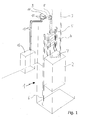
- An elevator generally designated 1, according to the invention consists of an elevator car 2, which has a flexible suspension cable 3 connected to a counterweight 4 is. Weight 4 is in the elevator shaft Rails 5 guided vertically.
- the elevator car 2 is slidably mounted in guide rails 6.
- a flat belt can also be used Steel wire inserts are used.
- the flexible suspension cable 3 is over several deflecting rollers 7 guided and fastened with its two ends in the shaft head. It runs between the elevator car and the counterweight via the traction sheave 8 by a hydraulic rotary motor 9 is driven.
- a hydraulic rotary motor 9 Located on drive 9 an electronic valve 10, which is rigid via two Lines 11 is connected to the drive motor 9.
- FIG. 2 An alternative embodiment with a hydraulic Linear drive is shown in more detail in Fig. 2. Doing so the elevator car 2 can be displaced again in guide rails 6 stored and by a plunger hydraulic cylinder 9a vertically shifted.
- the hydraulic valve 10 is arranged in close proximity to the pressure medium supply 12 and via a single pressure medium line 11a with the Hydraulic cylinder 9a connected.
- valve 10 is controlled by a valve processor 26, which gets its control signals from a system processor 27 receives.
- a higher-level system control 28 coordinates the overall control of the system.
- a hydraulic linear drive 9a becomes the drive of the elevator.
- the hydraulic supply 12 consists of a hydraulic reservoir 14 and one driven by a motor 15 load-sensing pump 16, the 17 at the high pressure port Operating pressure of the system provides.
- a working pressure relief valve 18 ensures that the on Connection 17 available operating pressure of the Plant is kept constant. To hedge is still a maximum pressure relief valve 19 is present, the Protects the system from dangerous overpressure conditions.
- the Returning oil is from the low pressure port 20 in the Hydraulic reservoir 14 returned.
- the electronically controllable valve 10 consists in its simple design for a linear drive from one 3/3-way valve 21, which has an electronically controllable 4/3-way pilot valve 22 is adjusted.
- On the control valve 21 is a displacement sensor 23 for measuring the Spool position.
- a pressure sensor 24 is used Measurement of the pressure on the drive side and a temperature measuring element 25 for determining the hydraulic fluid temperature available.
- the measurement signals from the sensors are stored in a valve processor 26 passed, which includes the controller and on whose control output is the electrical control input 27 of the Pilot valve 22 is connected.
- the setpoint sizes for the piston position and the various system pressures are specified by the system processor 27, which in Dependency on user preferences and by the here System controller 28, not shown, predefined further external system states calculate the necessary control variables and passes to the valve processor 26.
- a releasable check valve 29 is provided, by an electrically operated control valve 30 can be operated. There is also a shut-off valve 31 provided for maintenance work and the like.
- the hydraulic control for operation with one Hydraulic motor 9 is shown in more detail in FIG. 4. It is to stop the elevator at a certain position the drive roller 8 a hydraulically operated brake 32 provided by an electrically operated control valve 33 is operated. The brake is used to protect the Lift before crashes in the event of malfunctions in the drive also used to hold the elevator at a standstill.
- the construction of the hydraulic circuit is similar to that in FIG. 3 shown. However, here are two main control valves 21a and 21b are provided, each with its own electronically operated pilot valve 22a and 22b controlled become.
- the displacement sensors 23a and 23b, the pressure sensors 24a and 24b and the temperature measuring elements 25a and 25b are also for each of the two control valves 21a and 21b available.
- the valves are on the inlet side each with the high pressure connection 20 and with the low pressure connection 17 of the hydraulic supply 12 connected.
- the control valves 21a and 21b are over two stopcocks 31a and 31b by two short rigid Lines 11 coupled to the hydraulic motor 9. There is one Valve 21a to the inlet and a valve to the outlet of the Hydromotor 9 connected.
- the measurement signals from the sensors in the hydraulic circuit are fed back to the valve processor 26, which the Control variables for the control inputs 27a and 27b of the pilot valves 22a and 22b depending on the measured Sizes calculated.
- the system processor 27 calculates analogously the necessary depending on other system sizes Hydraulic flows to and from the engine 9. For more details Control of the elevator speed and position of the Hydraulic motor 9 also has a sensor 34, whose signal also from the system computer 27 for control the elevator position and speed is used.
- the invention is not based on the foregoing Embodiments limited, but in many Modifiable in terms, without leaving the basic idea. So are in addition to the types of drives described further hydraulic drives possible. Also the pressure supply can take on different designs in order to to achieve optimal results for the existing system. There is also a version for the linear drive two control valves possible, one with a cascade Building a favorable driving behavior for Slow and fast driving is achieved.
Landscapes
- Engineering & Computer Science (AREA)
- Automation & Control Theory (AREA)
- Types And Forms Of Lifts (AREA)
- Elevator Control (AREA)
- Fluid-Pressure Circuits (AREA)
- Valve Device For Special Equipments (AREA)
- Actuator (AREA)
Abstract
Description
- Fig. 1
- eine schematische, dreidimensionale Ansicht eines Aufzuges nach der Erfindung mit hydraulischem Rotationsmotor,
- Fig. 2
- eine schematische dreidimensionale Ansicht eines Aufzuges nach der Erfindung mit hydraulischem Linearantrieb,
- Fig. 3
- eine Darstellung der erfindungsgemäßen Hydraulikschaltung für einen hydraulischen Linearantrieb sowie in
- Fig. 4
- eine erfindungsgemäße Hydraulikschaltung für einen hydraulischen Rotationsmotor.
Claims (12)
- Aufzug mit einem hydraulischen Antrieb, Messsignalaufnehmern zur Erfassung von Systemzuständen und wenigstens einem elektronisch steuerbaren Ventil mit einem Regler, der eine Einrichtung zur Rückführung wenigstens der Messsignale des Hydraulikdruckes und der Ventilkolbenstellung aufweist,
dadurch gekennzeichnet, dass wenigstens ein 3/3-Wege Ventil (21,21a) zur Ansteuerung des Antriebes vorgesehen ist. - Aufzug nach Anspruch 1,
dadurch gekennzeichnet, dass der Antrieb als hydraulischer Rotationsmotor (9) oder als hydraulischer Linearantrieb (9a) ausgebildet ist. - Aufzug nach Anspruch 2,
dadurch gekennzeichnet, dass jeweils ein 3/3-Wege Ventil (21a,21b) für den Zu- und den Ablauf des hydraulischen Rotationsmotors (9) vorgesehen ist. - Aufzug nach einem der Ansprüche 1 bis 3,
dadurch gekennzeichnet, dass der Antrieb mit einer mechanischen Haltevorrichtung, insbesondere einer Bremse (8) oder einem Halteventil (29), ausgestattet ist. - Aufzug nach einem der vorangehenden Ansprüche,
dadurch gekennzeichnet, dass das wenigstens eine Ventil (10) räumlich unmittelbar am Antrieb (9,9a) ggf. in Flanschbauweise vorgesehen ist. - Aufzug nach einem der vorangehenden Ansprüche,
dadurch gekennzeichnet, dass der Antrieb (9,9a) im Schachtkopf oder Schachtboden angeordnet ist. - Aufzug nach einem der vorangehenden Ansprüche,
dadurch gekennzeichnet, dass das Gegengewicht (4) die gleiche Masse wie der Aufzug (2) plus seiner halben Maximalzuladung aufweist. - Aufzug nach einem der vorangehenden Ansprüche,
dadurch gekennzeichnet, dass Messsignalaufnehmer (23,24,25,34,34a) zur Erfassung von Hydraulikfluidtemperatur und/oder Aufzugposition und/oder ggf. weiterer Systemzustände vorgesehen sind. - Aufzug nach einem der vorangehenden Ansprüche,
dadurch gekennzeichnet, dass das Ventil (10) eine Einrichtung zur Kompensation der Hydraulikfluidtemperatur aufweist. - Aufzug nach einem der vorangehenden Ansprüche,
dadurch gekennzeichnet, dass wenigstens eine elektronische Prozessoreinheit mit dem Regler und/oder zur Steuerung des Ventils und/oder der Haltevorrichtung (26,27,28) vorgesehen ist. - Verfahren zur Steuerung eines hydraulisch angetriebenen Aufzuges nach Anspruch 1 oder einem der folgenden,
dadurch gekennzeichnet, dass die Messsignale des Hydraulikdruckes und der Ventilkolbenstellung im und/oder am Ventil (10) aufgenommen werden und damit der Regler das Ventil so steuert, dass sich ein zur Erreichung eines Soll-Systemzustandes des Aufzuges (2) nötiger Hydraulikfluss einstellt. - Verfahren nach Anspruch 11,
dadurch gekennzeichnet, dass die Messsignale von weiteren Systemzuständen, insbesondere der Aufzugsposition, aufgenommen werden, der Regler damit einen Regelfehler durch den Vergleich des Ist-Zustandes mit dem Soll-Zustand des Aufzuges bestimmt und mit dem Ventil (10) diesen Regelfehler durch Anpassung des Hydraulikflusses zur Erreichung des Sollzustandes kompensiert.
Applications Claiming Priority (2)
| Application Number | Priority Date | Filing Date | Title |
|---|---|---|---|
| DE10259146A DE10259146A1 (de) | 2002-12-18 | 2002-12-18 | Aufzug mit einem hydraulischen Antrieb |
| DE10259146 | 2002-12-18 |
Publications (2)
| Publication Number | Publication Date |
|---|---|
| EP1431225A1 true EP1431225A1 (de) | 2004-06-23 |
| EP1431225B1 EP1431225B1 (de) | 2007-02-14 |
Family
ID=32336428
Family Applications (1)
| Application Number | Title | Priority Date | Filing Date |
|---|---|---|---|
| EP03028882A Expired - Lifetime EP1431225B1 (de) | 2002-12-18 | 2003-12-16 | Aufzug mit einem hydraulischen Antrieb |
Country Status (3)
| Country | Link |
|---|---|
| EP (1) | EP1431225B1 (de) |
| AT (1) | ATE353847T1 (de) |
| DE (2) | DE10259146A1 (de) |
Citations (2)
| Publication number | Priority date | Publication date | Assignee | Title |
|---|---|---|---|---|
| DE2646294A1 (de) * | 1976-10-14 | 1978-04-20 | Haushahn C Gmbh Co | Hydraulische antriebsvorrichtung fuer einen aufzug |
| US4205592A (en) * | 1976-12-24 | 1980-06-03 | Beringer-Hydraulik Gmbh | Hydraulic control system |
Family Cites Families (2)
| Publication number | Priority date | Publication date | Assignee | Title |
|---|---|---|---|---|
| DE3629032C2 (de) * | 1986-08-27 | 1994-02-03 | Haushahn C Gmbh Co | Hebezeug, insbesondere Aufzug |
| GB9503854D0 (en) * | 1995-02-25 | 1995-04-19 | Ultra Hydraulics Ltd | Electrohydraulic proportional control valve assemblies |
-
2002
- 2002-12-18 DE DE10259146A patent/DE10259146A1/de not_active Withdrawn
-
2003
- 2003-12-16 DE DE50306487T patent/DE50306487D1/de not_active Expired - Lifetime
- 2003-12-16 AT AT03028882T patent/ATE353847T1/de not_active IP Right Cessation
- 2003-12-16 EP EP03028882A patent/EP1431225B1/de not_active Expired - Lifetime
Patent Citations (2)
| Publication number | Priority date | Publication date | Assignee | Title |
|---|---|---|---|---|
| DE2646294A1 (de) * | 1976-10-14 | 1978-04-20 | Haushahn C Gmbh Co | Hydraulische antriebsvorrichtung fuer einen aufzug |
| US4205592A (en) * | 1976-12-24 | 1980-06-03 | Beringer-Hydraulik Gmbh | Hydraulic control system |
Also Published As
| Publication number | Publication date |
|---|---|
| ATE353847T1 (de) | 2007-03-15 |
| DE50306487D1 (de) | 2007-03-29 |
| EP1431225B1 (de) | 2007-02-14 |
| DE10259146A1 (de) | 2004-07-15 |
Similar Documents
| Publication | Publication Date | Title |
|---|---|---|
| DE102012207880B4 (de) | Hydraulikantriebsgerät für eine Arbeitsmaschine | |
| EP1664551B1 (de) | Steueranordnung und verfahren zur druckmittelversorgung von zumindest zwei hydraulischen verbrauchern | |
| DE69306738T2 (de) | Hydraulisches antriebsystem | |
| DE3644736C2 (de) | Steueranordnung für mindestens zwei von mindestens einer Pumpe gespeiste hydraulische Verbraucher | |
| DE2514624C3 (de) | Steuereinrichtung für mindestens einen hydraulisch betriebenen doppeltwirkenden Verbraucher | |
| EP2541072B1 (de) | Steueranordnung und Verfahren zum Ansteuern von mehreren hydraulischen Verbrauchern | |
| DE3600364A1 (de) | Verfahren und vorrichtung zum ausgleich des auf einen hydraulischen antrieb wirkenden veraenderlichen gewichtes einer masse, insbesondere fuer den senkrecht stehenden antriebszylinder einer laeppmaschine | |
| DE3218077A1 (de) | Elektromechanische steuerung fuer hydraulische aufzuege | |
| DE20208577U1 (de) | Elektrohydraulische Hubsteuervorrichtung für Flurförerfahrzeuge | |
| DE102021209707B4 (de) | Auslegerhebesystem | |
| EP0305761B1 (de) | Sekundärgeregeltes hydrostatisches Getriebe mit offenem Kreislauf | |
| DE69014583T2 (de) | Hydraulisches Aufzugsteuerventil. | |
| EP3988801A1 (de) | Verfahren zum betreiben eines hydraulischen antriebs | |
| EP1017942B1 (de) | Regeleinrichtung für eine verstellbare hydropumpe mit mehreren verbrauchern | |
| DE1176443B (de) | Anordnung zum selbsttaetigen Regeln von Fluessig-keitsgetrieben nach dem Verdraengungsprinzip | |
| WO1986004963A1 (fr) | Soupape proportionnelle avec precharge variable du ressort d'equilibrage non proportionnelle a la pression de la charge | |
| EP1431225B1 (de) | Aufzug mit einem hydraulischen Antrieb | |
| DE2245866A1 (de) | Vorrichtung zum ausgleich der spindelbelastungen bei zweistaender-maschinen | |
| DE4230183A1 (de) | Steuervorrichtung fuer wenigstens einen hydromotor | |
| DE3644737C2 (de) | Steueranordnung für mindestens zwei von mindestens einer Pumpe gespeiste hydraulische Verbraucher | |
| DE3609399A1 (de) | Hydrauliksystem | |
| DE102013007292B4 (de) | Verfahren zur Geschwindigkeitsregelung einer Klemm- und Hub-Vorrichtung sowie Regelvorrichtung zur Durchführung des Verfahrens | |
| EP1780171B1 (de) | Hubmast für Stapler | |
| EP2529821A1 (de) | Hydraulisches Antriebssystem für eine Schauspielbühne mit drehzahlverstellbarer Hydraulikpumpe als Steuerelement | |
| DE4219787C1 (de) | Fahrzeug mit batterie-elektrischem Fahr-Antrieb, insbesondere Hublader |
Legal Events
| Date | Code | Title | Description |
|---|---|---|---|
| PUAI | Public reference made under article 153(3) epc to a published international application that has entered the european phase |
Free format text: ORIGINAL CODE: 0009012 |
|
| AK | Designated contracting states |
Kind code of ref document: A1 Designated state(s): AT BE BG CH CY CZ DE DK EE ES FI FR GB GR HU IE IT LI LU MC NL PT RO SE SI SK TR |
|
| AX | Request for extension of the european patent |
Extension state: AL LT LV MK |
|
| 17P | Request for examination filed |
Effective date: 20041217 |
|
| AKX | Designation fees paid |
Designated state(s): AT BE BG CH CY CZ DE DK EE ES FI FR GB GR HU IE IT LI LU MC NL PT RO SE SI SK TR |
|
| GRAP | Despatch of communication of intention to grant a patent |
Free format text: ORIGINAL CODE: EPIDOSNIGR1 |
|
| GRAS | Grant fee paid |
Free format text: ORIGINAL CODE: EPIDOSNIGR3 |
|
| GRAA | (expected) grant |
Free format text: ORIGINAL CODE: 0009210 |
|
| AK | Designated contracting states |
Kind code of ref document: B1 Designated state(s): AT BE BG CH CY CZ DE DK EE ES FI FR GB GR HU IE IT LI LU MC NL PT RO SE SI SK TR |
|
| PG25 | Lapsed in a contracting state [announced via postgrant information from national office to epo] |
Ref country code: DK Free format text: LAPSE BECAUSE OF FAILURE TO SUBMIT A TRANSLATION OF THE DESCRIPTION OR TO PAY THE FEE WITHIN THE PRESCRIBED TIME-LIMIT Effective date: 20070214 Ref country code: IE Free format text: LAPSE BECAUSE OF FAILURE TO SUBMIT A TRANSLATION OF THE DESCRIPTION OR TO PAY THE FEE WITHIN THE PRESCRIBED TIME-LIMIT Effective date: 20070214 Ref country code: SI Free format text: LAPSE BECAUSE OF FAILURE TO SUBMIT A TRANSLATION OF THE DESCRIPTION OR TO PAY THE FEE WITHIN THE PRESCRIBED TIME-LIMIT Effective date: 20070214 Ref country code: FI Free format text: LAPSE BECAUSE OF FAILURE TO SUBMIT A TRANSLATION OF THE DESCRIPTION OR TO PAY THE FEE WITHIN THE PRESCRIBED TIME-LIMIT Effective date: 20070214 |
|
| REG | Reference to a national code |
Ref country code: GB Ref legal event code: FG4D Free format text: NOT ENGLISH |
|
| REG | Reference to a national code |
Ref country code: CH Ref legal event code: EP |
|
| REF | Corresponds to: |
Ref document number: 50306487 Country of ref document: DE Date of ref document: 20070329 Kind code of ref document: P |
|
| REG | Reference to a national code |
Ref country code: IE Ref legal event code: FG4D Free format text: LANGUAGE OF EP DOCUMENT: GERMAN |
|
| PG25 | Lapsed in a contracting state [announced via postgrant information from national office to epo] |
Ref country code: SE Free format text: LAPSE BECAUSE OF FAILURE TO SUBMIT A TRANSLATION OF THE DESCRIPTION OR TO PAY THE FEE WITHIN THE PRESCRIBED TIME-LIMIT Effective date: 20070514 |
|
| PG25 | Lapsed in a contracting state [announced via postgrant information from national office to epo] |
Ref country code: BG Free format text: LAPSE BECAUSE OF EXPIRATION OF PROTECTION Effective date: 20070515 |
|
| PG25 | Lapsed in a contracting state [announced via postgrant information from national office to epo] |
Ref country code: ES Free format text: LAPSE BECAUSE OF FAILURE TO SUBMIT A TRANSLATION OF THE DESCRIPTION OR TO PAY THE FEE WITHIN THE PRESCRIBED TIME-LIMIT Effective date: 20070525 |
|
| PG25 | Lapsed in a contracting state [announced via postgrant information from national office to epo] |
Ref country code: PT Free format text: LAPSE BECAUSE OF FAILURE TO SUBMIT A TRANSLATION OF THE DESCRIPTION OR TO PAY THE FEE WITHIN THE PRESCRIBED TIME-LIMIT Effective date: 20070716 |
|
| GBV | Gb: ep patent (uk) treated as always having been void in accordance with gb section 77(7)/1977 [no translation filed] |
Effective date: 20070214 |
|
| REG | Reference to a national code |
Ref country code: IE Ref legal event code: FD4D |
|
| EN | Fr: translation not filed | ||
| PG25 | Lapsed in a contracting state [announced via postgrant information from national office to epo] |
Ref country code: GB Free format text: LAPSE BECAUSE OF FAILURE TO SUBMIT A TRANSLATION OF THE DESCRIPTION OR TO PAY THE FEE WITHIN THE PRESCRIBED TIME-LIMIT Effective date: 20070214 Ref country code: SK Free format text: LAPSE BECAUSE OF FAILURE TO SUBMIT A TRANSLATION OF THE DESCRIPTION OR TO PAY THE FEE WITHIN THE PRESCRIBED TIME-LIMIT Effective date: 20070214 |
|
| PLBE | No opposition filed within time limit |
Free format text: ORIGINAL CODE: 0009261 |
|
| STAA | Information on the status of an ep patent application or granted ep patent |
Free format text: STATUS: NO OPPOSITION FILED WITHIN TIME LIMIT |
|
| PG25 | Lapsed in a contracting state [announced via postgrant information from national office to epo] |
Ref country code: RO Free format text: LAPSE BECAUSE OF FAILURE TO SUBMIT A TRANSLATION OF THE DESCRIPTION OR TO PAY THE FEE WITHIN THE PRESCRIBED TIME-LIMIT Effective date: 20070214 Ref country code: CZ Free format text: LAPSE BECAUSE OF FAILURE TO SUBMIT A TRANSLATION OF THE DESCRIPTION OR TO PAY THE FEE WITHIN THE PRESCRIBED TIME-LIMIT Effective date: 20070214 |
|
| 26N | No opposition filed |
Effective date: 20071115 |
|
| PG25 | Lapsed in a contracting state [announced via postgrant information from national office to epo] |
Ref country code: IT Free format text: LAPSE BECAUSE OF FAILURE TO SUBMIT A TRANSLATION OF THE DESCRIPTION OR TO PAY THE FEE WITHIN THE PRESCRIBED TIME-LIMIT Effective date: 20070214 Ref country code: GR Free format text: LAPSE BECAUSE OF FAILURE TO SUBMIT A TRANSLATION OF THE DESCRIPTION OR TO PAY THE FEE WITHIN THE PRESCRIBED TIME-LIMIT Effective date: 20070515 Ref country code: FR Free format text: LAPSE BECAUSE OF FAILURE TO SUBMIT A TRANSLATION OF THE DESCRIPTION OR TO PAY THE FEE WITHIN THE PRESCRIBED TIME-LIMIT Effective date: 20071005 |
|
| BERE | Be: lapsed |
Owner name: EORG SEBODE Effective date: 20071231 |
|
| PG25 | Lapsed in a contracting state [announced via postgrant information from national office to epo] |
Ref country code: MC Free format text: LAPSE BECAUSE OF NON-PAYMENT OF DUE FEES Effective date: 20071231 |
|
| REG | Reference to a national code |
Ref country code: CH Ref legal event code: PL |
|
| NLS | Nl: assignments of ep-patents |
Owner name: HYDRO SPACE GMBH Effective date: 20080522 |
|
| PG25 | Lapsed in a contracting state [announced via postgrant information from national office to epo] |
Ref country code: BE Free format text: LAPSE BECAUSE OF NON-PAYMENT OF DUE FEES Effective date: 20071231 |
|
| PG25 | Lapsed in a contracting state [announced via postgrant information from national office to epo] |
Ref country code: CH Free format text: LAPSE BECAUSE OF NON-PAYMENT OF DUE FEES Effective date: 20071231 Ref country code: LI Free format text: LAPSE BECAUSE OF NON-PAYMENT OF DUE FEES Effective date: 20071231 |
|
| PG25 | Lapsed in a contracting state [announced via postgrant information from national office to epo] |
Ref country code: FR Free format text: LAPSE BECAUSE OF FAILURE TO SUBMIT A TRANSLATION OF THE DESCRIPTION OR TO PAY THE FEE WITHIN THE PRESCRIBED TIME-LIMIT Effective date: 20070214 |
|
| PG25 | Lapsed in a contracting state [announced via postgrant information from national office to epo] |
Ref country code: EE Free format text: LAPSE BECAUSE OF FAILURE TO SUBMIT A TRANSLATION OF THE DESCRIPTION OR TO PAY THE FEE WITHIN THE PRESCRIBED TIME-LIMIT Effective date: 20070214 |
|
| PGFP | Annual fee paid to national office [announced via postgrant information from national office to epo] |
Ref country code: NL Payment date: 20081219 Year of fee payment: 6 |
|
| PGFP | Annual fee paid to national office [announced via postgrant information from national office to epo] |
Ref country code: AT Payment date: 20081222 Year of fee payment: 6 |
|
| PG25 | Lapsed in a contracting state [announced via postgrant information from national office to epo] |
Ref country code: CY Free format text: LAPSE BECAUSE OF FAILURE TO SUBMIT A TRANSLATION OF THE DESCRIPTION OR TO PAY THE FEE WITHIN THE PRESCRIBED TIME-LIMIT Effective date: 20070214 |
|
| PG25 | Lapsed in a contracting state [announced via postgrant information from national office to epo] |
Ref country code: LU Free format text: LAPSE BECAUSE OF NON-PAYMENT OF DUE FEES Effective date: 20071216 |
|
| PG25 | Lapsed in a contracting state [announced via postgrant information from national office to epo] |
Ref country code: TR Free format text: LAPSE BECAUSE OF FAILURE TO SUBMIT A TRANSLATION OF THE DESCRIPTION OR TO PAY THE FEE WITHIN THE PRESCRIBED TIME-LIMIT Effective date: 20070214 Ref country code: HU Free format text: LAPSE BECAUSE OF FAILURE TO SUBMIT A TRANSLATION OF THE DESCRIPTION OR TO PAY THE FEE WITHIN THE PRESCRIBED TIME-LIMIT Effective date: 20070815 |
|
| REG | Reference to a national code |
Ref country code: NL Ref legal event code: V1 Effective date: 20100701 |
|
| PG25 | Lapsed in a contracting state [announced via postgrant information from national office to epo] |
Ref country code: AT Free format text: LAPSE BECAUSE OF NON-PAYMENT OF DUE FEES Effective date: 20091216 |
|
| PG25 | Lapsed in a contracting state [announced via postgrant information from national office to epo] |
Ref country code: NL Free format text: LAPSE BECAUSE OF NON-PAYMENT OF DUE FEES Effective date: 20100701 |
|
| PGFP | Annual fee paid to national office [announced via postgrant information from national office to epo] |
Ref country code: DE Payment date: 20170121 Year of fee payment: 14 |
|
| REG | Reference to a national code |
Ref country code: DE Ref legal event code: R119 Ref document number: 50306487 Country of ref document: DE |
|
| PG25 | Lapsed in a contracting state [announced via postgrant information from national office to epo] |
Ref country code: DE Free format text: LAPSE BECAUSE OF NON-PAYMENT OF DUE FEES Effective date: 20180703 |