EP1431141B1 - Engine starting controller for a vehicle - Google Patents
Engine starting controller for a vehicle Download PDFInfo
- Publication number
- EP1431141B1 EP1431141B1 EP20030029224 EP03029224A EP1431141B1 EP 1431141 B1 EP1431141 B1 EP 1431141B1 EP 20030029224 EP20030029224 EP 20030029224 EP 03029224 A EP03029224 A EP 03029224A EP 1431141 B1 EP1431141 B1 EP 1431141B1
- Authority
- EP
- European Patent Office
- Prior art keywords
- emergency key
- emergency
- engine
- control unit
- key
- Prior art date
- Legal status (The legal status is an assumption and is not a legal conclusion. Google has not performed a legal analysis and makes no representation as to the accuracy of the status listed.)
- Expired - Fee Related
Links
Images


Classifications
-
- B—PERFORMING OPERATIONS; TRANSPORTING
- B60—VEHICLES IN GENERAL
- B60R—VEHICLES, VEHICLE FITTINGS, OR VEHICLE PARTS, NOT OTHERWISE PROVIDED FOR
- B60R25/00—Fittings or systems for preventing or indicating unauthorised use or theft of vehicles
- B60R25/20—Means to switch the anti-theft system on or off
- B60R25/24—Means to switch the anti-theft system on or off using electronic identifiers containing a code not memorised by the user
-
- B—PERFORMING OPERATIONS; TRANSPORTING
- B60—VEHICLES IN GENERAL
- B60R—VEHICLES, VEHICLE FITTINGS, OR VEHICLE PARTS, NOT OTHERWISE PROVIDED FOR
- B60R25/00—Fittings or systems for preventing or indicating unauthorised use or theft of vehicles
- B60R25/01—Fittings or systems for preventing or indicating unauthorised use or theft of vehicles operating on vehicle systems or fittings, e.g. on doors, seats or windscreens
- B60R25/04—Fittings or systems for preventing or indicating unauthorised use or theft of vehicles operating on vehicle systems or fittings, e.g. on doors, seats or windscreens operating on the propulsion system, e.g. engine or drive motor
-
- B—PERFORMING OPERATIONS; TRANSPORTING
- B60—VEHICLES IN GENERAL
- B60R—VEHICLES, VEHICLE FITTINGS, OR VEHICLE PARTS, NOT OTHERWISE PROVIDED FOR
- B60R25/00—Fittings or systems for preventing or indicating unauthorised use or theft of vehicles
- B60R25/20—Means to switch the anti-theft system on or off
- B60R25/24—Means to switch the anti-theft system on or off using electronic identifiers containing a code not memorised by the user
- B60R25/243—Means to switch the anti-theft system on or off using electronic identifiers containing a code not memorised by the user with more than one way to gain access
-
- B—PERFORMING OPERATIONS; TRANSPORTING
- B60—VEHICLES IN GENERAL
- B60R—VEHICLES, VEHICLE FITTINGS, OR VEHICLE PARTS, NOT OTHERWISE PROVIDED FOR
- B60R25/00—Fittings or systems for preventing or indicating unauthorised use or theft of vehicles
- B60R25/40—Features of the power supply for the anti-theft system, e.g. anti-theft batteries, back-up power supply or means to save battery power
- B60R25/406—Power supply in the remote key
Landscapes
- Engineering & Computer Science (AREA)
- Mechanical Engineering (AREA)
- Lock And Its Accessories (AREA)
Description
- The present invention relates to a starting controller for selectively starting and stopping an engine with a one-push operation.
- In recent years, in addition to improvement in the basic performance and security of a vehicle, there is a demand for improving the operability of a vehicle. To improve the operability, an engine starting control system provided with a smart ignition function has been proposed (e.g.,
Japanese Laid-Open Patent Publication Nos. 2002-29385 2001-227218 - In such an engine start control system, it is desirable that the starting of the engine be enabled even when the battery of the portable communicator is drained or when communication cannot be performed normally. For this reason, an engine start control system of the prior art has a mechanical key or a transponder communication mechanism, which are added as an emergency key to the portable communicator. In the passenger compartment, the mechanical key is inserted in a predetermined key cylinder or the portable communicator is placed in a predetermined location to enable the starting of the engine.
- However, the engine is seldom started under such state of emergency. Thus, the driver may forget where to insert the mechanical key or where to place the portable device. As a result, the driver would not be able to start the engine in such an emergency.
-
FR 2 810 776 Aclaim 1, engine starting controller for controlling the opening and closing of a door lock and for controlling the starting of an engine for a vehicle in accordance with communication performed with a portable communicator having a communication mechanism and an emergency key mechanism, whereby an emergency engine start enabling device is arranged for enabling the starting of the engine when the emergency key mechanism is placed on an emergency key holding portion provided in a passenger compartment of the vehicle. - It is an object of the present invention to provide an engine start controller that enables starting of the engine during an emergency.
- To achieve the foregoing and other objectives and in accordance with the purpose of the present invention, an engine starting controller is provided. The engine starting controller controls the opening and closing of a door lock and for controlling the starting of an engine for a vehicle in accordance with communication performed with a portable communicator having a communication mechanism and an emergency key mechanism. The engine starting controller has an emergency engine start enabling device and a deposit instruction device. The emergency engine start enabling device enables the starting of the engine when the emergency key mechanism is located on an emergency key holding portion arranged in a passenger compartment of the vehicle. The deposit instruction device instructs the depositing of the emergency key mechanism on the emergency key holding portion when the door lock is opened with the emergency key mechanism.
- Other aspects and advantages of the present invention will become apparent from the following description, taken in conjunction with the accompanying drawings, illustrating by way of example the principles of the invention.
- The invention, together with objects and advantages thereof, may best be understood by reference to the following description of the presently preferred embodiments together with the accompanying drawings in which:
- Fiq. 1 is a schematic structure of an engine start control system according to a first embodiment of the present invention;
- Fig. 2 is a perspective view showing a passenger compartment of a vehicle in which the engine start control system of Fig. 1 is installed;
- Fig. 3 is an enlarged perspective view showing part of the passenger compartment in which the engine start control system of Fig. 1 is installed;
- Fig. 4 is an enlarged partial perspective view showing part of a passenger compartment in which an engine start control system according to a second embodiment of the present invention is installed; and
- Fig. 5 is a schematic block diagram showing the structure of the engine start control system of Fig. 4.
- A one-push type engine
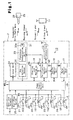
start control system 1 according to a first embodiment of the present invention will now be discussed with reference to Figs. 1 to 3. The enginestart control system 1 is employed in a vehicle including an electronic steering lock mechanism. - Referring to Fig. 1, the engine
start control system 1 includes aportable communicator 11, avehicle controller 12 installed in avehicle 2, and an emergency key mechanism, oremergency key 25. - The
portable communicator 11 is carried by an occupant of thevehicle 2, such as a driver or a passenger, and performs mutual communication with thevehicle controller 12. More specifically, theportable communicator 11 automatically transmits an ID code signal, which includes a predetermined ID code, when receiving a request signal from thevehicle controller 12. The ID code signal is transmitted as a radio wave having a predetermined frequency (e.g., 300 MHz). - The
emergency key 25 is a mechanical key added to theportable communicator 11 and includes atransponder control unit 26. Theemergency key 25 performs mutual communication with thevehicle controller 12. More specifically, theemergency key 25 generates electromotive force when receiving a transponder drive radio wave from thevehicle controller 12. Then, theemergency key 25 uses the electromotive force to generate a response signal including a transponder code. - The
vehicle controller 12 includes atransceiver 13, averification control unit 14, a power supply control unit 15, anengine control unit 16, ameter control unit 17, asteering lock mechanism 18, and an emergencykey holding portion 31. Each of thecontrol units 14 to 17 includes a central processing unit (CPU), a read only memory (ROM), and a random access memory (RAM). Theverification control unit 14 is electrically connected to thetransceiver 13, the power supply control unit 15, theengine control unit 16, and asteering lock mechanism 18. The power supply control unit 15 is electrically connected to theengine control unit 16, themeter control unit 17, thesteering lock mechanism 18, adoor lock detector 19, and a start/stop switch 20. In the preferred embodiment, the start/stop switch 20 is a momentary push button switch. Communication lines (not shown) electrically connects theverification control unit 14, theengine control unit 16, themeter control unit 17, and thesteering lock mechanism 18 to one another. - The
transceiver 13 modulates a request signal output from theverification control unit 14 to a radio wave having a predetermined frequency (e.g., 134 kHz) and transmits the radio wave to predetermined ranges inside the passenger compartment and outside thevehicle 2. When receiving the ID code signal from theportable communicator 11 though an antenna, thetransceiver 13 demodulates the ID code signal to a pulse signal and sends the pulse signal to theverification control unit 14. - The
verification control unit 14 intermittently sends a request signal to thetransceiver 13. When receiving the ID code signal from thetransceiver 13, theverification control unit 14 compares and verifies an ID code included in the ID code signal with a predetermined ID code, which is stored in theverification control unit 14. If the ID codes match when the ID code signal has been transmitted in response to the request signal transmitted outside thevehicle 2, theverification control unit 14 sends a drive signal tc a door lock actuator (not shown) to automatically open a door lock. If the ID codes match when the ID code signal has been transmitted in response to the request signal transmitted inside the vehicle compartment, theverification control unit 14 sends an unlock signal to thesteering lock mechanism 18. When receiving an unlock completion signal from thesteering lock mechanism 18, theverification control unit 14 sends a start enabling signal to the power supply control unit 15 and theengine control unit 16. - When an ID code signal cannot be received in response to the request signal transmitted outside the
vehicle 2 from thetransceiver 13 or when the ID code of the ID code signal received by thetransceiver 13 does not match the ID code of theverification control unit 14, theverification control unit 14 sends a drive signal to the door lock actuator to automatically close the door lock. Further, when an ID code signal cannot be received in response to the request signal transmitted to the inside of the passenger compartment from thetransceiver 13 or when the ID code of the ID code signal received by thetransceiver 13 does not match the ID code of theverification control unit 14, theverification control unit 14 sends a start disabling signal to the power supply control unit 15 and theengine control unit 16. Theverification control unit 14 stops sending the request signal to thetransceiver 13 when receiving an engine drive signal, which indicates that the engine is running, from the power supply control unit 15. In the preferred embodiment, the unlock signal, the unlock completion signal, the start enabling signal, the start disabling signal, and the engine drive signal are binary signals having a predetermined number of bits. Each signal has a unique pattern. When an abnormality such as a short-circuit or a line breakage occurs in the communication lines between theverification control unit 14, thecontrol units 15 and 16, and thesteering lock mechanism 18, the pattern of each binary signal changes. This enables detection of an abnormality with thecontrol units 14 to 16 and thesteering lock mechanism 18. - An accessory (ACC) relay 21, a first ignition (IG1)
relay 22, a second ignition (IG2)relay 23, and a starter (ST)relay 24 respectively have coils L1, L2, L2, and L4. One end of each of the coils L1, L2, L2, and L4 is connected to the power supply control unit 15. More specifically, the power supply control unit 15 is connected to one end of the coils L1 to L4 of the relays 21 to 24 by a switching device, such as a FET (not shown). The other end of each coil L1 to L4 is grounded. Each relay 21 to 24 is activated when an activation signal is output from the power supply control unit 15. In the preferred embodiment, the activation signal generated by the power supply control unit 15 goes high to activate the relays 21 to 24 and goes low to inactivate the relays 21 to 24. - The starting of the engine is enabled when the power supply control unit 15 receives the start enabling signal from the
verification control unit 14. If the start/stop switch 20 is pushed and a push operation signal is received when the starting of the engine is enabled, the power supply control unit 15 sends the activation signal to theIG1 relay 22, theIG2 relay 23, and theST relay 24. The activation signal activates theIG1 relay 22, theIG2 relay 23, and theST relay 24 and closes respective contacts CP2, CP3, and CP4. The contacts CP2 to CP4 each have one end connected to a battery terminal. The other end of the contact CP2 is connected to a power supply terminal of theengine control unit 16 and themeter control unit 17. The other end of the contact CP3 is connected to the power supply terminal of theengine control unit 16. The other end of the contact CP4 is connected to an engine starter (not shown). Thus, theengine control unit 16 is supplied with power through two routes. When the IG1 relay and theIG2 relay 23 are activated, current flows to theengine control unit 16 and themeter control unit 17. When theST relay 24 is activated, the engine starter is activated. When the start/stop switch 20 is pushed, the power supply control unit 15 sends a start signal to theengine control unit 16. In the preferred embodiment, the push operation signal goes high when the start/stop switch 20 is pushed and remains low when the push operation signal is not pushed. - When receiving the start enabling signal from the
verification control unit 14 and the start signal at a high level from the power supply control unit 15, theengine control unit 16 executes fuel injection control and ignition control. In other words, theengine control unit 16 performs fuel injection control and ignition control in accordance with whether the start signal is high or low. Theengine control unit 16 detects whether the engine has been started from an ignition pulse or an alternator output and sends an ignition completion signal to the power supply control unit 15 when determining that the engine has been started. - When the ignition completion signal is received from the
engine control unit 16, the power supply control unit 15 stops providing theST relay 24 with the activation signal to inactivate theST relay 24. The power supply control unit 15 also provides the ACC relay 21 with the activation signal. One end of the contact CP1 for the ACC relay 21 is connected to a battery. The other end is connected to various electric accessory devices. - The
meter control unit 17 controls the operation of meters in the instrument panel of thevehicle 2. When themeter control unit 17 is operated, themeter control unit 17 provides the power supply control unit 15 with a signal representing vehicle information, such as the vehicle velocity. - The
steering lock mechanism 18 includes a lock detection switch and an actuator (neither shown). When the unlock signal is received from theverification control unit 14, thesteering lock mechanism 18 sends a drive signal (unlock drive signal) to the actuator to unlock the steering wheel. The actuator then moves a lock pin (not shown) to disengage the lock pin from a steering shaft. In accordance with a control signal from the power supply control unit 15 and an output signal from a door courtesy switch, thesteering lock mechanism 18 sends a drive signal (lock drive signal) to the actuator to lock the steering wheel when predetermined conditions are satisfied. The actuator then moves the lock pin to engage the lock pin with the steering shaft. The lock detection switch is activated when the lock pin is completely disengaged from the steering shaft. In other words, the luck detection switch detects whether the lock pin is engaged with or disengaged from the steering shaft. When thesteering lock mechanism 18 recognizes by means of the lock detection switch that the leek pin is in the disengaged state, thesteering lock mechanism 18 sends an unlock signal to theverification control unit 14. When thesteering lock mechanism 18 recognizes by means of the lock detection switch that the lock pin is in the engaged state, thesteering lock mechanism 18 sends a lock signal to theverification control unit 14. - The emergency
key seat 31 includes akey detection sensor 32 and atransponder communication unit 33. Thekey detection sensor 32 is electrically connected to the power supply control unit 15, and thetransponder communication unit 33 is connected to theverification control unit 14. - Referring to Figs. 2 and 3, in the passenger compartment, a
glove compartment 3 has akey cylinder 4. Theemergency key 25 is inserted in thekey cylinder 4. Thekey cylinder 4 functions as the emergencykey holding portion 31 and part of a locking mechanism for locking the glove compartment. Thekey deflection sensor 32 and thetransponder communication unit 33 are arranged in an innermost portion of thekey cylinder 4. As shown by the broken lines in Fig. 3, acommunication antenna 33a of thetransponder communication unit 33 is arranged near the innermost portion of thekey cylinder 4. - When the
emergency key 25 is turned in the clockwise direction, theglove compartment 3 is unlocked. When theemergency key 25 is turned in the counterclockwise direction, thekey detection sensor 32 detects the counterclockwise turning and generates a detection signal, which is provided to the power supply control unit 15. When the power supply control unit 15 receives the detection signal, thevehicle controller 12 executes emergency engine start enabling control. In the preferred embodiment, thevehicle controller 12 functions as an emergency engine start enabling device. Thekey cylinder 4 locks theglove compartment 3 at a neutral position (Fig. 3). Thekey cylinder 4 allows the insertion and removal of theemergency key 25 at only the neutral state. When theemergency key 25 is turned from the neutral state, thekey cylinder 4 disables the removal of theemergency key 25. - The emergency engine start enabling control executed when the
emergency key 25 is inserted in thekey cylinder 4 will now be discussed. - Referring to Fig. 1, when the power supply control unit 15 receives the detection signal from the
key detection sensor 32, the power supply control unit 15 sends a transponder drive signal to theverification control unit 14. In response to the transponder drive signal, theverification control unit 14 sends a drive signal to thetransponder communication unit 33. In response to the drive signal, thetransponder communication unit 33 sends a transponder drive radio wave having a predetermined frequency (in the preferred embodiment, 134 kHz) to theemergency key 25 via thecommunication antenna 33a. The transponder drive radio wave is transmitted to a small range around thekey cylinder 4. When the transponder drive radio wave is transmitted in a state in which theemergency key 25 is inserted in thekey cylinder 4, thetransponder control unit 26 of theemergency key 25 receives the transponder drive radio wave. - When receiving the transponder drive radio wave, the
transponder control unit 26 sends a response signal to thetransponder communication unit 33 of thevehicle controller 12. When receiving the response signal, thetransponder communication unit 33 demodulates the response signal to generate a received signal and sends the received signal to theverification control unit 14. Theverification control unit 14 then verifies a transponder code included in the received signal with a transponder code stored beforehand in the verification control unit 14 (transponder verification). When the transponder codes match, theverification control unit 14 sends an unlock request signal to thesteering lock mechanism 18. When thesteering lock mechanism 18 receives an unlock completion signal from thesteering lock mechanism 18, theverification control unit 14 sends a start enabling signal to the power supply control unit 15 and theengine control unit 16. In other words, the same control as when normal communication (smart communication) is established between theportable communicator 11 and thevehicle controller 12 is executed here. Thus, in a state of emergency such as when communication of theportable communicator 11 with thevehicle controller 12 is disabled due to battery drainage, theemergency key 25 is inserted, or deposited in thekey cylinder 4 of theglove compartment 3 to enable the starting of the engine. - The
vehicle controller 12 disables the starting of the engine when theemergency key 25 is turned from the engine start enabling position to the neutral position. If theemergency key 25 is turned from the engine start enabling position to the neutral position when the engine is running, the engine is stopped. - The
door lock detector 19 is connected to the power supply control unit 15. Thedoor lock detector 19 detects whether the door lock of the vehicle has been opened by theemergency key 25 and sends the detection signal to the power supply control unit 15. - Referring to Fig. 3, an
illuminator 34, which is formed by a light-emitting diode (LED) or an electroluminescence (EL) device, is arranged in the vicinity of thekey cylinder 4. Theilluminator 34 is electrically connected to the power supply control unit 15 and is activated and inactivated in accordance with an activation signal from the power supply control unit 15. In the preferred embodiment, theilluminator 34 is generally annular and extends around the periphery of thekey cylinder 4. When activated, theilluminator 34 illuminates thekey cylinder 4. - The power supply control unit 15 sends an activation signal to the
illuminator 34 when a detection signal is received from thedoor lock detector 19 to illuminate theilluminator 34 and notify the driver where theemergency key 25 should be inserted. In this embodiment, the power supply control unit 15 functions as a depositing instruction device. - The preferred embodiment has the advantages described below.
- When the door lock is opened with the
emergency key 25, the power supply control unit 15 illuminates theilluminator 34 in the passenger compartment. Accordingly, even when starting the engine with theemergency key 25, which is seldom used, the driver easily finds the location where theemergency key 25 is to be placed. - When the door lock is opened with the
emergency key 25, there is a high possibility that smart communication cannot be performed between theportable communicator 11 and thevehicle controller 12 due to reasons such as battery drainage of theportable communicator 11. The illumination of theilluminator 34 in only such cases reduces power consumption. - The
key cylinder 4, which locks and unlocks theglove compartment 3, also functions as a holding portion for theemergency key 25. Thus, a separate seat for theemergency key 25 does not have to be provided in the passenger compartment. This reduces the number of components and decreases the production cost. - The
vehicle controller 12 enables the starting of the engine when theemergency key 25 is inserted in thekey cylinder 4 and turned in the counterclockwise direction. In the turned state, theemergency key 25 cannot be removed from thekey cylinder 4. This prevents theemergency key 25 from falling ouL of thekey cylinder 4 when the engine is running. - Subsequent to the depositing and turning of the
emergency key 25 in thekey cylinder 4, thevehicle controller 12 executes emergency engine start enabling control using transponder verification. This maintains a high security level. - The above embodiment may be modified as described below.
- Referring to Fig. 2, a key cylinder 7 for locking and unlocking a
box 6, such as a coin box located in the middle portion of the dashboard 5 may be used as the emergencykey seat 31. Further, a key cylinder 9 for use in a gearshift lock mechanism that locks and unlocks agearshift lever 8 may also be used as the emergencykey seat 31, as shown in Fig. 2. - In the
key cylinder 4 of the embodiment shown in Figs. 1 to 3, thekey cylinder 4 may be fixed so that it cannot be turned. In such a case, the emergency engine start control is performed when theemergency key 25 is inserted in thekey cylinder 4. This would eliminate the need for performing the two operations of inserting theemergency key 25 in thekey cylinder 4 and turning theemergency key 25. The emergency engine start control would be executed just by performing the insertion of theemergency key 25. This improves the operability of the vehicle. - A key holding mechanism (noL shown) that disables the removal of the
emergency key 25 when the engine is running may be added to the emergencykey seat 31. More specifically, a key holding mechanism, which is formed by an actuator such as a solenoid, is arranged in an inner portion of thekey cylinder 4. The power supply control unit 15 controls and activates the key holding mechanism to disable the removal of theemergency key 25 when the engine is running. This ensures that the emergency key is prevented from falling out of thekey cylinder 4 when the engine is running. - In this case, the key holding mechanism may be activated only when the engine is started by transponder communication and not activated when the engine is started by smart communication. This would enable the opening and closing of the glove compartment even when the engine is running as long as the engine is started through smart communication.
- In the embodiment of Figs. 1 to 3, the
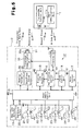
portable communicator 11 and theemergency key 25 may be formed integrally. - A second embodiment of the present invention will now be discussed with reference to Figs. 4 and 5. To avoid redundancy, like or same reference numerals are given to those components that are the same as the corresponding components of the first embodiment. The description centers on parts differing from the first and second embodiments.
- Referring to Fig. 4, in the preferred embodiment, the
communication antenna 33a of thetransponder communication unit 33 is arranged in thebox 6 to transmit a transponder drive radio wave in thebox 6. Thebox 6 is opened and closed by moving thebox 6 in the directions of the arrows. Further, theportable communicator 11 may be deposited in thebox 6. In the preferred embodiment, the emergencykey seat 31 corresponds to thebox 6. - Referring to Fig. 5, the emergency
key seat 31 includes thetransponder communication unit 33, an open/close sensor 35, and anopening mechanism 36. Theopening mechanism 36 includes an actuator, such as a motor, that is activated to automatically open and close the box when predetermined conditions are satisfied. In addition to the automatic opening and closing with theopening mechanism 36, the box may be manually opened. The open/close sensor 35 and theopening mechanism 36 are electrically connected to the power supply control unit 15. - The
portable communicator 11 includes a smart communication unit 11a, which communicates with thetransceiver 13 of thevehicle controller 12, and thetransponder control unit 26. - The
portable communicator 11 includes a mechanical key identical to that of theemergency key 25. The mechanical key is used to open and close the door lock. In the second embodiment, theportable communicator 11 functions as an emergency key mechanism. The smart communication unit 11a is powered by a battery incorporated in theportable communicator 11 and performs smart communication with thetransceiver 13. - When communication is established between the smart communication unit 11a of the
portable communicator 11 and thetransceiver 13, thevehicle controller 12 enables the starting of the engine after unlocking a steering mechanism. - When the power supply control unit 15 receives a detection signal from the
door lock detector 19 indicating that the mechanical key has opened the door lock, the power supply control unit 15 sends a drive signal to theopening mechanism 36 to drive the actuator and open thebox 6. The automatic opening of thebox 6 notifies the driver that theportable communicator 11 is to be placed in thebox 6. In the second embodiment, theopening mechanism 36 functions as a depositing instruction device, and thebox 6 functions as a deposit guide. - When the power supply control unit 15 receives a signal from the open/
close sensor 35 indicating that the box has been closed, the power supply control unit 15 sends a transponder drive signal to theverification control unit 14. When theverification control unit 14 receives the transponder drive signal, theverification control unit 14 sends a drive signal to thetransponder communication unit 33. In response to the drive signal, thetransponder communication unit 33 transmits the transponder drive radio wave from thecommunication antennal 33a. The transponder drive radio wave is transmitted to the space in thebox 6. Thus, theportable communicator 11 receives the transponder drive radio wave as long as theportable communicator 11 is placed in thebox 6. When thetransponder control unit 26 of theportable communicator 11 receives the transponder drive radio wave, thetransponder control unit 26 outputs the response signal. In other words, transponder communication is performed between theportable communicator 11 and thevehicle controller 12. Thevehicle controller 12 enables the starting of the engine when transponder communication is established. Accordingly, in the same manner as the embodiment of Figs. 1 to 3, under an emergency such as when communication of theportable communicator 11 with the vehicle controller is disabled due to battery drainage, the depositing of theportable communicator 11 in thebcx 6 enables the starting of the engine. - The second embodiment has the advantages described below.
- When the
portable communicator 11 is deposited in thebox 6 and transponder communication is performed between theportable communicator 11 and thevehicle controller 12, the starting of the engine is started when transponder communication is established. Thus, if normal communication (smart communication) between theportable communicator 11 and thevehicle controller 12 is disabled such as when battery drainage of theportable communicator 11 occurs, the starting of the engine is enabled by depositing theportable communicator 11 in thebox 6. When the door lock is opened with the mechanical key, the power supply control unit 15 drives theopening mechanism 36 to automatically open the box. This instructs the driver to deposit theportable communicator 11 in thebox 6. Accordingly, even when starting the engine with the emergency key mechanism, which is seldom used, the driver easily finds the location where theportable communicator 11 is to be deposited. - When the door lock is opened with the mechanical key, there is a high possibility that smart communication cannot be performed between the
portable communicator 11 and thevehicle controller 12 due to a reason such as battery drainage of theportable communicator 11. Further, there is a high possibility that the engine is started through transponder communication between theportable communicator 11 and thevehicle controller 12. Thus, the automatic opening of thebox 6 in such a state reduces power consumption. - Small articles such as coins may be kept in the
box 6, which is also used to deposit theportable communicator 11. Thus, a separate space for performing transponder communication is not necessary. This decreases the manufacturing cost of thevehicle 2. Further, thebox 6 is kept closed when the engine is running to prevent theportable communicator 11 from being removed from thebox 6. - The starting of the engine is enabled just by depositing the
portable communicator 11 in thebox 6. This facilitates execution of the emergency engine start enabling control. - It should be apparent to those skilled in the art that the present invention may be embodied in many other specific forms without departing from the spirit or scope of the invention. Particularly, it should be understood that the present invention may be embodied in the following forms.
- In the embodiment of Figs. 4 and 5, the
opening mechanism 36 of the emergencykey holding portion 31 may enable the opening of thebox 6 even when the engine is running. - The emergency
key holding portion 31 does not have to be thebox 6 and may be any type of holder for accommodating articles such as a holder arranged in theglove compartment 3 or in the driver seat side door. - In the embodiment of Figs. 4 and 5, an emergency portable communicator provided with the
transponder control unit 26 may be provided separately from theportable communicator 11. Such emergency portable communicator may be used as the emergency key mechanism. - In the embodiment of Figs. 1 to 3, the
illuminator 34 is illuminated to notify the driver where to insert theemergency key 25. However, the notification may be given by a display message or a voice guidance. More specifically, a message display, such as a liquid crystal panel, may be arranged on theinstrument panel 41 of thevehicle 2, as shown in Fig. 4. Alternatively, a voice guidance device, such as a speaker, may be arranged in the vehicle compartment of thevehicle 2. - The illumination, the notification, the menu display, and the voice guidance may be combined as required to generate the instruction for the driver.
- In the embodiments of Fiqs. 1 to 5, the opening and closing of the door after the mechanical key opens the door lock may trigger the generation of the insert notification for the driver.
- In the embodiments of Figs. 1 to 5, a transponder communication unit may be installed in a door to trigger the generation of a insert notification for the driver when the door lock is opened with the transponder. Accordingly, the notification for the driver may be generated using the opening of the door lock as a trigger instead of relying on the communication between the
portable communicator 11 and thetransceiver 13. - The embodiments of Figs. 1 to 5 are employed in the one-push type engine
start control system 1. However, the present invention may be employed in any engine start control system that has a smart ignition function. - The present examples and embodiments are to be considered as illustrative and not restrictive, and the invention is not to be limited to the details given herein, but is defined by the scope of the appended claims.
Claims (10)
- An engine starting controller for controlling the opening and closing of a door lock and for controlling the starting of an engine for a vehicle (2) in accordance with communication performed with a portable communicator (11) having a communication mechanism and an emergency key mechanism (25), the engine starting controller including an emergency engine start enabling device for enabling the starting of the engine when the emergency key mechanism (25) is placed on an emergency key holding portion (4, 6, 7, 9, 31) arranged in a passenger compartment of the vehicle (2), the engine starting controller (1) being characterized by:a location instruction device (34, 36) for instructing the location of the emergency key mechanism (25) on the emergency key holding portion (31) when the door lock is opened with the emergency key mechanism (25).
- The engine starting controller according to claim 1, characterized in that the location instruction device (34) is located on the emergency key holding portion (31) or in the vicinity of the emergency key holding portion (31), and is illuminated when the door lock is opened with the emergency key mechanism (25).
- The engine starting controller according to claim 1 or 2, characterized in that the location instruction device displays information for instructing the location of the emergency key mechanism (25) or information showing where the emergency key holding portion (31) is located on a display when the door lock is opened with the emergency key mechanism (25) .
- The engine starting controller according to any one of claims 1 to 3, characterized in that the location instruction device announces information for instructing the location of the emergency key mechanism (25) or information showing where the emergency key holding portion (31) is located with a voice when the door lock is opened with the emergency key mechanism (25).
- The engine starting controller according to any one of claims 1 to 4, characterized in that the location instruction device (36) moves the emergency key holding portion (6) from a position disabling location of the emergency key mechanism (25) to a position enabling location of the emergency key mechanism (25) when the door lock is opened with the emergency key mechanism (25) .
- The engine starting controller according to any one of claims 1 to 5, characterized in that the emergency key holding portion (31) is a key cylinder (4, 7) used in a locking mechanism for locking and unlocking a multipurpose container (3, 6) arranged in the passenger compartment, and the emergency key mechanism (25) is a mechanical key inserted in the key cylinder (4, 7 ) .
- The engine starting controller according to any one of claims 1 to 6, characterized in that the emergency key holding portion (31) is a key cylinder (9) for a gearshift locking mechanism that is unlocked by a mechanical key, and the emergency key mechanism (25) is the mechanical key and inserted in the key cylinder (9).
- The engine starting controller according to any one of claims 1 to 7, characterized in that the emergency key mechanism (25) includes a transponder control unit (26) for outputting a response signal with electromotive force generated from a predetermined transponder drive radio wave, the emergency key holding portion (31) is a multipurpose container (6), and the emergency engine start enabling device includes a transponder communication unit (26) for transmitting the transponder drive radio wave in the multipurpose container (6) to perform communication with the transponder control unit (26).
- The engine starting controller according to any one of claims 1 to 8, wherein the location instruction device (34, 36) notifies the location of the emergency key mechanism (25) when a door of the vehicle (2) is closed after a mechanical key opens the door lock of the door.
- The engine starting controller according to claim 1, wherein the location instruction device (34, 36) functions to announce a location of the emergency key holding portion (31).
Applications Claiming Priority (2)
| Application Number | Priority Date | Filing Date | Title |
|---|---|---|---|
| JP2002368117A JP4126224B2 (en) | 2002-12-19 | 2002-12-19 | Engine start control device |
| JP2002368117 | 2002-12-19 |
Publications (3)
| Publication Number | Publication Date |
|---|---|
| EP1431141A2 EP1431141A2 (en) | 2004-06-23 |
| EP1431141A3 EP1431141A3 (en) | 2005-05-18 |
| EP1431141B1 true EP1431141B1 (en) | 2007-12-05 |
Family
ID=32376294
Family Applications (1)
| Application Number | Title | Priority Date | Filing Date |
|---|---|---|---|
| EP20030029224 Expired - Fee Related EP1431141B1 (en) | 2002-12-19 | 2003-12-18 | Engine starting controller for a vehicle |
Country Status (4)
| Country | Link |
|---|---|
| US (1) | US7034658B2 (en) |
| EP (1) | EP1431141B1 (en) |
| JP (1) | JP4126224B2 (en) |
| DE (1) | DE60317871T2 (en) |
Families Citing this family (22)
| Publication number | Priority date | Publication date | Assignee | Title |
|---|---|---|---|---|
| JP4460946B2 (en) * | 2004-05-19 | 2010-05-12 | 株式会社東海理化電機製作所 | Operation control device |
| JP2006321452A (en) * | 2005-05-20 | 2006-11-30 | Yamaha Motor Co Ltd | Vehicle control device for saddle riding type vehicle |
| JP2006321453A (en) * | 2005-05-20 | 2006-11-30 | Yamaha Motor Co Ltd | Vehicle control device for saddle riding type vehicle |
| JP2006321454A (en) * | 2005-05-20 | 2006-11-30 | Yamaha Motor Co Ltd | Vehicle control device for saddle riding type vehicle |
| CN100593487C (en) * | 2005-07-13 | 2010-03-10 | 小松优特力株式会社 | Operation permission control device and machine having the same mounted thereon |
| JP4762639B2 (en) * | 2005-08-09 | 2011-08-31 | 富士重工業株式会社 | Vehicle security system |
| JP4514054B2 (en) * | 2006-03-29 | 2010-07-28 | 古河電気工業株式会社 | Vehicle power supply control device |
| JP2007290651A (en) * | 2006-04-27 | 2007-11-08 | Asahi Denso Co Ltd | Engine starting device |
| JP4881095B2 (en) * | 2006-07-28 | 2012-02-22 | 株式会社東海理化電機製作所 | Key system |
| JP2008074292A (en) * | 2006-09-22 | 2008-04-03 | Mazda Motor Corp | Immobilizer system |
| US7916004B2 (en) * | 2006-12-20 | 2011-03-29 | Dei Headquarters, Inc. | Security system with passive locking bypass |
| DE102007021229A1 (en) * | 2007-05-07 | 2008-11-13 | Bayerische Motoren Werke Aktiengesellschaft | Motor vehicle, has vehicle door, which has door lock by mechanical key and access authorization and driving authorization is checked by electronic authorization system and anti theft alarm system emits warning signal |
| DE102007044871A1 (en) * | 2007-09-20 | 2009-04-09 | Continental Automotive Gmbh | Keyless entry system with emergency function |
| JP5038238B2 (en) * | 2008-06-12 | 2012-10-03 | 株式会社東海理化電機製作所 | Vehicle function restriction system |
| KR100972527B1 (en) * | 2008-06-24 | 2010-07-28 | 우리산업 주식회사 | Smart key system for a vehicle |
| KR20100026162A (en) * | 2008-08-29 | 2010-03-10 | 현대자동차주식회사 | Emergency starting system of a vehicle having button starting system |
| JP5172623B2 (en) * | 2008-11-17 | 2013-03-27 | 株式会社東海理化電機製作所 | Key accommodation device |
| US9133784B2 (en) * | 2011-02-01 | 2015-09-15 | Ford Global Technologies, Llc | Vehicle having key-based performance mode |
| KR101940257B1 (en) * | 2012-07-19 | 2019-01-18 | 현대모비스 주식회사 | Apparatus and Method Utilizing Antenna of Smart Key System for Vehicle |
| JP6957052B2 (en) * | 2017-03-30 | 2021-11-02 | 株式会社ユピテル | Relay system |
| JP2021187389A (en) * | 2020-06-03 | 2021-12-13 | 株式会社東海理化電機製作所 | Enclosure device and system |
| JP2021188446A (en) * | 2020-06-03 | 2021-12-13 | 株式会社東海理化電機製作所 | Enclosure device and system |
Family Cites Families (7)
| Publication number | Priority date | Publication date | Assignee | Title |
|---|---|---|---|---|
| DE19823707A1 (en) * | 1998-01-14 | 1999-12-02 | Bayerische Motoren Werke Ag | Method for operating a vehicle |
| JP3578001B2 (en) * | 1998-07-10 | 2004-10-20 | トヨタ自動車株式会社 | Vehicle security control device |
| JP2001227218A (en) | 2000-02-21 | 2001-08-24 | Omron Corp | Control device |
| JP3536774B2 (en) * | 2000-04-03 | 2004-06-14 | 日産自動車株式会社 | Electronic key device for vehicles |
| JP4377039B2 (en) | 2000-05-12 | 2009-12-02 | 株式会社東海理化電機製作所 | Remote control device for vehicle |
| FR2810776A3 (en) | 2000-06-27 | 2001-12-28 | Valeo Securite Habitacle | Car starter command mechanism having key driving three position rotor with electrical switching central unit transmitting drive signal/authorising starting. |
| FR2839031B1 (en) | 2002-04-30 | 2004-11-26 | Valeo Electronique | SYSTEM FOR CONTROLLING THE ACCESS AND / OR START OF A MOTOR VEHICLE WITH USER ALERTS |
-
2002
- 2002-12-19 JP JP2002368117A patent/JP4126224B2/en not_active Expired - Fee Related
-
2003
- 2003-12-18 EP EP20030029224 patent/EP1431141B1/en not_active Expired - Fee Related
- 2003-12-18 US US10/740,175 patent/US7034658B2/en active Active
- 2003-12-18 DE DE2003617871 patent/DE60317871T2/en not_active Expired - Lifetime
Also Published As
| Publication number | Publication date |
|---|---|
| EP1431141A2 (en) | 2004-06-23 |
| DE60317871T2 (en) | 2008-11-06 |
| US20040217897A1 (en) | 2004-11-04 |
| JP4126224B2 (en) | 2008-07-30 |
| DE60317871D1 (en) | 2008-01-17 |
| EP1431141A3 (en) | 2005-05-18 |
| US7034658B2 (en) | 2006-04-25 |
| JP2004197668A (en) | 2004-07-15 |
Similar Documents
| Publication | Publication Date | Title |
|---|---|---|
| EP1431141B1 (en) | Engine starting controller for a vehicle | |
| EP1659543B1 (en) | Security system and portable device usable therein | |
| JP3571705B2 (en) | Engine start control device | |
| EP1574385B1 (en) | Passive entry system | |
| US7187266B2 (en) | Switch device | |
| US7302817B2 (en) | Apparatus for restricting activation of engine starting system | |
| US7599764B2 (en) | Vehicle remote starting apparatus and method for executing registration process | |
| US6573615B1 (en) | Electronic key system for a vehicle | |
| US7489050B2 (en) | Remote start-up control apparatus, and start-up control apparatus | |
| EP1357003B1 (en) | Vehicle engine starting apparatus | |
| CA2540192C (en) | Remote controlling key for vehicle | |
| US7501714B2 (en) | Engine starting system | |
| US20080224824A1 (en) | Keyless Entry System | |
| JP2007076415A (en) | Vehicle control device | |
| US6900552B2 (en) | System for controlling starting and stopping of engine | |
| JP4094869B2 (en) | Engine start control device | |
| JP2007076416A (en) | Vehicle state monitoring device | |
| JP4001975B2 (en) | Entry control system for vehicles | |
| JP3872078B2 (en) | Moving body starting system | |
| JP3715938B2 (en) | Engine start / stop control system | |
| JP3580530B2 (en) | Smart entry system for vehicles | |
| JP2004108196A (en) | Engine start/stop control system | |
| US6424253B1 (en) | Vehicle protection system and device | |
| JP2005048591A (en) | Engine start / stopping control system | |
| JP4526353B2 (en) | Starter switch |
Legal Events
| Date | Code | Title | Description |
|---|---|---|---|
| PUAI | Public reference made under article 153(3) epc to a published international application that has entered the european phase |
Free format text: ORIGINAL CODE: 0009012 |
|
| AK | Designated contracting states |
Kind code of ref document: A2 Designated state(s): AT BE BG CH CY CZ DE DK EE ES FI FR GB GR HU IE IT LI LU MC NL PT RO SE SI SK TR |
|
| AX | Request for extension of the european patent |
Extension state: AL LT LV MK |
|
| PUAL | Search report despatched |
Free format text: ORIGINAL CODE: 0009013 |
|
| AK | Designated contracting states |
Kind code of ref document: A3 Designated state(s): AT BE BG CH CY CZ DE DK EE ES FI FR GB GR HU IE IT LI LU MC NL PT RO SE SI SK TR |
|
| AX | Request for extension of the european patent |
Extension state: AL LT LV MK |
|
| 17P | Request for examination filed |
Effective date: 20050621 |
|
| AKX | Designation fees paid |
Designated state(s): DE FR GB |
|
| 17Q | First examination report despatched |
Effective date: 20070111 |
|
| GRAP | Despatch of communication of intention to grant a patent |
Free format text: ORIGINAL CODE: EPIDOSNIGR1 |
|
| GRAS | Grant fee paid |
Free format text: ORIGINAL CODE: EPIDOSNIGR3 |
|
| GRAA | (expected) grant |
Free format text: ORIGINAL CODE: 0009210 |
|
| AK | Designated contracting states |
Kind code of ref document: B1 Designated state(s): DE FR GB |
|
| REG | Reference to a national code |
Ref country code: GB Ref legal event code: FG4D |
|
| RIN1 | Information on inventor provided before grant (corrected) |
Inventor name: AOKI, TOSHINORIC/O TOYOTA JIDOSHA KABUSHIKI KAISHA Inventor name: FUNAYAMA, TOMOYUKIC/O TOYOTA JIDOSHA KABUSHIKI KAI Inventor name: HAYASHI, MASAKIC/O KABUSHIKI KAISHA TOKAI RIKA DEN Inventor name: FUKUOKA, YOSHINORIC/O TOYOTA JIDOSHA KABUSHIKI KAI Inventor name: YOSHINO, MASAKIKABUSHIKI KAISHA TOKAI RIKA DENKI S |
|
| REF | Corresponds to: |
Ref document number: 60317871 Country of ref document: DE Date of ref document: 20080117 Kind code of ref document: P |
|
| ET | Fr: translation filed | ||
| PLBE | No opposition filed within time limit |
Free format text: ORIGINAL CODE: 0009261 |
|
| STAA | Information on the status of an ep patent application or granted ep patent |
Free format text: STATUS: NO OPPOSITION FILED WITHIN TIME LIMIT |
|
| 26N | No opposition filed |
Effective date: 20080908 |
|
| REG | Reference to a national code |
Ref country code: DE Ref legal event code: R084 Ref document number: 60317871 Country of ref document: DE |
|
| REG | Reference to a national code |
Ref country code: DE Ref legal event code: R084 Ref document number: 60317871 Country of ref document: DE Effective date: 20121002 |
|
| PGFP | Annual fee paid to national office [announced via postgrant information from national office to epo] |
Ref country code: GB Payment date: 20131218 Year of fee payment: 11 Ref country code: DE Payment date: 20131211 Year of fee payment: 11 |
|
| PGFP | Annual fee paid to national office [announced via postgrant information from national office to epo] |
Ref country code: FR Payment date: 20131209 Year of fee payment: 11 |
|
| REG | Reference to a national code |
Ref country code: DE Ref legal event code: R119 Ref document number: 60317871 Country of ref document: DE |
|
| GBPC | Gb: european patent ceased through non-payment of renewal fee |
Effective date: 20141218 |
|
| REG | Reference to a national code |
Ref country code: FR Ref legal event code: ST Effective date: 20150831 |
|
| PG25 | Lapsed in a contracting state [announced via postgrant information from national office to epo] |
Ref country code: GB Free format text: LAPSE BECAUSE OF NON-PAYMENT OF DUE FEES Effective date: 20141218 Ref country code: DE Free format text: LAPSE BECAUSE OF NON-PAYMENT OF DUE FEES Effective date: 20150701 |
|
| PG25 | Lapsed in a contracting state [announced via postgrant information from national office to epo] |
Ref country code: FR Free format text: LAPSE BECAUSE OF NON-PAYMENT OF DUE FEES Effective date: 20141231 |