EP1431125A1 - Trägersystem für Zusatz-Innenausstattung - Google Patents
Trägersystem für Zusatz-Innenausstattung Download PDFInfo
- Publication number
- EP1431125A1 EP1431125A1 EP03029270A EP03029270A EP1431125A1 EP 1431125 A1 EP1431125 A1 EP 1431125A1 EP 03029270 A EP03029270 A EP 03029270A EP 03029270 A EP03029270 A EP 03029270A EP 1431125 A1 EP1431125 A1 EP 1431125A1
- Authority
- EP
- European Patent Office
- Prior art keywords
- carrier system
- fastening device
- motor vehicle
- connection
- electrical
- Prior art date
- Legal status (The legal status is an assumption and is not a legal conclusion. Google has not performed a legal analysis and makes no representation as to the accuracy of the status listed.)
- Granted
Links
- 238000000034 method Methods 0.000 claims abstract description 10
- 238000010521 absorption reaction Methods 0.000 claims description 20
- 230000008569 process Effects 0.000 claims description 4
- 230000007246 mechanism Effects 0.000 claims description 2
- 230000004888 barrier function Effects 0.000 claims 1
- 230000008901 benefit Effects 0.000 description 13
- 230000006378 damage Effects 0.000 description 4
- 238000013461 design Methods 0.000 description 4
- 238000012549 training Methods 0.000 description 4
- 230000001419 dependent effect Effects 0.000 description 3
- 208000027418 Wounds and injury Diseases 0.000 description 2
- 230000015572 biosynthetic process Effects 0.000 description 2
- 238000011161 development Methods 0.000 description 2
- 230000018109 developmental process Effects 0.000 description 2
- 208000014674 injury Diseases 0.000 description 2
- 238000009434 installation Methods 0.000 description 2
- 238000003860 storage Methods 0.000 description 2
- 238000013459 approach Methods 0.000 description 1
- 230000009286 beneficial effect Effects 0.000 description 1
- 230000005540 biological transmission Effects 0.000 description 1
- 235000019504 cigarettes Nutrition 0.000 description 1
- 238000006073 displacement reaction Methods 0.000 description 1
- 230000002349 favourable effect Effects 0.000 description 1
- 230000006872 improvement Effects 0.000 description 1
- 230000007774 longterm Effects 0.000 description 1
- 230000007257 malfunction Effects 0.000 description 1
- 238000004519 manufacturing process Methods 0.000 description 1
- 239000002184 metal Substances 0.000 description 1
- 238000010327 methods by industry Methods 0.000 description 1
- 238000003825 pressing Methods 0.000 description 1
- 238000000926 separation method Methods 0.000 description 1
- 230000000007 visual effect Effects 0.000 description 1
Images




Classifications
-
- B—PERFORMING OPERATIONS; TRANSPORTING
- B60—VEHICLES IN GENERAL
- B60R—VEHICLES, VEHICLE FITTINGS, OR VEHICLE PARTS, NOT OTHERWISE PROVIDED FOR
- B60R11/00—Arrangements for holding or mounting articles, not otherwise provided for
- B60R11/02—Arrangements for holding or mounting articles, not otherwise provided for for radio sets, television sets, telephones, or the like; Arrangement of controls thereof
-
- B—PERFORMING OPERATIONS; TRANSPORTING
- B60—VEHICLES IN GENERAL
- B60R—VEHICLES, VEHICLE FITTINGS, OR VEHICLE PARTS, NOT OTHERWISE PROVIDED FOR
- B60R11/00—Arrangements for holding or mounting articles, not otherwise provided for
- B60R11/02—Arrangements for holding or mounting articles, not otherwise provided for for radio sets, television sets, telephones, or the like; Arrangement of controls thereof
- B60R11/0229—Arrangements for holding or mounting articles, not otherwise provided for for radio sets, television sets, telephones, or the like; Arrangement of controls thereof for displays, e.g. cathodic tubes
-
- B—PERFORMING OPERATIONS; TRANSPORTING
- B60—VEHICLES IN GENERAL
- B60R—VEHICLES, VEHICLE FITTINGS, OR VEHICLE PARTS, NOT OTHERWISE PROVIDED FOR
- B60R11/00—Arrangements for holding or mounting articles, not otherwise provided for
- B60R11/02—Arrangements for holding or mounting articles, not otherwise provided for for radio sets, television sets, telephones, or the like; Arrangement of controls thereof
- B60R11/0252—Arrangements for holding or mounting articles, not otherwise provided for for radio sets, television sets, telephones, or the like; Arrangement of controls thereof for personal computers, e.g. laptops, notebooks
-
- B—PERFORMING OPERATIONS; TRANSPORTING
- B60—VEHICLES IN GENERAL
- B60R—VEHICLES, VEHICLE FITTINGS, OR VEHICLE PARTS, NOT OTHERWISE PROVIDED FOR
- B60R11/00—Arrangements for holding or mounting articles, not otherwise provided for
- B60R2011/0001—Arrangements for holding or mounting articles, not otherwise provided for characterised by position
- B60R2011/0003—Arrangements for holding or mounting articles, not otherwise provided for characterised by position inside the vehicle
- B60R2011/0012—Seats or parts thereof
-
- B—PERFORMING OPERATIONS; TRANSPORTING
- B60—VEHICLES IN GENERAL
- B60R—VEHICLES, VEHICLE FITTINGS, OR VEHICLE PARTS, NOT OTHERWISE PROVIDED FOR
- B60R11/00—Arrangements for holding or mounting articles, not otherwise provided for
- B60R2011/0096—Theft prevention of articles
-
- B—PERFORMING OPERATIONS; TRANSPORTING
- B60—VEHICLES IN GENERAL
- B60R—VEHICLES, VEHICLE FITTINGS, OR VEHICLE PARTS, NOT OTHERWISE PROVIDED FOR
- B60R11/00—Arrangements for holding or mounting articles, not otherwise provided for
- B60R11/02—Arrangements for holding or mounting articles, not otherwise provided for for radio sets, television sets, telephones, or the like; Arrangement of controls thereof
- B60R2011/0276—Arrangements for holding or mounting articles, not otherwise provided for for radio sets, television sets, telephones, or the like; Arrangement of controls thereof for rear passenger use
Definitions
- the invention relates to a carrier system for mechanical Connection of a replaceable additional interior, especially a center console in a motor vehicle comprising a support frame and fastening devices with anti-unauthorized means To solve.
- Carrier systems usually come everywhere wherever additional equipment with a Base device to be connected.
- Carrier systems come in particular in motor vehicles used where a basic model with different Interior fittings can also be equipped can.
- additional interior fittings distinguished. Firstly, the additional interior be trained for the user that the user can easily assemble and disassemble them leaves. On the other hand, the interior but only with the help of special tools be carried out by authorized workshops.
- the Invention is primarily for operator or user mountable and demountable additional interior thought.
- mountable Additional interior is a child seat, which accordingly Age, weight and / or height of the child varies can be.
- Another example of additional interior fittings are center consoles, which so far are fixed installed and can only be replaced by authorized specialists are.
- General is a generic carrier system for connecting child seats on the back seat in the Rear of a motor vehicle known. These will either on the belt system or by means of other devices connected to the motor vehicle.
- center consoles are located in the Area of the motor vehicle tunnel are known. at the known center consoles have the disadvantage that only to be installed by a specialist with special tools are.
- the invention closes the technical teaching that the substantially L-shaped carrier system in the Area suspended between the outer rear seats is, the carrier system at least one rear fastening device and at least one lower fastening device releasable with the motor vehicle and the additional interior via the upper fastening device is connected to the carrier system.
- a carrier system in the sense of the invention is generally a device for attaching a interchangeable additional part with a base part and in special a fastening device for fastening of interchangeable accessories and additional equipment in one Motor vehicle understood.
- the arrangement of the carrier system takes place above the middle rear seat, so that Accessibility of any arranged on the carrier system Additional interior from lateral is guaranteed.
- the carrier system is preferably L-shaped, so that it fits the seat contour up to the floor area of the Motor vehicle running tunnel optimally encloses and rests on the tunnel, since the electrical / electronic supply of the motor vehicle accessories is accommodated in it is, the carrier system two areas analogous to the two legs of an L's that are together are connected. The two areas be firmly or releasably connected to each other.
- the Carrier system is mounted so that the rear one first Fastening device with those arranged on the motor vehicle Adapter is connected, with the adapter first still allows a pivoting movement of the carrier system and only when it reaches the end position is it crash-proof Connection arises. After swiveling the carrier system the carrier system lies when the end position is reached with the lower fastening device on the tunnel system on.
- the lower fastening device is there variably configurable.
- the lower fastening device is preferred as part of a multi-part fastening system trained, a part of which with the invention Carrier system is connectable and the other Part can be connected to the tunnel system of the motor vehicle is. In this way, the carrier system is easy assemble by hand.
- This solution therefore has the advantage that due to the floating arrangement of the carrier system practically no wear occurs. Furthermore, the carrier system due to the formation of the rear and the lower fastening device easily by the user assemble and disassemble. The additional interior is easy to assemble by the user and disassemble.
- An advantageous embodiment of the invention provides that the carrier system over the middle seat is arranged. So because of the L-shaped Design of the carrier system saves space Arrange floating above the middle rear seat without that a user before assembling the middle rear seat must take out. As a result, the invention Carrier system a clear comfort advantage and the user don't have to worry about where to find a removable Can accommodate seat.
- the carrier system is an electrical / electronic Interface for connecting additional interior equipment to the on-board electronics and / or on-board electronics of the motor vehicle.
- additional electrically operated and / or electronic Install additional interior equipment without on mobile Energy supply which is only for a limited period the energy supply enables to be dependent.
- So can be, for example, notebooks, DVD players or others Electrical appliances comfortably in the rear of the motor vehicle to install.
- Motor vehicles do offer additional ones Electrical supplies in the fund of a motor vehicle, however, these are mostly in the form of 12 V connections that Cigarette lighter-shaped and ergonomic Arranged positions difficult to reach or the overall appearance of the vehicle interior is negative influence.
- the carrier system according to the invention also offers the advantage that the electrical / electronic Interface an upper and a lower connection area has, the upper area for electrical / electronic Connection of the interface with a Additional interior is designed and the lower Area for ground-level electrical / electronic Connected with the on-board electronics / on-board electronics is.
- the electrical supply can be in one ergonomically unfavorable, but the visual appearance of the motor vehicle interior not negatively influencing Position can be arranged because of the carrier system an electrical / electronic interface is provided, which is in an ergonomically favorable position is arranged for the user.
- Carrier system preferably a device with which the carrier system with a simple handle both one mechanical connection as well as an electrical / electronic Connection to the motor vehicle realized.
- connection of the lower connection area with a upper connection area realized.
- the additional interior can be directly in the upper connection area the carrier system can be connected without cables in the Interior of the motor vehicle lying loosely around. Not least the top cover of the carrier system ensures that that's the electrical / electronic interface too optically not the overall impression of the vehicle interior negatively affected
- the carrier system optimally to the conditions in the interior of the Motor vehicle adapted.
- the L-shaped support system is as lying "L" arranged in the motor vehicle such that the shorter part of the carrier system essentially in Points towards the vehicle floor and the longer part of the Carrier system essentially parallel to the seat of the Rear seats is aligned.
- both parts of the carrier system are the same length or also have any other size ratio to each other.
- the size ratio listed above has changed turned out to be optimal because the carrier system thus making the best possible use of the vehicle interior.
- the top cover has one carrier system according to the invention an edge region and a Interior area, with at least the edge area as Support surface is formed in which the upper fastening device for mechanical attachment of additional interior fittings formed on the carrier system is.
- the carrier system is designed so that it for the most diverse additional interior fittings are suitable, is in addition to an upper fastening device Compatible with any type of additional equipment necessary.
- a contact surface fulfills this requirement with multiple areas, especially one Inside and a border area, the areas on levels different heights can be arranged, whereby several support options can be realized.
- the sufficient space to design the surface for example at different levels, provides and which due to the large contact area has a low mechanical It is advantageous to load the bearing surface the upper fastening device, which in the Support surface is arranged on the longer part of the Carrier system to accommodate.
- the rear fastening device in an area of the longer one Part of the carrier system is arranged, which in Arranged essentially adjacent to the backrest of the rear seats is.
- the upper fastening device than at least one recess in the Support surface for the guided inclusion of the additional interior is designed to correspond to the recess Connection units of the additional interior take.
- the recesses do not have to be all be shaped in the same way. So can the recesses be shaped differently to avoid the risk of to rule out faulty assembly.
- Training the upper fastening device is as a recess Particularly suitable because it makes the type of Connection unit can be varied within certain limits can to achieve an optimal connection.
- the recess the support surface is designed as a slot, which is formed wider in a first area, and is made narrower in a second area by one Additional interior fittings by means of vertical mounting and move horizontally. Based on these Forming the slots with multiple areas can be specify the type of assembly, thereby providing security against incorrect assembly is given. In addition, due to the special shape of the slots prevents additional equipment unsuitable for a motor vehicle type, immediately during assembly due to incompatible connection devices can be assembled. By execution the recess as a slot is also a combined one Assembly from vertical and horizontal movement necessary, whereby the combination of additional interior and Carrier system additional connection stop is given and unwanted disassembly can also be avoided can.
- the upper fastening device at least one, preferably two and particularly preferably four recesses to accommodate additional interior fittings having.
- Security or the reliability of the connection. Should a crash occur in one of the many top Fasteners can fail, their function through the remaining functional top fasteners be compensated.
- Moreover can be used with a higher number of upper fastening devices easier positioning and Align the additional interior.
- Another embodiment of the invention stipulates that the inner area of the contact surface as Recess is formed, which is an elevated Has interface area in which an electrical / electronic interface to the electrical and / or electronic connection of the additional interior with the on-board electronics and / or on-board electronics is designed. Due to the arrangement of the interface indoors creates protection for the mostly more sensitive electrical / electronic Connection between additional equipment and carrier system. With additional equipment installed the interface thus completely from the carrier system and the additional interior, which on the one hand the susceptibility to failure and possible damage to the Interface are avoided and on the other hand interference and damage through the interface can be avoided.
- the interface is designed so that a Connection of carrier system and additional equipment only can be carried out if installed correctly. So offers the arrangement of the interface an additional safety function.
- the arrangement of the interface within a recessed interior offers, among other things, the The advantage that the carrier system is not so bulky and the interface, especially when the additional equipment is not installed is better protected.
- the through the recessed interior and the raised edge area and / or defined the increased interface area Heel with a corresponding locking device of the additional interior can cooperate and thus as Security unit or security device against unauthorized Remove the additional interior from that Carrier system acts. This is how it can be done trained paragraph excellent for further, on the additional equipment use the ordered safety device, by the safety device of the additional equipment and the paragraph work together. This will make the Combination of carrier system and additional equipment connected more securely and reliably.
- the carrier system provides that the lower fastening device on the floor area of a motor vehicle in the footwell of the Motor vehicle can be placed and with this over a Lever mechanism is connectable, so that a mechanical Connection and / or a connection to the electrical system and / or on-board electronics.
- the lower fastening device can be made in one piece as an integral part of the carrier system be formed, or in several parts than with Carrier system and the lower fastening device connectable to the tunnel system be trained.
- the lower fastening device is preferably designed so that with lever actuation both mechanical Connection as well as an electrical / electronic contact of the carrier system with the tunnel electrics / electronics. With such a lower one Fastening device is easy to use Carrier system in particular a simple assembly with a few Actions by the user possible.
- the lower one Fastening device has a securing device, an unauthorized release of the carrier system prevented.
- the safety device is preferably actuated trained to be an accidental Operation is excluded.
- the safety device particularly prevents loosening of the carrier system with connected additional interior.
- the safety device can display what information about the status of the lock there. This ad can, for example, also on the on-board electronics on instrument panels be displayed inside the vehicle. It is also conceivable that this via the on-board electronics Safety device actuated, that is lockable or can be unlocked.
- the securing device as a resilient element with an as Lock shaped survey is formed.
- This training allows a highly efficient but simply constructed Safety device in the smallest space in the train the front cover. It can also be two or several safety devices can be formed, whereby an additional security against unauthorized or unintentional loosening is guaranteed.
- the safety devices can each be different be trained. So is a combination of a resilient Elementes and any other embodiment conceivable.
- An advantageous embodiment of the invention stipulates that the rear fastening device at least two storage areas for connection with two holding devices has, the rear fastening device is designed so that in a horizontal position of the carrier system, the rear fastening device is connected to the motor vehicle, and that at inclined position of the carrier system to the seat Carrier system is detachable.
- the carrier system is preferably designed such that that the rear fastening device with the Carrier frame is connected. This way realize a stable connection.
- the energy required for Example released on impact is thereby optimal due to the most stable components of the carrier system derived.
- the rear Fastening device via an adapter which with the motor vehicle is connected, is connectable. Not in each motor vehicle are on the side of the center seat in Bolts arranged in the rear for fastening the rear fastening device available. To nevertheless the carrier system in motor vehicles already available on the market To put on, it is advantageous that the rear Fastening device via an easily retrofittable Adapter can be connected to the motor vehicle.
- the adapter preferably has at least one Profile frame, at least one tab and at least one Connector for connecting the adapter to the Motor vehicle, in particular with the body of the motor vehicle, on.
- the profile frame ensures this structure for the necessary stability. Via the connector becomes a secure connection between adapter and motor vehicle realized.
- the tab serves as a safe and reliably connecting the rear fastening device with the adapter.
- the connector is advantageous releasable via a screw connection with the motor vehicle connectable. So the adapter can be exchanged as desired and in the event of wear, for example after a lighter crash, replace easily. moreover it is advantageous that, alternatively, the connector non-detachable with, for example, a forming connection the motor vehicle is connectable. That way realize a permanent connection of the adapter, which with appropriate design of the components of the Adapter is designed for long-term use.
- This indissoluble connection is special Embodiment designed so that the connector permanently welded to the motor vehicle is.
- This connection can be used on the carrier system Forces acting on the motor vehicle without problems transmitted, the connection being reliable and simple is to be produced.
- the rear fastening device is one embodiment of the invention designed so that with the carrier system installed, in the between a lower area of a backrest padding and a rear area of a corresponding upholstery Seat shaped gap protrudes. So is next the better appearance also ensures that any metal parts, the additional ones in the event of a crash, for example Cause injury to vehicle occupants could be separated from the interior by the padding are and so a better occupant protection arises.
- the support frame is integrated into the support frame Energy absorption device comprising a profiled sheet with a deformable area, the rear Fastening device on the energy absorption device is arranged.
- the carrier frame of the carrier system due to the limited availability Installation space cannot be dimensioned to any size, that he can handle all occurring amounts of energy without failure can derive, it is an improvement of the invention Measure that an additional energy absorption frame in the carrier system, favorably in the carrier frame is integrated.
- the energy absorption device is there trained so that when a certain amount of energy acting on the carrier system the amount of energy absorbed by plastic deformation.
- the deformable area the energy absorption device has a slot with a Recess which is wider than the slot has, at the slot end, being in the recess is designed to receive a bolt.
- the slot can be the direction in which the energy absorption act should be predetermined. That way the energy is specifically derived without it being, for example to unplanned splinters, which one additional hazard potential for the motor vehicle occupants form.
- Another advantage is achieved by that the energy absorption device with the support frame is connected via a bolt connection, the Bolts arranged in the larger recess of the slot is that in the event of a crash the bolt cuts the slot expands and deforms and thus the energy of the crash absorbed.
- This arrangement offers the advantage that this Energy absorption device easy to implement is and is easy to assemble with the support frame.
- Another embodiment of the invention provides that the electrical / electronic interface electrical lines for connecting the electrical Interface with the on-board electronics and / or on-board electronics having.
- the Interface at any position on the carrier system arrange without being close to the tunnel, which surrounds the on-board electrical system / electronics, necessary is. This allows electrical / electronic connections ergonomic for the passenger inside the Arrange the carrier system.
- At least one cover with the Seat, the backrest and the tunnel of the motor vehicle concludes. Since the carrier system hovers over the middle rear seat would be arranged without one cover according to the invention also optically unsightly Form a gap between the support system and the upholstery. By this gap can inadvertently parts in the upholstery penetrate and cause malfunctions. In addition, could vehicle occupants, for example, fingers in it Pinch the gap. Therefore, the covers offer an advantageous one Protection.
- a second task is to have a process ready to provide the user of motor vehicles it enables a carrier system according to the invention simple and in a few simple steps and without special tools to connect with a motor vehicle.
- This task is based on a process for connecting a carrier system according to the preamble of claim 26 in conjunction with the characterizing Features resolved. Advantageous further training the invention are specified in the dependent claims.
- the invention closes the process engineering Teach that the procedure is crash-safe Attachment of a carrier system with a motor vehicle and connecting the carrier system to an existing one Electrics / electronics system includes the following steps: Position a rear fastener and connecting with an adapter and pressing one lower actuator for connection to a Connection part, in particular with a motor vehicle, preferred with a tunnel system of a motor vehicle.
- the positioning a rear fastening device and connecting with an adapter involves the following steps: hang up the rear fastening device in an angular orientation to one through a seat of a rear seat formed, essentially horizontal level on a first fastening unit of an adapter, moving the rear fastening device via the first fastening unit up to a first stop and swiveling the rear fastener into one essentially horizontal orientation up to a second Attack.
- the user can use the two stops on the one hand reduce the force to be used by can place the carrier system on the fastening unit and the carrier system along this fastening unit can move and secondly that by the attacks easy operation without difficult positioning can be done.
- the actuation an actuator for attaching a lower one Fastening device comprising the steps: mechanical Connection and electrical / electronic connection to a tunnel system of a motor vehicle, the mechanical and electrical / electronic connection can be realized with a single actuation process.
- the user does not have to face a difficult predicament for safe and reliable assembly of the carrier system but can be comfortable and ergonomic with one Handle an electrical / electronic at the same time Establish connection as well as a mechanical connection.
- Fig. 1 shows a perspective view a carrier system 1 according to the invention, which has three fastening devices, an upper fastening device 2 for attaching an additional interior and two Fasteners, a lower one (not shown here) and a rear fastening device 3 for Attachment of the carrier system 1 with a basic model, in the present case for attachment with a Motor vehicle.
- the carrier system 1 has four upper fastening devices 2 on that as slots in the shaped upper bearing surface 4 of the top cover 5 are, so an additional interior with accordingly trained, corresponding fastening devices, that can engage in the slots with these can work together.
- the slots have one wider and a narrower range.
- the wider one The area is used for essentially vertical placement the additional interior, which is then essentially a vertical displacement along the contact surface 4 is connected to the carrier system 1.
- the contact surface 4 has a recessed inner region 6 which together with one arranged in the inner region 6 elevated electrical / electronic interface 7 and the Support surface 4 forms a paragraph, which with a Interlocking device of the additional interior interacts.
- the electrical / electronic - in short electr. - Interface 7 of the essentially L-shaped Carrier system 1 is used for electr. Supplying the additional interior.
- the carrier system 1 1 a front cover 8, which at the same time the carrier system 1 limited to the environment and thereby provides protection and along with the top cover determines the appearance of the entire carrier system 1.
- the rear fastening device 3 comprises two in assembled state protruding into the seat bite of the motor vehicle Institutions, which together with at least one adapter arranged on the motor vehicle (not here shown) interact and a mechanical connection realize.
- the connection is so reliable that the carrier system 1 a motor vehicle crash withstands according to the applicable regulations.
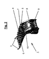
- Fig. 2 shows another variant of an inventive Carrier system 1 in another perspective View, which is shown in Fig. 2 Variant solely through the differently shaped rear fastening device 2 differs.
- the front one Cover 8 has two slot-shaped recesses on which is arranged for guiding a in the recesses Control element (not shown) are used.
- This Control element is through a safety device 9, which is a resilient element with a nose Increase includes against unauthorized loosening of the carrier system 1 secured.
- the safety device also includes an element through the opening 10 can be performed, and so only an opening when dismantled Additional interior equipment allows.
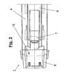
- FIG. 3 is a detail of a top view shown on a carrier system 1 according to the invention.
- the two covers 5, 8 can be clearly seen here.
- the opening 10 can also be closed Detect guidance of a safety device, which in the front cover 8, which is seen in the left Area is shown, is formed.
- the one on the right Top cover 5 shown in the illustration according to the invention has a storage surface 4 in which a upper fastening device 2 in the form of four Slits is formed, which is a wider and one have narrower range.
- the bearing surface 4 surrounds a recessed inner region 6, which an electrical Interface 7 has.
- the shown in Fig. 3 Covers 5, 8 are preferably made of plastic manufactured.
- Fig. 4 is the carrier system shown in Fig. 3 1 shown in front view. It is clear the trained in the top cover 5 increased electr. Interface 7 to recognize which one connector for connection one equipped with a corresponding plug Has additional interior.
- the front cover 8 is the opening 10 for Management of a safety device (not shown) recognizable.
- this actuator is designed as a lever 11.
- the lower fastening device 12 can be lever 11 actuate. This fastening device 12 provides at the same time a mechanical connection to the motor vehicle and a mechanical connection to the on-board electrical system / electronics forth.
- Fig. 5 shows a longitudinal section through an inventive Carrier system 1 in side view.
- the arrangement is arranged in a space-optimized manner is and thus requires little installation space, so that a compact carrier system 1 can be realized.
- Fig. 6 shows a perspective view a support frame 13 with an energy absorption device 14 is connected to a rear fastening device 3 is arranged.
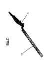
- the energy absorption device 14, which is shown larger in Fig. 7 is via a bolt connection, which is the end area the slot of the energy absorption device 14 penetrates, connected to the support frame 13.
- a sufficient amount of energy shifts the support frame 13 relative to the energy absorption device 14 and deforms them plastically, creating energy is absorbed.
- the energy absorption device 14 after Fig. 7 is designed as a U-shaped profile sheet, which has a slot, each at both ends has a round opening for receiving a bolt or a similar body is formed.
- a rear fastening device 3 On one The end of the profile sheet is a rear fastening device 3 arranged and inseparable from the profiled sheet connected. This arrangement is made with the support frame (not shown here) and forms one Part of the carrier system.
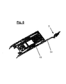
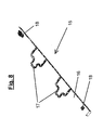
- the adapter 15 shows a perspective illustration one belonging to a carrier system according to the invention Adapter 15.
- the adapter 15 consists of a Square profile tube formed profile frame 16 which two tabs 17 for connection to a rear Fastening device are arranged. It also points out Profile tube two connectors 18 for mechanical Connection of the adapter 15 to the motor vehicle.
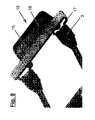
- a Detachable connection of an adapter 15 to the motor vehicle represents Fig. 9.
- the cutout comprises a rear fastening device 3 and an adapter 15 which are connected to each other.
- the adapter 15 comprises a square tube Profile frame 16, two tabs 17 attached to the square tube are arranged and a connecting piece 18, which is designed as a sheet that on the square tube is arranged and two openings for a screw connection with the body of the motor vehicle.
- Fig. 10 is the assembly of the rear attachment 3 of the carrier system shown in three steps, each step is shown in a sub-figure.
- the uppermost first sub-figure shows the fastening device 3 in the unmounted position.
- the fastening device 3 becomes angled to the seat at first lower of two bolts one with the motor vehicle or the adapter 15 connected to the seat.
- one second step shown in the middle second sub-figure the rear fastening device 3 in practically the same position as in the first sub-figure over the first lower bolt between the first and second bolt moved until the rear fastening device 3 with a specially trained stop abuts the first lower bolt.
Landscapes
- Engineering & Computer Science (AREA)
- Mechanical Engineering (AREA)
- Seats For Vehicles (AREA)
- Fittings On The Vehicle Exterior For Carrying Loads, And Devices For Holding Or Mounting Articles (AREA)
Abstract
Description
- Fig. 1
- eine perspektivische Ansicht eines erfindungsgemäßen Trägersystems;
- Fig. 2
- eine perspektivische Ansicht eines zweiten erfindungsgemäßen Trägersystems;
- Fig. 3
- ein Ausschnitt einer Draufsicht auf ein erfindungsgemäßes Trägersystem;
- Fig. 4
- eine Vorderansicht eines erfindungsgemäßen Trägersystems;
- Fig. 5
- einen Längsschnitt eines erfindungsgemäßen Trägersystems in Seitenansicht;
- Fig. 6
- eine perspektivische Ansicht eines Trägerrahmens mit Energieabsorptionseinrichtung und hinterer Befestigungsvorrichtung;
- Fig. 7
- eine perspektivische Ansicht einer Energieabsorptionseinrichtung eines erfindungsgemäßen Trägersystems;
- Fig. 8
- eine perspektivische Ansicht eines Adapters eines erfindungsgemäßen Trägersystems;
- Fig. 9
- einen Ausschnitt in perspektivischer Ansicht eines erfindungsgemäßen Trägersystems und
- Fig. 10
- die Montage der hinteren Befestigung des Trägersystems an einem Adapter in Seitenansicht.
- 1
- Trägersystem
- 2
- obere Befestigungsvorrichtung
- 3
- hintere Befestigungsvorrichtung
- 4
- Auflagefläche
- 5
- obere Abdeckung
- 6
- Innenbereich
- 7
- elektrische/elektronische Schnittstelle
- 8
- vordere Abdeckung
- 9
- Sicherheitsvorrichtung
- 10
- Öffnung
- 11
- Hebel
- 12
- untere Befestigungsvorrichtung
- 13
- Trägerrahmen
- 14
- Energieabsorptionseinrichtung
- 15
- Adapter
- 16
- Profilrahmen
- 17
- Lasche
- 18
- Verbindungsstück
Claims (37)
- Trägersystem (1) zur mechanischen Verbindung einer austauschbaren Zusatz-Innenausstattung, insbesondere einer Mittelkonsole, zum Einsatz in einem Kraftfahrzeug umfassend einen Trägerrahmen (13) und Befestigungsvorrichtungen (2,3) mit Mitteln gegen unautorisiertes Lösen, dadurch gekennzeichnet, dass das im Wesentlichen L-förmige Trägersystem (1) im Bereich zwischen den äußeren Fondsitzen schwebend angeordnet ist, wobei das Trägersystem (1) mindestens über eine hintere Befestigungsvorrichtung (3) und mindestens über eine untere Befestigungsvorrichtung (12) lösbar mit dem Kraftfahrzeug und die Zusatz-Innenausstattung über die obere Befestigungsvorrichtung (2) mit dem Trägersystem (1) verbunden ist.
- Trägersystem (1) nach Anspruch 1, dadurch gekennzeichnet, dass das Trägersystem (1) über der mittleren Sitzfläche angeordnet ist.
- Trägersystem (1) nach Anspruch 1 oder 2, dadurch gekennzeichnet, dass das Trägersystem (1) anstelle des mittleren Sitzes angeordnet ist.
- Trägersystem (1) nach einem der vorherigen Ansprüche, dadurch gekennzeichnet, dass das Trägersystem eine elektrische/elektronische Schnittstelle (7) zum Anschluss einer Zusatz-Innenausstattung an die Bordelektrik und/oder Bordelektronik des Kraftfahrzeugs aufweist.
- Trägersystem (1) nach einem der vorherigen Ansprüche, dadurch gekennzeichnet, dass die elektrische/elektronische Schnittstelle (7) einen oberen und einen unteren Anschlussbereich aufweist, wobei der obere Bereich zur elektrischen/elektronische Verbindung der Schnittstelle (7) mit einer Zusatz-Innenausstattung ausgebildet ist und der untere Bereich zur bodennahen elektrischen/elektronischen Verbindung mit der Bordelektrik/Bordelektronik ausgebildet ist.
- Trägersystem (1) nach einem der vorherigen Ansprüche, dadurch gekennzeichnet, dass das L-förmige Trägersystem (1) als liegendes "L" so in dem Kraftfahrzeug angeordnet ist, dass der kürzere Teil des Trägersystems (1) im Wesentlichen in Richtung Fahrzeugboden weist und der längere Teil des Trägersystems (1) im Wesentlichen parallel zur Sitzfläche der Fondssitze ausgerichtet ist.
- Trägersystem (1) nach einem der vorherigen Ansprüche, dadurch gekennzeichnet, dass eine obere Abdeckung (5) zum Schutz und zur Begrenzung des Trägersystems (1) einen Randbereich und einen Innenbereich (6) aufweist, wobei zumindest der Randbereich als Auflagefläche (4) ausgebildet ist, in der die obere Befestigungsvorrichtung (2) zur mechanischen Befestigung einer Zusatz-Innenausstattung an dem Trägersystem (1) ausgebildet ist.
- Trägersystem (1) nach einem der vorherigen Ansprüche, dadurch gekennzeichnet, dass die obere Befestigungsvorrichtung (2) auf einer Oberfläche des längeren Teils des Trägersystems (1) angeordnet ist, welche im Wesentlichen in Richtung Fahrzeugdach gerichtet ist.
- Trägersystem (1) nach einem der vorherigen Ansprüche, dadurch gekennzeichnet, dass die untere Befestigungsvorrichtung (12) in einem Bereich des kürzeren Teils des Trägersystems (1) angeordnet ist, welcher im Wesentlichen benachbart zum Fahrzeugboden angeordnet ist.
- Trägersystem (1) nach einem der vorherigen Ansprüche, dadurch gekennzeichnet, dass die hintere Befestigungsvorrichtung (3) in einem Bereich des längeren Teils des Trägersystems (1) angeordnet ist, welcher im Wesentlichen benachbart zur Rückenlehne der Fondsitze angeordnet ist.
- Trägersystem (1) nach einem der vorherigen Ansprüche, dadurch gekennzeichnet, dass die obere Befestigungsvorrichtung (2) als mindestens eine Ausnehmung in der Auflagefläche (4) zur geführten Aufnahme der Zusatz-Innenausstattung ausgebildet ist, um mit der Ausnehmung korrespondierende Anbindungseinheiten der Zusatz-Innenausstattung aufzunehmen.
- Trägersystem (1) nach einem der vorherigen Ansprüche, dadurch gekennzeichnet, dass die Ausnehmung der Auflagefläche (4) als Schlitz ausgebildete ist, die in einem ersten Bereich breiter ausgebildet ist, und in einem zweiten Bereich schmaler ausgebildet ist, um eine Zusatz-Innenausstattung mittels vertikalem Aufsetzen und horizontalem Verschieben aufzunehmen.
- Trägersystem (1) nach Anspruch 8 oder 12, dadurch gekennzeichnet, dass die obere Befestigungsvorrichtung (2) mindestens eine, bevorzugt zwei und besonders bevorzugt vier Ausnehmungen zur Aufnahme einer Zusatz-Innenausstattung aufweist.
- Trägersystem (1) nach Anspruch 7, dadurch gekennzeichnet, dass der Innenbereich (6) der oberen Abdeckung (5) als Vertiefung ausgebildet ist, welche einen erhöhten Schnittstellenbereich aufweist, in dem eine elektrische/elektronische Schnittstelle (7) zur elektrischen und/oder elektronischen Verbindung der Zusatz-Innenausstattung mit der Bordelektrik und/oder Bordelektronik ausgebildet ist.
- Trägersystem (1) nach einem der vorherigen Ansprüche 7 bis 14, dadurch gekennzeichnet, dass der durch den vertieften Innenbereich (6) und dem erhöhten Randbereich und/oder den erhöhten Schnittstellenbereich definierte Absatz mit einer entsprechenden Rastvorrichtung der Zusatz-Innenausstattung zusammenwirkt und als Sicherungseinheit gegen unautorisiertes Abnehmen der Zusatz-Innenausstattung von dem Trägersystem (1) fungiert.
- Trägersystem (1) nach Anspruch 1, dadurch gekennzeichnet, dass die untere Befestigungsvorrichtung (3) auf den Bodenbereich eines Kraftfahrzeugs im Fußraum des Kraftfahrzeugfonds aufsetzbar ist und mit diesem über einen Hebelmechanismus verbindbar ist, so dass eine mechanische Verbindung und/oder eine Verbindung mit der Bordelektrik und/oder Bordelektronik zustande kommt.
- Trägersystem (1) nach Anspruch 16, dadurch gekennzeichnet, dass der Bodenbereich eines Kraftfahrzeugs, auf dem die untere Befestigungsvorrichtung (3) aufsetzbar ist, ein Tunnelsystem eines Kraftfahrzeugs ist.
- Trägersystem (1) nach einem der vorherigen Ansprüche, dadurch gekennzeichnet, dass die untere Befestigungsvorrichtung eine Sicherungsvorrichtung (9) aufweist, die ein unautorisiertes Lösen des Trägersystems (1) verhindert.
- Trägersystem (1) nach Anspruch 14, dadurch gekennzeichnet, dass die Sicherungsvorrichtung (9) ein federndes Element umfasst, welches mit einer als Sperre ausgeformten Erhebung ausgebildet ist.
- Trägersystem (1) nach Anspruch 1, dadurch gekennzeichnet, dass die hintere Befestigungsvorrichtung (3) über eine Einhakvorrichtung nach Art einer Schlossfalle mit seitlich an dem mittleren Fondsitz befindliche Bolzen verbindbar ist.
- Trägersystem (1) nach Anspruch 16, dadurch gekennzeichnet, dass die hintere Befestigungsvorrichtung (3) mindestens zwei Lagerflächen zur Verbindung mit zwei Haltevorrichtungen aufweist, wobei die hintere Befestigungsvorrichtung (3) so ausgebildet ist, dass bei waagerechter Position des Trägersystems (1) die hintere Befestigungsvorrichtung (3) mit dem Kraftfahrzeug verbunden ist, und dass bei geneigter Position des Trägersystems (1) zur Sitzfläche das Trägersystem (1) lösbar ist.
- Trägersystem (1) nach Anspruch 16 oder 17, dadurch gekennzeichnet, dass die hintere Befestigungsvorrichtung (3) mit dem Trägerrahmen (13) verbunden ist.
- Trägersystem (1) nach einem der vorherigen Ansprüche 16 bis 18, dadurch gekennzeichnet, dass die hintere Befestigungsvorrichtung (3) über einen Adapter (15), welche mit dem Kraftfahrzeug verbunden ist, lösbar verbindbar ist.
- Trägersystem (1) nach einem der vorherigen Ansprüche 16 bis 19, dadurch gekennzeichnet, dass der Adapter (15) mit der hinteren Befestigungsvorrichtung (3) nach Art eines Schnappschlosssystems ausbildet ist.
- Trägersystem (1) nach Anspruch 19 oder 20, dadurch gekennzeichnet, dass der Adapter (15) mindestens einen Profilrahmen (16), mindestens eine Lasche (17) und mindestens ein Verbindungsstück (18) zur Verbindung des Adapters (15) mit dem Kraftfahrzeug insbesondere mit der Karosserie des Kraftfahrzeugs aufweist.
- Trägersystem (1) nach Anspruch 21, dadurch gekennzeichnet, dass das Verbindungsstück (18) lösbar über eine Schraubenverbindung mit dem Kraftfahrzeug verbindbar ist.
- Trägersystem (1) nach Anspruch 21 oder 22, dadurch gekennzeichnet, dass das Verbindungsstück (18) unlösbar über eine Umformverbindung mit dem Kraftfahrzeug verbindbar ist.
- Trägersystem (1) nach einem der Ansprüche 21 bis 23, dadurch gekennzeichnet, dass das Verbindungsstück (18) unlösbar mit dem Kraftfahrzeug verschweißt ist.
- Trägersystem (1) nach einem der vorherigen Ansprüche 16 bis 24, dadurch gekennzeichnet, dass die hintere Befestigungsvorrichtung (3) bei montiertem Trägersystem (1) in den zwischen einem unteren Bereich einer Polsterung einer Rückenlehne und einem hinteren Bereich einer Polsterung einer korrespondierenden Sitzfläche geformten Spalt ragt.
- Trägersystem (1) nach Anspruch 1, dadurch gekennzeichnet, dass der Trägerrahmen (13) eine in den Trägerrahmen (13) integrierte Energieabsorptionseinrichtung (14) umfassend einen Profilrahmen mit einem deformierbaren Bereich aufweist, wobei die hintere Befestigungsvorrichtung (3) an der Energieabsorptionseinrichtung (14) angeordnet ist.
- Trägersystem (1) nach Anspruch 26, dadurch gekennzeichnet, dass der deformierbare Bereich der Energieabsorptionseinrichtung (14) einen Schlitz mit einer größeren Ausnehmung am Schlitzende aufweist, wobei die größere Ausnehmung zur Aufnahme eines Bolzens ausgebildet ist.
- Trägersystem (1) nach Anspruch 26 oder 27, dadurch gekennzeichnet, dass die Energieabsorptionseinrichtung (14) mit dem Trägerrahmen (13) über eine Bolzenverbindung verbunden ist, wobei der Bolzen in der größeren Ausnehmung des Schlitzes so angeordnet ist, dass bei einem Crash der Bolzen den Schlitz aufweitet und deformiert und somit die Energie des Crash absorbiert.
- Trägersystem (1) nach einem der vorherigen Ansprüche 4 bis 5 oder 10 bis 12, dadurch gekennzeichnet, dass die elektr. Schnittstelle (7) elektrische Leitungen zur Verbindung der elektr. Schnittstelle (7) mit der Bordelektronik und/oder Bordelektrik aufweist.
- Trägersystem (1) nach einem der vorherigen Ansprüche, dadurch gekennzeichnet, dass mindestens eine Abdeckung (5, 8) mit der Sitzfläche, der Rückenlehne und dem Tunnel des Kraftfahrzeuges abschließt.
- Verfahren zur crash-sicheren Befestigung eines Trägersystems (1) mit einem Kraftfahrzeug und Verbinden des Trägersystems (1) mit einem vorhandenen Elektrik/Elektronik-System, umfassend die folgenden Schritte:1. Positionieren einer hinteren Befestigungsvorrichtung (3) und Verbinden mit einem Adapter (15) und2. Betätigen einer unteren Betätigungsvorrichtung (12) zur Verbindung mit einem Anschlussteil, insbesondere mit einem Kraftfahrzeug, bevorzugt mit einem Tunnelsystem eines Kraftfahrzeuges.
- Verfahren nach Anspruch 31, dadurch gekennzeichnet, dass das Positionieren einer hinteren Befestigungsvorrichtung (3) und Verbinden mit einem Adapter (15) die folgenden Schritte umfasst:1. Auflegen der hinteren Befestigungsvorrichtung (3) in winkliger Orientierung zu einer durch eine Sitzfläche eines Fondssitzes gebildeten im Wesentlichen horizontalen Ebene auf eine erste Befestigungseinheit eines Adapters,2. Verschieben der hinteren Befestigungsvorrichtung (3) über die erste Befestigungseinheit bis zu einem Anschlag und3. Verschwenken der hinteren Befestigungsvorrichtung (3) in eine im Wesentlichen horizontale Orientierung bis zu einem Anschlag.
- Verfahren nach einem der Ansprüche 31 oder 32, dadurch gekennzeichnet, dass das Betätigen einer Betätigungsvorrichtung zur Befestigung einer unteren Befestigungsvorrichtung (12) die Schritte umfasst:wobei die mechanische und die elektrische/elektronische Verbindung mit einem einzigen Betätigungsvorgang realisiert werden.1. mechanische Verbindung und2. elektrische/elektronische Verbindung an ein Tunnelsystem eines Kraftfahrzeuges,
Applications Claiming Priority (2)
| Application Number | Priority Date | Filing Date | Title |
|---|---|---|---|
| DE10260504 | 2002-12-21 | ||
| DE10260504A DE10260504A1 (de) | 2002-12-21 | 2002-12-21 | Trägersystem für Zusatz-Innenausstattung |
Publications (2)
| Publication Number | Publication Date |
|---|---|
| EP1431125A1 true EP1431125A1 (de) | 2004-06-23 |
| EP1431125B1 EP1431125B1 (de) | 2006-08-09 |
Family
ID=32336573
Family Applications (1)
| Application Number | Title | Priority Date | Filing Date |
|---|---|---|---|
| EP03029270A Expired - Lifetime EP1431125B1 (de) | 2002-12-21 | 2003-12-22 | Trägersystem für Zusatz-Innenausstattung |
Country Status (4)
| Country | Link |
|---|---|
| US (1) | US7004526B2 (de) |
| EP (1) | EP1431125B1 (de) |
| DE (2) | DE10260504A1 (de) |
| ES (1) | ES2271466T3 (de) |
Cited By (2)
| Publication number | Priority date | Publication date | Assignee | Title |
|---|---|---|---|---|
| EP2502828A1 (de) | 2011-03-25 | 2012-09-26 | Eurocopter | Aerodynamische Oberfläche, und Luftfahrzeug |
| US12522120B2 (en) * | 2021-03-19 | 2026-01-13 | Lg Electronics Inc. | In-vehicle refrigerator |
Families Citing this family (6)
| Publication number | Priority date | Publication date | Assignee | Title |
|---|---|---|---|---|
| US7401830B2 (en) * | 2005-12-20 | 2008-07-22 | Honda Motor Co., Ltd. | Automotive console assembly with tubular frame |
| DE102006030476A1 (de) * | 2006-07-01 | 2008-01-03 | GM Global Technology Operations, Inc., Detroit | Konsole für ein Fahrzeug |
| DE102007018718A1 (de) | 2007-04-20 | 2008-10-23 | Volkswagen Ag | Vorrichtung für elektrische oder elektronische Geräte |
| US9150163B2 (en) * | 2013-03-15 | 2015-10-06 | Mobile Title Agency Of Michigan, Llc | Equipment cradle for motor vehicles |
| US9527453B2 (en) * | 2015-01-22 | 2016-12-27 | Ford Global Technologies, Llc | Trim assembly having storage compartment with trap door |
| DE102019215944B3 (de) | 2019-09-04 | 2020-10-29 | Volkswagen Aktiengesellschaft | Konsolenelement, System mit einem Konsolenelement, und Verfahren zum Verbinden eines Konsolenelements mit einem Fahrzeugboden eines Fahrzeugs |
Citations (4)
| Publication number | Priority date | Publication date | Assignee | Title |
|---|---|---|---|---|
| US3372896A (en) * | 1966-05-31 | 1968-03-12 | Walter P. Myers | Portable television receiving set support |
| DE3808748A1 (de) * | 1988-03-16 | 1989-09-28 | Daimler Benz Ag | Vorrichtung zur festlegung eines tragkoerpers |
| GB2305856A (en) * | 1995-10-06 | 1997-04-23 | Contract 1 Limited | Cab Equipment Console |
| DE19808381A1 (de) * | 1998-02-27 | 1999-09-02 | Volkswagen Ag | Multifunktionskonsole für ein Fahrzeug |
Family Cites Families (10)
| Publication number | Priority date | Publication date | Assignee | Title |
|---|---|---|---|---|
| DE3936166C2 (de) * | 1989-10-31 | 1994-03-10 | Johann Zimmermann | Auto-Kindersitz |
| US5085481A (en) * | 1990-08-15 | 1992-02-04 | Prince Corporation | Console |
| US5106143A (en) * | 1990-08-31 | 1992-04-21 | Prince Corporation | Snap-in floor console |
| US5112094A (en) * | 1991-03-28 | 1992-05-12 | Kribs David E | Vehicle arm rest |
| SE504640C2 (sv) * | 1995-07-26 | 1997-03-24 | Volvo Ab | Fordon innefattande ett kassettutrymme beläget i anslutning till en instrumentbräda |
| DE19854240A1 (de) * | 1998-11-24 | 2000-05-31 | Peter Butz Gmbh Verwaltungs Kg | Ladungssicherungsvorrichtung für Personenkraftwagen, wie für Kombinationskraftwagen, Großraumlimousinen o. dgl. |
| DE19901858A1 (de) * | 1999-01-19 | 2000-07-20 | Gerhard Mueller | Variable Halteanordnung zur Positionierung von Zubehörteilen in insbesondere einem Kraftfahrzeug |
| US6203088B1 (en) * | 1999-01-19 | 2001-03-20 | Johnson Controls Technology Company' | Sliding console system |
| US6497443B2 (en) * | 2001-05-22 | 2002-12-24 | Delphi Technologies, Inc. | Reconfigurable console |
| US6736438B1 (en) * | 2003-05-28 | 2004-05-18 | Lear Corporation | Semi-passive latch system for a vehicle component |
-
2002
- 2002-12-21 DE DE10260504A patent/DE10260504A1/de not_active Withdrawn
-
2003
- 2003-12-17 US US10/738,613 patent/US7004526B2/en not_active Expired - Fee Related
- 2003-12-22 EP EP03029270A patent/EP1431125B1/de not_active Expired - Lifetime
- 2003-12-22 ES ES03029270T patent/ES2271466T3/es not_active Expired - Lifetime
- 2003-12-22 DE DE50304562T patent/DE50304562D1/de not_active Expired - Lifetime
Patent Citations (4)
| Publication number | Priority date | Publication date | Assignee | Title |
|---|---|---|---|---|
| US3372896A (en) * | 1966-05-31 | 1968-03-12 | Walter P. Myers | Portable television receiving set support |
| DE3808748A1 (de) * | 1988-03-16 | 1989-09-28 | Daimler Benz Ag | Vorrichtung zur festlegung eines tragkoerpers |
| GB2305856A (en) * | 1995-10-06 | 1997-04-23 | Contract 1 Limited | Cab Equipment Console |
| DE19808381A1 (de) * | 1998-02-27 | 1999-09-02 | Volkswagen Ag | Multifunktionskonsole für ein Fahrzeug |
Cited By (2)
| Publication number | Priority date | Publication date | Assignee | Title |
|---|---|---|---|---|
| EP2502828A1 (de) | 2011-03-25 | 2012-09-26 | Eurocopter | Aerodynamische Oberfläche, und Luftfahrzeug |
| US12522120B2 (en) * | 2021-03-19 | 2026-01-13 | Lg Electronics Inc. | In-vehicle refrigerator |
Also Published As
| Publication number | Publication date |
|---|---|
| EP1431125B1 (de) | 2006-08-09 |
| US20050046216A1 (en) | 2005-03-03 |
| DE10260504A1 (de) | 2004-07-01 |
| ES2271466T3 (es) | 2007-04-16 |
| US7004526B2 (en) | 2006-02-28 |
| DE50304562D1 (de) | 2006-09-21 |
Similar Documents
| Publication | Publication Date | Title |
|---|---|---|
| EP1431125B1 (de) | Trägersystem für Zusatz-Innenausstattung | |
| DE102018211346A1 (de) | Kraftfahrzeug | |
| EP4045406B1 (de) | Fluggastsitz mit einer steckverbindung | |
| DE102017200943A1 (de) | Haltevorrichtung zur Anbringung eines mobilen Elektronikgerätes in einem Kraftfahrzeug | |
| DE4344812A1 (de) | Kindersitzvorrichtung | |
| DE19823141A1 (de) | Tischplatte für die Armaturentafel eines Kraftfahrzeugs und Verwendung einer derartigen Tischplatte | |
| EP2342126A1 (de) | Passagiersitzvorrichtung | |
| DE4026519C2 (de) | Lagerung einer umklappbaren Kraftfahrzeug-Hintersitzlehne | |
| DE20119410U1 (de) | Fahrzeugsitz mit integriertem Bildschirmgerät | |
| DE102008055907B4 (de) | Befestigungssystem für Funktionselemente in einem Kraftfahrzeug | |
| DE102020109188A1 (de) | Befestigungssystem, Monument und Verfahren zum Anbringen eines Ausstattungsgegenstands an einem Monument | |
| DE68912968T2 (de) | Hilfshandgriff für einen modularen Dachhimmel. | |
| DE4002946C2 (de) | Vorrichtung zur Befestigung eines Elektronikgehäuses für eine Sitzverstelleinrichtung | |
| EP1314620B1 (de) | Mittel zur Befestigung eines Airbagmoduls in einem Kraftfahrzeug | |
| DE4244377C2 (de) | Kraftfahrzeug mit mindestens einem Beifahrersitz und einem auf diesem lösbar zu befestigenden Gegenstand, vorzugsweise einem Kindersitz | |
| EP3863888B1 (de) | Sitzanordnung in einem fahrzeug mit einer sicherheitseinrichtung für einen insassen | |
| EP0673804B1 (de) | Anordnung zum Befestigen eines elektronischen Registriergerätes | |
| DE10218631C1 (de) | Kfz-Sicherheitseinrichtung, wie Laderaumabdeckung, Trennnetz od. dgl. | |
| DE10222050B4 (de) | Einhängevorrichtung für einen Bolzen mit Kopf an einem Fahrzeug | |
| EP1820729B1 (de) | Flugzeugsitzbefestigungsvorrichtung | |
| DE102019130849A1 (de) | Airbag-Baugruppe, Strukturelement und Airbag-Einheit | |
| DE102020123288B4 (de) | Befestigungselement zum Befestigen eines Anbauteils im Innenraum eines Kraftfahrzeuges | |
| DE102005039256A1 (de) | Fahrzeugsitz | |
| EP1432081B1 (de) | Befestigungssystem zur mechanischen und elektrischen Verbindung eines Trägersystems mit einem Kraftfahrzeug | |
| DE102024201900A1 (de) | Aufbewahrungssystem und Kraftfahrzeug |
Legal Events
| Date | Code | Title | Description |
|---|---|---|---|
| PUAI | Public reference made under article 153(3) epc to a published international application that has entered the european phase |
Free format text: ORIGINAL CODE: 0009012 |
|
| AK | Designated contracting states |
Kind code of ref document: A1 Designated state(s): AT BE BG CH CY CZ DE DK EE ES FI FR GB GR HU IE IT LI LU MC NL PT RO SE SI SK TR |
|
| AX | Request for extension of the european patent |
Extension state: AL LT LV MK |
|
| 17P | Request for examination filed |
Effective date: 20041216 |
|
| AKX | Designation fees paid |
Designated state(s): DE ES FR GB |
|
| 17Q | First examination report despatched |
Effective date: 20050621 |
|
| RBV | Designated contracting states (corrected) |
Designated state(s): DE ES FR GB |
|
| GRAP | Despatch of communication of intention to grant a patent |
Free format text: ORIGINAL CODE: EPIDOSNIGR1 |
|
| GRAS | Grant fee paid |
Free format text: ORIGINAL CODE: EPIDOSNIGR3 |
|
| GRAA | (expected) grant |
Free format text: ORIGINAL CODE: 0009210 |
|
| AK | Designated contracting states |
Kind code of ref document: B1 Designated state(s): DE ES FR GB |
|
| REG | Reference to a national code |
Ref country code: GB Ref legal event code: FG4D Free format text: NOT ENGLISH |
|
| REF | Corresponds to: |
Ref document number: 50304562 Country of ref document: DE Date of ref document: 20060921 Kind code of ref document: P |
|
| GBT | Gb: translation of ep patent filed (gb section 77(6)(a)/1977) |
Effective date: 20060913 |
|
| ET | Fr: translation filed | ||
| REG | Reference to a national code |
Ref country code: ES Ref legal event code: FG2A Ref document number: 2271466 Country of ref document: ES Kind code of ref document: T3 |
|
| PLBE | No opposition filed within time limit |
Free format text: ORIGINAL CODE: 0009261 |
|
| STAA | Information on the status of an ep patent application or granted ep patent |
Free format text: STATUS: NO OPPOSITION FILED WITHIN TIME LIMIT |
|
| 26N | No opposition filed |
Effective date: 20070510 |
|
| PGFP | Annual fee paid to national office [announced via postgrant information from national office to epo] |
Ref country code: GB Payment date: 20121219 Year of fee payment: 10 Ref country code: ES Payment date: 20121227 Year of fee payment: 10 |
|
| PGFP | Annual fee paid to national office [announced via postgrant information from national office to epo] |
Ref country code: FR Payment date: 20130107 Year of fee payment: 10 |
|
| PGFP | Annual fee paid to national office [announced via postgrant information from national office to epo] |
Ref country code: DE Payment date: 20121219 Year of fee payment: 10 |
|
| REG | Reference to a national code |
Ref country code: DE Ref legal event code: R119 Ref document number: 50304562 Country of ref document: DE |
|
| GBPC | Gb: european patent ceased through non-payment of renewal fee |
Effective date: 20131222 |
|
| REG | Reference to a national code |
Ref country code: FR Ref legal event code: ST Effective date: 20140829 |
|
| REG | Reference to a national code |
Ref country code: DE Ref legal event code: R119 Ref document number: 50304562 Country of ref document: DE Effective date: 20140701 |
|
| PG25 | Lapsed in a contracting state [announced via postgrant information from national office to epo] |
Ref country code: DE Free format text: LAPSE BECAUSE OF NON-PAYMENT OF DUE FEES Effective date: 20140701 |
|
| PG25 | Lapsed in a contracting state [announced via postgrant information from national office to epo] |
Ref country code: GB Free format text: LAPSE BECAUSE OF NON-PAYMENT OF DUE FEES Effective date: 20131222 Ref country code: FR Free format text: LAPSE BECAUSE OF NON-PAYMENT OF DUE FEES Effective date: 20131231 |
|
| REG | Reference to a national code |
Ref country code: ES Ref legal event code: FD2A Effective date: 20150327 |
|
| PG25 | Lapsed in a contracting state [announced via postgrant information from national office to epo] |
Ref country code: ES Free format text: LAPSE BECAUSE OF NON-PAYMENT OF DUE FEES Effective date: 20131223 |