EP1431033A2 - Vorrichtung zur Erzeugung einer hülsenförmigen Druckform - Google Patents
Vorrichtung zur Erzeugung einer hülsenförmigen Druckform Download PDFInfo
- Publication number
- EP1431033A2 EP1431033A2 EP03028451A EP03028451A EP1431033A2 EP 1431033 A2 EP1431033 A2 EP 1431033A2 EP 03028451 A EP03028451 A EP 03028451A EP 03028451 A EP03028451 A EP 03028451A EP 1431033 A2 EP1431033 A2 EP 1431033A2
- Authority
- EP
- European Patent Office
- Prior art keywords
- plate
- raw form
- raw
- register
- fixing frame
- Prior art date
- Legal status (The legal status is an assumption and is not a legal conclusion. Google has not performed a legal analysis and makes no representation as to the accuracy of the status listed.)
- Granted
Links
- 238000003466 welding Methods 0.000 claims abstract description 17
- 238000007493 shaping process Methods 0.000 claims description 11
- 230000007246 mechanism Effects 0.000 claims description 7
- 238000005520 cutting process Methods 0.000 claims description 3
- 238000003698 laser cutting Methods 0.000 claims description 2
- 230000003287 optical effect Effects 0.000 claims description 2
- 238000006073 displacement reaction Methods 0.000 claims 1
- 230000000694 effects Effects 0.000 claims 1
- 238000004519 manufacturing process Methods 0.000 description 6
- 239000000696 magnetic material Substances 0.000 description 4
- 230000032258 transport Effects 0.000 description 4
- 239000002699 waste material Substances 0.000 description 3
- 238000005253 cladding Methods 0.000 description 2
- 230000001771 impaired effect Effects 0.000 description 2
- 229910052751 metal Inorganic materials 0.000 description 2
- 239000002184 metal Substances 0.000 description 2
- 230000005855 radiation Effects 0.000 description 2
- XEEYBQQBJWHFJM-UHFFFAOYSA-N Iron Chemical group [Fe] XEEYBQQBJWHFJM-UHFFFAOYSA-N 0.000 description 1
- 229910052782 aluminium Inorganic materials 0.000 description 1
- XAGFODPZIPBFFR-UHFFFAOYSA-N aluminium Chemical compound [Al] XAGFODPZIPBFFR-UHFFFAOYSA-N 0.000 description 1
- 238000003780 insertion Methods 0.000 description 1
- 230000037431 insertion Effects 0.000 description 1
- 239000000463 material Substances 0.000 description 1
- 238000000034 method Methods 0.000 description 1
- 238000005096 rolling process Methods 0.000 description 1
- 238000007665 sagging Methods 0.000 description 1
Images

Classifications
-
- B—PERFORMING OPERATIONS; TRANSPORTING
- B41—PRINTING; LINING MACHINES; TYPEWRITERS; STAMPS
- B41N—PRINTING PLATES OR FOILS; MATERIALS FOR SURFACES USED IN PRINTING MACHINES FOR PRINTING, INKING, DAMPING, OR THE LIKE; PREPARING SUCH SURFACES FOR USE AND CONSERVING THEM
- B41N1/00—Printing plates or foils; Materials therefor
- B41N1/16—Curved printing plates, especially cylinders
-
- B—PERFORMING OPERATIONS; TRANSPORTING
- B41—PRINTING; LINING MACHINES; TYPEWRITERS; STAMPS
- B41C—PROCESSES FOR THE MANUFACTURE OR REPRODUCTION OF PRINTING SURFACES
- B41C1/00—Forme preparation
- B41C1/18—Curved printing formes or printing cylinders
Definitions
- the invention relates to a device for producing a sleeve-shaped Printing form from a plate-shaped blank according to the preamble of overarching claim 1.
- a further generic device is known from DE 197 10 901 C1.
- an opening is left above the system table in the radiation-proof lockable housing, through which a device for fixing the plate-shaped blank as a flat raw form in the form of a fixing frame that can be adjusted to the corresponding plate size can be moved out of the housing for receiving the raw form over the system table.
- the fixing frame comprises two retaining strips which can be adjusted on a slide and are longitudinally attachable to the respective plate edge, depending on the distance between the plate edges of the raw form to be connected.
- the fixing frame further comprises a register device, which is designed so that it interacts with a register system of the plate-like raw form. The beginning and the end of the raw form can be fixed to the retaining strips according to the register by means of a pin register and a pass hole system of the plate-shaped raw form.
- the object of the invention is to provide an improved generic device create a register-correct manufacturing process of the sleeve-shaped Printing form ensures, with sleeve-shaped printing forms of any length and any diameter can be produced.
- the device is designed with an inclined or inclined system table and possibly a fixing frame arranged parallel to it, the inclination increasing in the direction of the welding system. It is advantageous that the beginning of the raw form fixed by means of the register devices is held firmly on the fixing frame, starting from the beginning the raw form in the direction of its end is not yet fixed on the fixing frame, so that the raw form moves in the direction of its end along the inclined due to its own weight System table stretches and thereby aligns itself in line with the register and plan. After this automatic alignment, the contact elements receiving the end or the trailing edge of the raw form - for example suction and fixing suction elements or electrical holding magnets - are activated, the raw form thereby being received in register on the fixing frame and being able to be transported by register.
- the contact elements receiving the end or the trailing edge of the raw form for example suction and fixing suction elements or electrical holding magnets - are activated, the raw form thereby being received in register on the fixing frame and being able to be transported by register.
- the inclination of the system table, the fixing frame, the device for round shaping and the welding system advantageously takes place in the range between 5 ° and 60 °, the inclination being chosen such that the weld seam quality is not impaired.
- An inclination of 30 ° has proven to be particularly advantageous.
- the device according to the invention permits a registration-correct manufacturing process of a sleeve-shaped printing form, whereby less waste occurs when the raw form is cut to length in the register-correct, rounded state, since a pass hole system is only required for the beginning or the leading edge of the plate-shaped raw form.
- both raw shapes made of non-magnetic material, for example aluminum, and raw shapes made of magnetizable material can be fixed and transported in a flat or evenly aligned manner.
- the contact elements for fixing the end or the trailing edge of the raw form are advantageously arranged to be displaceable or positionable, the fixing of the end is thus designed to be freely variable, so that arbitrarily wide raw forms can be fixed and processed into a sleeve-shaped printing form.
- scanning devices, search mechanisms or sensors are arranged on the positionable contact element, by means of which the end and / or the length and / or the width of the raw form can be determined and the contact elements can be positioned accordingly.
- the non-displaceable contact elements are arranged on the fixing frame in such a way that the raw form, from which the printing form diameters and printing form widths normally used are produced, are gripped and conveyed by the fixing frame or by the contact elements without sagging.
- the device has a sleeve-shaped one Printing form with variable diameter and variable length or Print width can be produced.
- a format variable can thus be used with the device Produce sleeve-shaped printing form, the raw form being illustrated or unimaged can be.
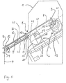
- a housing 1 is indicated, which is constructed as radiation protection cladding and encased a device for the circular shaping 2 of plate-shaped blanks and a welding system 3.
- the radiation protection cladding is made of metal, has no viewing slits and only covered doors.
- a system table 4 is arranged on the plate-shaped Cuts preferably in a trough and / or by means of stops and / or can be stored manually using pre-centered markings.
- an opening 5 is left in the housing 1 through this a device for fixing the plate-shaped blank as a plane Blank 40 in the form of an adjustable to the appropriate plate size
- Fixing frame 6 out of the housing 1 for receiving the blank 40 over the system table 4 can be moved by means of a linear drive 7.
- the device for round shaping 2, the system table 4 and the fixing frame 6 are arranged parallel to a straight line 60 shown in dashed lines, the slope the straight line rises in the direction of the welding system 3.
- the orientation of the Rounding 2, the system table 4 and the fixing frame 6 to the straight line 60 should show that these components are in a common direction to each other are inclined or inclined.
- the slope of the straight line or the System table 4, the fixing frame 6, the device for round shaping 2 and possibly even the welding system 3 is in the range between 5 ° and 60 °, whereby the inclination is chosen such that the weld seam quality is not impaired.
- the straight line 60 has an inclination of 30 °.
- the fixing frame 6 comprises two according to the distance between the to be connected Plate edges 41; 42 of the raw form 40 on a slide 9 adjustable and lengthwise the respective plate edges 41; 42 attachable retaining strips 10; 11.
- the fixing frame 6 further comprises a register device 15, which is designed so that it with one arranged on the leading edge 42 of the plate-like blank 40 Register system 44 interacts (see Fig. 2).
- the leading plate edge 42 for example by means of a pin register 15, which is arranged on the lifting element 13 and a register device 44 - preferably in the form of a pass hole system 44 - the plate-shaped raw form 40 on the support table 4 or on the fixing frame 6 fixable according to register.
- a register device 44 - preferably in the form of a pass hole system 44 - the plate-shaped raw form 40 on the support table 4 or on the fixing frame 6 fixable according to register.
- Contact elements 22 - preferably in the form of suction elements 22 - attached.
- the strip 10 is in accordance with the distance between the plate edges 41; 42 of the raw form 40 can be adjusted on a slide 46 driven by a linear drive 45 and positioned longitudinally on the respective plate edge.
- the position of the plate edge 41 at which the strip 10 is positioned is determined by means of search mechanisms 47 and / or scanning devices 51 arranged on the slide 46.
- the strip 11 is arranged in a stationary manner on the fixing frame 6.
- the bar 10 can alternatively, not shown in detail, also be positioned manually by an operator on the trailing edge 41.
- the lifting elements 12; 13 as suction strips with integrated anund switchable contact elements 14; 22 - preferably vacuum suction cups 14; 22 - formed to hold the blank 40
- the lifting elements 12, 13 are preferably provided with electrical holding magnets with the corresponding Soft iron cores of the strips 10, 11 can cooperate. After actuation the strips 10, 11 and the lifting elements 12, 13 become the plate-shaped raw form 40 on its top, or on the side of the plant table 4 opposite the Fixing frame 6 kept ready for transport.
- the fixing frame 6 further comprises contact elements 23 - preferably designed as suction elements 23.
- the suction elements 23 are arranged in a stationary manner.
- a plate-shaped raw form 40 with a minimum length 49 can be sucked in by means of a lifting device 48, which can be actuated hydraulically or pneumatically, for example, and can be fixed on the fixing frame 6 in an aligned manner.
- the respective additional between the range of the minimum length 49 and the maximum length 50 are also required for the raw mold 40 - Suction elements 14 which can be positioned and switched off can be positioned and switched on to the trailing plate edge 41 in order to suck up such a raw form 40 which extends beyond the minimum length 49 and to fix it in a level manner on the fixing frame 6.
- the suction elements 23 can also be designed to be able to be switched on and off on the raw form 40.
- the raw form 40 is received in register on the fixing frame 6 and can be transported in register.
- the data on the length and / or width of the plate-shaped raw form 40 will not shown in detail, stored in a machine control. From a die Person to be operated by the device can, for example, transmit this data via the Length and / or width of the plate-shaped raw form 40 into the Machine control can be entered. Be about the machine control according to the entered length of the blank 40 for one suction elements 14; 23 automatically activated.
- the optical or mechanical scanning device 51 and / or the search mechanisms 47 the size, i.e. both the length and the width of the plate-shaped blank 40 automatically check and recognize.
- One with the scanning device 51 and / or of search mechanisms 47 related control or Control device positions and then automatically switches the fixation on the fixing frame 6 required suction elements 14; 23 and / or the pin register 15 according to the determined data regarding the position of the trailing plate edge 41 and / or the length and width of the rough form 40 as required.
- the fixing frame 6 is by means of the linear drive 7, which is a cable, a Gear rack or a chain guide supported in rails can be in the Housing 1 mobile over the device for round shaping 2.
- the end positions of the Travel path of the fixing frame 6 are in and outside the housing 1 preferably determined by means of stops.
- the device for round shaping 2 is described in DE 43 11 078 C1, which How it works is analogous to this.
- For the plate edges 41; 42 is one stationary 16 and one rotatable about an axis 18 and along a slide guide 19 transversely movable retaining bar 17 is provided.
- the transversely movable holding bar 17 is positioned according to the respective length of the plate-shaped blank 40.
- the data for positioning the transversely movable holding bar 17 are made available, for example, by the scanning device and / or the machine control described above. If the fixing frame 6 is positioned over the correspondingly set retaining strips 16, 17, the strips 10, 11 of the fixing frame 6 can be electromagnetically attracted and the plate-shaped raw form can be clamped onto the retaining strips 16, 17.
- the empty fixing frame 6 is so far from the work area of the facility Rounding 2 mobile until its housing end 8 the housing opening 5th covers.
- the retaining strips 16, 17 correspond to the length of the processing raw form spaced apart.
- the rough form is 40 by interacting with the pass hole system 44 already described Pin register 15 and the suction elements 14; 23 of the fixing frame 6 on the Retaining strips 16, 17 can be fixed in register.
- the bar is used to form the sleeve 17 rotated and at the same time transversely in the direction of the fixed bar 16 postponed.
- the bar 17 is built on a rotary table 20, which in one Carriage 21 is movable on the slide guide 19.
- the bar 17 passes under the fixed bar 16 and stands after one full turn of the fixed Bar 16 opposite, so that the plate edges 41; 42 also face each other stand.
- a welding system in the form of a laser 3 is arranged in the housing 1 above the strips 16, 17, so that laser cutting and laser welding can be carried out on the sleeve-shaped printing form , as already described in DE 43 38 467 C1.
- the system table can also be designed like a lifting device, on which a stack of several plate-shaped raw molds can be placed. The stack of plate-shaped blanks of the raw forms is conveyed to the fixing frame 6 by means of the lifting device. Starting from the uppermost raw shape, the fixing frame 6 picks up a raw shape in pieces, leveled and transports it to the device for rounding 2.
- a plurality of stacks for example arranged on pallets, can be brought to the position of the lifting device, these being then automatically picked up by the lifting device and the stack being processed piece by piece, as already explained above, the device for generating a sleeve-shaped printing form after processing a plate stack of plate-shaped blanks of the blank forms on the system table or the lifting device can be switched off automatically.
- the stack should then also be inclined identically in accordance with the inclination of the system table and the fixing frame so that the fixing frame can receive and transport the uppermost raw form in accordance with the register.
- a next stack of pallets arranged on a pallet Cuts on and on the lifting device are automatically placed and processed piece by piece.
- An endless production of sleeve-shaped printing forms are created.
- the operation of the device according to the invention proceeds analogously to the work steps already explained in DE 197 10 901 C1. These steps can all be automated.
- the work step of removing the finished sleeve-shaped printing form from the housing 1 or from the device for round shaping 2, the removal by means of a conveyor and the rolling over of the weld seams in the conveyor is also analogous to the devices and described in DE 197 10 901 C1 how they work. In this way, a multiple sequence of the work steps described analogously in DE 197 10 901 C1 can be carried out automatically.
- the device described in the exemplary embodiment is for processing plate-like raw forms, which are made both of non-magnetic material and can also consist of magnetic material, suitable.
- a variant of the device, not shown, is that with a Processing of plate-like raw forms made of a magnetic material exist, which are described in the embodiment as suction elements designed contact elements to be replaced by electrical holding magnets, which like the suction elements position or close the size of the raw form are designed to be switched off.
Landscapes
- Engineering & Computer Science (AREA)
- Manufacturing & Machinery (AREA)
- Making Paper Articles (AREA)
- Manufacture Or Reproduction Of Printing Formes (AREA)
- Laser Beam Processing (AREA)
- Bending Of Plates, Rods, And Pipes (AREA)
Abstract
Description
Der Fixierrahmen umfasst zwei entsprechend dem Abstand der zu verbindenden Plattenkanten der Rohform auf einem Schlitten einstellbare und längs an der jeweiligen Plattenkante ansetzbare Festhalteleisten. Der Fixierrahmen umfasst weiterhin eine Registereinrichtung, die so ausgelegt ist, dass diese mit einem Registersystem der plattenförmigen Rohform zusammenwirkt. So ist der Anfang und das Ende der Rohform jeweils mittels eines Stiftregisters und einem Passloch-System der plattenförmigen Rohform registergerecht an den Festhalteleisten fixierbar.
Die erfindungsgemäße Vorrichtung gestattet einen registergerechten Fertigungsvorgang einer hülsenförmigen Druckform, wobei ein geringerer Verschnitt beim maßhaltigen Ablängen der Rohform im registergerechten, gerundeten Zustand entsteht, da nur für den Anfang bzw. die vorlaufende Kante der plattenförmigen Rohform ein Passloch-System erforderlich ist.
Bedeutungsvoll ist, dass mittels der als Saugelemente und Stiftregister ausgestalteten Fixiermittel oder Kontaktelemente am Fixierrahmen der Vorrichtung sowohl Rohformen aus nicht magnetischem Material, beispielsweise Aluminium, als auch Rohformen aus magnetisierbarem Material plan bzw. eben ausgerichtet fixiert und transportiert werden können.
Die Kontaktelemente zum Fixieren des Endes bzw. der nachlaufenden Kante der Rohform sind vorteilhaft verschiebbar bzw. positionierbar angeordnet, die Fixierung des Endes ist somit frei variabel ausgestaltet, so dass beliebig breite Rohformen fixierbar und zu einer hülsenförmigen Druckform verarbeitbar sind. Vorteilhafterweise sind am positionierbaren Kontaktelement Abtastvorrichtungen, Suchmechanismen oder Sensoren angeordnet mittels denen das Ende und/oder die Länge und/oder die Breite der Rohform ermittelt und die Kontaktelemente entsprechend positioniert werden können. Des weiteren sind die nicht verschiebbaren Kontaktelemente am Fixierrahmen derart angeordnet, dass die Rohform, aus der die üblich eingesetzten Druckformdurchmesser und Druckformbreiten hergestellt werden, ohne Durchhang vom Fixierrahmen bzw. von den Kontaktelementen erfasst und gefördert werden.
- Fig. 1
- eine Seitenansicht einer erfindungsgemäßen Vorrichtung zur Erzeugung einer hülsenförmigen Druckform und
- Fig. 2
- eine Teilansicht eines Fixierrahmens nach Fig. 1.
Die Strahlenschutzverkleidung ist metallisch ausgeführt, hat keine Sichtschlitze und nur überdeckte Türen.
Die Position der Plattenkante 41 an welcher die Leiste 10 positioniert ist, wird mittels am Schlitten 46 angeordneten Suchmechanismen 47 und/oder Abtastvorrichtungen 51 ermittelt. Die Leiste 11 ist ortsfest am Fixierrahmen 6 angeordnet. Die Leiste 10 kann alternativ, nicht näher dargestellt, auch manuell von einer Bedienungsperson an die nachlaufende Kante 41 positioniert werden.
Für plattenförmige Rohformen 40, die über die Mindestlänge 49 hinausgehen und bis zu einer maximalen Länge 50 ausgebildet sind, sind je nach tatsächlicher Länge der Rohform 40 die jeweiligen zwischen dem Bereich der Mindestlänge 49 und der maximalen Länge 50 noch zusätzlich benötigten an die Rohform 40 an- und abstellbar ausgestalteten Saugelemente 14 an die nachlaufende Plattenkante 41 positionierbar und zuschaltbar, um eine derartige über die Mindestlänge 49 hinausgehende Rohform 40 lagestabil anzusaugen und am Fixierrahmen 6 eben ausgerichtet zu fixieren.
Alternativ können die Saugelemente 23 auch an die Rohform 40 an- und abstellbar ausgestaltet sein.
Bei Aktivierung der die nachlaufende Plattenkante 41 ansaugenden und somit fixierenden Saugelemente 14, sowie Aktivierung der Saugelemente 23 und des mit dem Passloch-System 44 zusammenwirkenden Stiftregisters 15, ist die Rohform 40 registergerecht am Fixierrahmen 6 aufgenommen und kann registergerecht transportiert werden.
Ist der Fixierrahmen 6 über den entsprechend eingestellten Festhalteleisten 16, 17 positioniert, sind die Leisten 10, 11 des Fixierrahmens 6 elektromagnetisch anziehbar und die plattenförmige Rohform auf die Festhalteleisten 16, 17 klemmbar.
Alternativ kann, nicht näher dargestellt, der Anlagetisch auch wie eine Hubvorrichtung ausgestaltet sein, auf welchem ein Stapel von mehreren plattenförmigen Rohformen aufgelegt werden kann. Mittels der Hubvorrichtung wird der Stapel von plattenförmigen Zuschnitten der Rohformen an den Fixierrahmen 6 gefördert. Der Fixierrahmen 6 nimmt von diesem Stapel, ausgehend von der obersten Rohform, stückweise eine Rohform eben ausgerichtet auf und transportiert diese zur Einrichtung zur Rundformung 2.
Es ist denkbar, dass eine Vielzahl von Stapeln, beispielsweise auf Paletten angeordnet, an die Position der Hubvorrichtung verbracht werden kann, wobei diese dann von der Hubvorrichtung automatisch aufgenommen werden und der Stapel wie oben bereits erläutert stückweise abgearbeitet wird, wobei die Vorrichtung zur Erzeugung einer hülsenförmigen Druckform nach Abarbeitung eines Plattenstapels von plattenförmigen Zuschnitten der Rohformen auf dem Anlagetisch bzw. der Hubvorrichtung selbsttätig abschaltbar ist. Der Stapel soll dann entsprechend der Schrägstellung des Anlagetisches und des Fixierrahmens ebenfalls identisch geneigt sein, damit der Fixierrahmen die oberste Rohform registergerecht aufnehmen und transportierten kann.
Der Arbeitsschritt der Entnahme der fertigen hülsenförmigen Druckform aus dem Gehäuse 1 bzw. von der Einrichtung zur Rundformung 2, der Abtransport mittels einer Fördereinrichtung und das Überrollen der Schweißnähte in der Fördereinrichtung ist ebenfalls analog zu der in der DE 197 10 901 C1 bereits beschrieben Vorrichtungen und deren Funktionsweise. Auf diese Weise kann eine mehrfache Abfolge der analog in der DE 197 10 901 C1 beschriebenen Arbeitsschritte automatisch durchgeführt werden.
- 1
- Gehäuse
- 2
- Einrichtung zur Rundformung
- 3
- Schweißanlage
- 4
- Anlagetisch
- 5
- Öffnung
- 6
- Fixierrahmen
- 7
- Linearantrieb
- 8
- Gehäuseabschluss
- 9
- Schlitten
- 10
- Festhalteleiste
- 11
- Festhalteleiste
- 12
- Hubelement
- 13
- Hubelement
- 14
- Positionierbares Kontaktelement / Saugelement
- 15
- Stiftregister
- 16
- Festhalteleiste
- 17
- Festhalteleiste
- 18
- Achse
- 19
- Gleitführung
- 20
- Rundtisch
- 21
- Schlitten
- 22
- Kontaktelement / Saugelement
- 23
- Kontaktelement / Saugelement
- 40
- Rohform
- 41
- nachlaufende Kante
- 42
- vorlaufende Kante
- 43 44
- Passloch-System
- 45
- Linearantrieb
- 46
- Schlitten
- 47
- Suchmechanismen
- 48
- Hubeinrichtung
- 49
- Mindestlänge
- 50
- Maximale Länge
- 51
- Abtastvorrichtung
- 60
- Gerade
Claims (10)
- Vorrichtung zur Erzeugung einer hülsenförmigen Druckform aus einem plattenförmigen Zuschnitt, die eine Einrichtung zur Rundformung (2) der Rohform (40) und eine Schweißanlage (3), mit dieser die den Anfang und Ende der Druckform bildenden Plattenkanten (41; 42) maßhaltig zuschneidbar und verschweißbar sind, einen Anlagetisch (4) für die plattenförmige Rohform (40) sowie eine verfahrbare Einrichtung zur Aufnahme und zum Transport der Rohform (40) an die Einrichtung zur Rundformung (2) umfasst, wobei die verfahrbare Einrichtung einen Fixierrahmen (6) aufweist, der zwei entsprechend dem Abstand der zu verbindenden Plattenkanten (41; 42) einstellbare und längs der jeweiligen Plattenkante ansetzbare Hubelemente (12; 13) aufweist, dadurch gekennzeichnet, dass
die den Anfang bildende Plattenkante (42) mit einer Registereinrichtung (44) ausgestattet ist, ein Hubelement (13) mindestens eine mit der Registereinrichtung (44) zusammenwirkende Registereinrichtung (15) und mindestens ein Kontaktelement (22) zum registergerechten Fixieren umfasst, das andere Hubelement (12) mit mindestens einem Kontaktelement (14) ausgestattet ist, der Anlagetisch (4) in Richtung der Schweißanlage (3) ansteigend angeordnet ist, so dass sich die mittels der Registereinrichtung (15) fixierte Rohform (40) auf Grund ihres Eigengewichtes in Richtung ihrer das Ende bildenden Plattenkante (41) selbst entlang dem schräg verlaufenden Anlagetisch (4) registergerecht und eben ausrichtet. - Vorrichtung nach Anspruch 1, dadurch gekennzeichnet, dass der Fixierrahmen (6) Kontaktelemente (23) aufweist, welche in einem Bereich einer Mindestlänge (49) der auf dem Anlagetisch (4) aufzubringenden Rohform (40) angeordnet sind und die Kontaktelemente (14) in einem Bereich zwischen der Mindestlänge (49) und einer maximalen Länge (50) der auf dem Anlagetisch (4) aufzubringenden Rohform (40) positionierbar sind.
- Vorrichtung nach Anspruch 2, dadurch gekennzeichnet, dass die Rohform (40) der Mindestlänge (49) mit ortsfest angeordneten und gleichzeitig die Rohform (40) aufnehmenden Kontaktelementen (23) fixierbar ist und die über die Mindestlänge (49) hinausragende Rohform (40) mittels entsprechend ihrer tatsächlichen Länge zum ebenen fixieren benötigte an die Plattenkante (41) positionierbar und zuschaltbar aufnehmende Kontaktelemente (14) fixierbar ist.
- Vorrichtung nach einem der Ansprüche 1 bis 3, dadurch gekennzeichnet, dass die auf dem Anlagetisch (4) aufzubringende Rohform (40) mittels einer Hubvorrichtung (48) an dem Fixierrahmen (6) positionierbar ist.
- Vorrichtung nach einem der Ansprüche 1 bis 4, dadurch gekennzeichnet, dass die Einrichtung zur Rundformung (2) für die zu verbindenden Plattenkanten (41; 42) eine feststehend angeordnete Festhalteleiste (16) und eine auf einem drehbar und transversal bewegbar angeordneten Rundtisch (20) sitzende Festhalteleiste (17) aufweist, wobei die feststehend angeordnete Festhalteleiste (16) die Plattenkante (42) aufnimmt und die transversal bewegbare Festhalteleiste (17) entsprechend der tatsächlichen Länge der Rohform (40) sich ergebenden Position der Plattenkante (41) zur Aufnahme dieser positionierbar ist, die Rohform (40) mittels des Fixierrahmens (6) derart auf den Festhalteleisten (16, 17) positionierbar ist, dass bei einer vollen Umdrehung und gleichzeitig transversaler Verschiebung des Rundtisches (20) in Richtung der feststehenden Leiste (16) die Leisten (16, 17) unter Ausbildung einer Hülse zum maßhaltigen Ablängen und Verschweißen der Plattenkanten (41; 42) in Position bringbar sind.
- Vorrichtung nach einem der Ansprüche 1 bis 5, dadurch gekennzeichnet, dass die tatsächliche Länge und Breite der Rohform (40) mittels einer optischen oder mechanischen Abtastvorrichtung (51) und/oder Suchmechanismen (47) ermittelbar ist.
- Vorrichtung nach Anspruch 6, dadurch gekennzeichnet, dass die Abtastvorrichtung (51) und/oder die Suchmechanismen (47) die tatsächliche Länge und Breite der Rohform (40) in einer Maschinensteuerung übermittelbare Daten umwandelt, wobei gemäß der Daten die zum ebenen fixieren der Rohform (40) benötigten Kontaktelemente (14; 23) in ihrer Wirkung zu- und abschaltbar sind.
- Vorrichtung nach einem der Ansprüche 1 bis 7, dadurch gekennzeichnet, dass auf den Anlagetisch (4) mehrere Rohformen in Form eines Plattenstapels legbar sind, vom Plattenstapel die jeweils oben liegende Rohform (40) mittels des Fixierrahmens (6) aufnehmbar ist und nach Abarbeitung des Plattenstapels selbsttätig abschaltbar ist.
- Vorrichtung nach einem der Ansprüche 1 bis 8, dadurch gekennzeichnet, dass die Schweißanlage (3) in Form mindestens eines Lasers im Gehäuse (1) über der Einrichtung zur Rundformung (9) positioniert ist, so daß Laserschneiden und Laserschweißen maschinell durchführbar sind.
- Vorrichtung nach einem der vorhergehenden Anspruche, dadurch gekennzeichnet, dass die Kontaktelemente (14; 22; 23) als Saugelemente und/oder elektrische Haltemagnete ausgeführt sind.
Applications Claiming Priority (2)
| Application Number | Priority Date | Filing Date | Title |
|---|---|---|---|
| DE10260445 | 2002-12-21 | ||
| DE10260445A DE10260445A1 (de) | 2002-12-21 | 2002-12-21 | Vorrichtung zur Erzeugung einer hülsenförmigen Druckform |
Publications (3)
| Publication Number | Publication Date |
|---|---|
| EP1431033A2 true EP1431033A2 (de) | 2004-06-23 |
| EP1431033A3 EP1431033A3 (de) | 2005-09-07 |
| EP1431033B1 EP1431033B1 (de) | 2010-05-05 |
Family
ID=32336564
Family Applications (1)
| Application Number | Title | Priority Date | Filing Date |
|---|---|---|---|
| EP03028451A Expired - Lifetime EP1431033B1 (de) | 2002-12-21 | 2003-12-12 | Vorrichtung zur Erzeugung einer hülsenförmigen Druckform |
Country Status (4)
| Country | Link |
|---|---|
| US (1) | US6899264B2 (de) |
| EP (1) | EP1431033B1 (de) |
| JP (1) | JP4167970B2 (de) |
| DE (2) | DE10260445A1 (de) |
Cited By (1)
| Publication number | Priority date | Publication date | Assignee | Title |
|---|---|---|---|---|
| CN115156745A (zh) * | 2022-08-03 | 2022-10-11 | 阳江市力王刀具有限公司 | 一种厨房刀具用高强度不锈钢板材的激光切割设备 |
Family Cites Families (10)
| Publication number | Priority date | Publication date | Assignee | Title |
|---|---|---|---|---|
| US3775586A (en) * | 1971-08-10 | 1973-11-27 | Int Laser Systems Inc | Enclosed laser apparatus with remote workpiece control |
| GB1415835A (en) * | 1971-09-24 | 1975-11-26 | Mannesmann Meer Ag | Hydraulic presses |
| JPS58107542A (ja) * | 1981-12-21 | 1983-06-27 | Fuji Photo Film Co Ltd | 記録材料装着装置 |
| US5149934A (en) * | 1991-09-24 | 1992-09-22 | Ferranti Sciaky, Inc. | High voltage electron beam gun |
| DE4140768C2 (de) * | 1991-12-11 | 1994-08-18 | Roland Man Druckmasch | Offset-Druckform |
| DE4311078C1 (de) * | 1993-04-03 | 1994-05-26 | Roland Man Druckmasch | Vorrichtung zur Erzeugung einer Hülse, insbesondere einer hülsenförmigen Druckform, mit zusammenhängender Umfangsfläche |
| DE4338467C1 (de) * | 1993-11-11 | 1995-02-23 | Roland Man Druckmasch | Verfahren zur Herstellung einer hülsenförmigen Druckform |
| DE19710901C1 (de) * | 1997-03-15 | 1998-08-13 | Roland Man Druckmasch | Vorrichtung zur Erzeugung einer hülsenförmigen Druckform |
| US6112663A (en) * | 1999-03-25 | 2000-09-05 | Creo Products Inc. | Method for loading a printing plate onto an imaging cylinder using a suction/pressure table |
| DE10116609A1 (de) * | 2001-04-03 | 2002-11-07 | Roland Man Druckmasch | Vorrichtung zur Erzeugung einer hülsenförmigen Druckform |
-
2002
- 2002-12-21 DE DE10260445A patent/DE10260445A1/de not_active Withdrawn
-
2003
- 2003-12-08 JP JP2003409504A patent/JP4167970B2/ja not_active Expired - Fee Related
- 2003-12-12 DE DE50312691T patent/DE50312691D1/de not_active Expired - Lifetime
- 2003-12-12 EP EP03028451A patent/EP1431033B1/de not_active Expired - Lifetime
- 2003-12-22 US US10/745,317 patent/US6899264B2/en not_active Expired - Fee Related
Cited By (1)
| Publication number | Priority date | Publication date | Assignee | Title |
|---|---|---|---|---|
| CN115156745A (zh) * | 2022-08-03 | 2022-10-11 | 阳江市力王刀具有限公司 | 一种厨房刀具用高强度不锈钢板材的激光切割设备 |
Also Published As
| Publication number | Publication date |
|---|---|
| US20040155016A1 (en) | 2004-08-12 |
| US6899264B2 (en) | 2005-05-31 |
| JP4167970B2 (ja) | 2008-10-22 |
| EP1431033B1 (de) | 2010-05-05 |
| JP2004203029A (ja) | 2004-07-22 |
| DE50312691D1 (de) | 2010-06-17 |
| DE10260445A1 (de) | 2004-07-08 |
| EP1431033A3 (de) | 2005-09-07 |
Similar Documents
| Publication | Publication Date | Title |
|---|---|---|
| DE2325519C3 (de) | Anlage zum Schneiden von Walzblech zu kombinierten Formaten | |
| EP2059468B1 (de) | Registereinzugsvorrichtung | |
| EP0667237B1 (de) | Vorrichtung zum automatischen Wechseln von Druckplatten | |
| DE3804443C2 (de) | ||
| DE68909954T2 (de) | Stapelvorrichtung. | |
| DE3305081C2 (de) | Vorrichtung zum Vereinzeln des jeweils obersten Blattes eines Blattstapels | |
| DE3744315C2 (de) | ||
| DE4424931C2 (de) | Vorrichtung zur Montage, Demontage und Transport von leicht biegbaren, bogenförmigen Gegenständen mit Einhängeabkantungen | |
| DE102008010985A1 (de) | Bogenbremseinrichtung | |
| EP1018409A1 (de) | Verfahren zur Bildung und Weiterverarbeitung von kleinen Blattgutstapeln | |
| DE2839992A1 (de) | Werkzeugwechselvorrichtung | |
| EP1018408A1 (de) | Planschneidmaschine zum Schneiden von gestapeltem, blattförmigem Gut | |
| EP0740607A1 (de) | Vorrichtung zur montage, demontage und transport von leicht biegbaren, bogenförmigen gegenständen mit einhängeabkantungen | |
| DE4406740B4 (de) | Vorrichtung zur Passerkorrektur in einer Bogendruckmaschine | |
| EP3241791A2 (de) | Verfahren zur herstellung von stapeln aus bögen | |
| DE69300622T2 (de) | Bewegliche Vorrichtung und Verfahren zum Greifen und Transportieren von Blechen, wie zu formenden Türen, zu und von einer ausgerichteten Formposition in einer Arbeitsstation. | |
| DE19710901C1 (de) | Vorrichtung zur Erzeugung einer hülsenförmigen Druckform | |
| EP1611039A1 (de) | Transporteinrichtung, insbesondere für plattenförmige werkstücke | |
| EP0498071B1 (de) | Verfahren zum Vorstapeln in einem Bogenanleger von Rotationsdruckmaschinen | |
| EP1431033B1 (de) | Vorrichtung zur Erzeugung einer hülsenförmigen Druckform | |
| EP0619185B1 (de) | Vorrichtung zur Erzeugung einer Hülse, insbesondere einer hülsenförmigen Druckform, mit Zusammenhängender Umfangsfläche | |
| EP0478903B1 (de) | Wechselkassettenvorrichtung für eine Rollenrotationsdruckmaschine | |
| EP1247618B1 (de) | Vorrichtung zur Erzeugung einer hülsenförmigen Druckform | |
| DE102013001778A1 (de) | Überwachungsverfahren zur Kollisionsvermeidung einer Stanzmaschine mit Bremsbürste | |
| DE102010032643A1 (de) | Vorrichtung und Verfahren zum Wechseln des Oberwerkzeugs einer Stanzstation einer Bogenstanzmaschine |
Legal Events
| Date | Code | Title | Description |
|---|---|---|---|
| PUAI | Public reference made under article 153(3) epc to a published international application that has entered the european phase |
Free format text: ORIGINAL CODE: 0009012 |
|
| AK | Designated contracting states |
Kind code of ref document: A2 Designated state(s): AT BE BG CH CY CZ DE DK EE ES FI FR GB GR HU IE IT LI LU MC NL PT RO SE SI SK TR |
|
| AX | Request for extension of the european patent |
Extension state: AL LT LV MK |
|
| PUAL | Search report despatched |
Free format text: ORIGINAL CODE: 0009013 |
|
| AK | Designated contracting states |
Kind code of ref document: A3 Designated state(s): AT BE BG CH CY CZ DE DK EE ES FI FR GB GR HU IE IT LI LU MC NL PT RO SE SI SK TR |
|
| AX | Request for extension of the european patent |
Extension state: AL LT LV MK |
|
| 17P | Request for examination filed |
Effective date: 20060224 |
|
| AKX | Designation fees paid |
Designated state(s): DE FR GB IT |
|
| 17Q | First examination report despatched |
Effective date: 20071107 |
|
| RAP1 | Party data changed (applicant data changed or rights of an application transferred) |
Owner name: MANROLAND AG |
|
| GRAP | Despatch of communication of intention to grant a patent |
Free format text: ORIGINAL CODE: EPIDOSNIGR1 |
|
| GRAS | Grant fee paid |
Free format text: ORIGINAL CODE: EPIDOSNIGR3 |
|
| GRAA | (expected) grant |
Free format text: ORIGINAL CODE: 0009210 |
|
| AK | Designated contracting states |
Kind code of ref document: B1 Designated state(s): DE FR GB IT |
|
| REG | Reference to a national code |
Ref country code: GB Ref legal event code: FG4D Free format text: NOT ENGLISH |
|
| REF | Corresponds to: |
Ref document number: 50312691 Country of ref document: DE Date of ref document: 20100617 Kind code of ref document: P |
|
| PGFP | Annual fee paid to national office [announced via postgrant information from national office to epo] |
Ref country code: FR Payment date: 20110104 Year of fee payment: 8 |
|
| PLBE | No opposition filed within time limit |
Free format text: ORIGINAL CODE: 0009261 |
|
| STAA | Information on the status of an ep patent application or granted ep patent |
Free format text: STATUS: NO OPPOSITION FILED WITHIN TIME LIMIT |
|
| PGFP | Annual fee paid to national office [announced via postgrant information from national office to epo] |
Ref country code: GB Payment date: 20101221 Year of fee payment: 8 |
|
| 26N | No opposition filed |
Effective date: 20110208 |
|
| REG | Reference to a national code |
Ref country code: DE Ref legal event code: R097 Ref document number: 50312691 Country of ref document: DE Effective date: 20110207 |
|
| PGFP | Annual fee paid to national office [announced via postgrant information from national office to epo] |
Ref country code: DE Payment date: 20101222 Year of fee payment: 8 Ref country code: IT Payment date: 20101223 Year of fee payment: 8 |
|
| GBPC | Gb: european patent ceased through non-payment of renewal fee |
Effective date: 20111212 |
|
| REG | Reference to a national code |
Ref country code: FR Ref legal event code: ST Effective date: 20120831 |
|
| REG | Reference to a national code |
Ref country code: DE Ref legal event code: R119 Ref document number: 50312691 Country of ref document: DE Effective date: 20120703 |
|
| PG25 | Lapsed in a contracting state [announced via postgrant information from national office to epo] |
Ref country code: DE Free format text: LAPSE BECAUSE OF NON-PAYMENT OF DUE FEES Effective date: 20120703 Ref country code: GB Free format text: LAPSE BECAUSE OF NON-PAYMENT OF DUE FEES Effective date: 20111212 |
|
| PG25 | Lapsed in a contracting state [announced via postgrant information from national office to epo] |
Ref country code: IT Free format text: LAPSE BECAUSE OF NON-PAYMENT OF DUE FEES Effective date: 20111212 |
|
| PG25 | Lapsed in a contracting state [announced via postgrant information from national office to epo] |
Ref country code: FR Free format text: LAPSE BECAUSE OF NON-PAYMENT OF DUE FEES Effective date: 20120102 |