EP1430966A2 - Verfahren zum Herstellen eines Werkstückes aus metallischem Werkstoff und Umformpresse zur Durchführung des Verfahrens - Google Patents
Verfahren zum Herstellen eines Werkstückes aus metallischem Werkstoff und Umformpresse zur Durchführung des Verfahrens Download PDFInfo
- Publication number
- EP1430966A2 EP1430966A2 EP03029185A EP03029185A EP1430966A2 EP 1430966 A2 EP1430966 A2 EP 1430966A2 EP 03029185 A EP03029185 A EP 03029185A EP 03029185 A EP03029185 A EP 03029185A EP 1430966 A2 EP1430966 A2 EP 1430966A2
- Authority
- EP
- European Patent Office
- Prior art keywords
- profile
- forming
- stamps
- stamp
- tool
- Prior art date
- Legal status (The legal status is an assumption and is not a legal conclusion. Google has not performed a legal analysis and makes no representation as to the accuracy of the status listed.)
- Withdrawn
Links
Images



Classifications
-
- B—PERFORMING OPERATIONS; TRANSPORTING
- B21—MECHANICAL METAL-WORKING WITHOUT ESSENTIALLY REMOVING MATERIAL; PUNCHING METAL
- B21D—WORKING OR PROCESSING OF SHEET METAL OR METAL TUBES, RODS OR PROFILES WITHOUT ESSENTIALLY REMOVING MATERIAL; PUNCHING METAL
- B21D22/00—Shaping without cutting, by stamping, spinning, or deep-drawing
- B21D22/02—Stamping using rigid devices or tools
- B21D22/025—Stamping using rigid devices or tools for tubular articles
-
- B—PERFORMING OPERATIONS; TRANSPORTING
- B21—MECHANICAL METAL-WORKING WITHOUT ESSENTIALLY REMOVING MATERIAL; PUNCHING METAL
- B21D—WORKING OR PROCESSING OF SHEET METAL OR METAL TUBES, RODS OR PROFILES WITHOUT ESSENTIALLY REMOVING MATERIAL; PUNCHING METAL
- B21D26/00—Shaping without cutting otherwise than using rigid devices or tools or yieldable or resilient pads, i.e. applying fluid pressure or magnetic forces
- B21D26/02—Shaping without cutting otherwise than using rigid devices or tools or yieldable or resilient pads, i.e. applying fluid pressure or magnetic forces by applying fluid pressure
- B21D26/033—Deforming tubular bodies
- B21D26/037—Forming branched tubes
-
- B—PERFORMING OPERATIONS; TRANSPORTING
- B21—MECHANICAL METAL-WORKING WITHOUT ESSENTIALLY REMOVING MATERIAL; PUNCHING METAL
- B21D—WORKING OR PROCESSING OF SHEET METAL OR METAL TUBES, RODS OR PROFILES WITHOUT ESSENTIALLY REMOVING MATERIAL; PUNCHING METAL
- B21D53/00—Making other particular articles
- B21D53/88—Making other particular articles other parts for vehicles, e.g. cowlings, mudguards
Definitions
- the invention relates to a method for producing a Workpiece made of metallic material, in particular Aluminum, with adjacent shapes, in particular a wishbone connection with a double-walled Cathedral for motor vehicles, by means of internal high pressure forming, after which a tubular blank in one Forming tool with a high-pressure forming Active medium is applied.
- a Workpiece made of metallic material in particular Aluminum
- adjacent shapes in particular a wishbone connection with a double-walled Cathedral for motor vehicles
- Active medium can be applied.
- the active medium can act as a gaseous or liquid medium.
- a tubular support is known as part of a Chassis for a motor vehicle, which with at least one deviating from its cross-section and opposite its outer surface transversely projecting bracket for at least indirect fixation of chassis components such as B. wishbones or space arms is provided.
- the Bracket is through non-cutting hydro-forming of the material the support wall is formed (DE 44 42 150 C2).
- the invention has for its object a method for Manufacture of a workpiece from metallic material, in particular aluminum, the embodiment described above to indicate with which is relatively strong Formations on a tubular workpiece without essential axial material flow in a flawless manner have it made.
- suitable forming press can be created using this method.
- the central profile stamp and the side profile stamp can be driven in alternation.
- several profile stamps can be used within the scope of the invention in predetermined angular positions to the main tool axis retractable into the mold recess and of course be extendable, which is used to expand the Have shaping options used. They can always used profile stamp in any order and Direction to each other and depending on the active media pressure be proceeded to a desired one To achieve formation.
- the profile stamps are preferred formed with shaping stamp faces. Predefined distances for the material flow should be provided in the depth of the mold.
- the profile stamp can be regulated or controlled drives can be moved.
- the profile stamp can be driven with vibration excitation and can be used as oscillating profile stamps work. Consequently, the Profile stamps in certain process sections Carry out alternating movement to the shaping options to increase further.
- the profile stamps preferably oscillate with an amplitude of 0.1 to 0.3 mm and a frequency from 2 to 3 Hz. A minimization of the friction conditions is achieved in particular if after another Proposal of the invention that is under high pressure forming Active medium in a range from approx.
- the oscillation of the Profile stamp and the pulsation of the active medium superimposed.
- the profile stamps are in the form space of the Forming tool can be moved forward to a material pre-distribution also inside into the mold space with a subsequent one Material expansion outwards into the mold recess realize.
- the profile stamps are expedient between the upper part of the tool and the lower part of the tool Forming tool performed while the mold recess on the side of the forming space of the forming tool or orthogonal to it.
- a forming press with a forming tool and a molding space 1 between the upper tool part 2 and lower tool part 3 for producing workpieces 4 made of metallic materials, especially aluminum, in Represented ways of cold or hot forming.
- This Forming press has retractable into the mold space 1 Forming stamp 5 with high pressure holes 6, which on a hollow blank 7 located in the molding space 1, e.g. B. a tube, according to the internal high pressure forming work, one under high forming pressure Active medium - gaseous or liquid medium - the Forming supported.
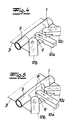
- the tool upper part 2 and / or The lower tool part 3 has a formation 8 one of the formation 8 on the resulting workpiece corresponding recess 9 with at least one in the Form recess 9 retractable die 10a on the shape of the resulting formation 8 by a Targeted control of the material flow and the Material distribution in the mold recess 9 influenced and controlled.
- This profile stamp 10a can also influence on the forming speed and depth of the take the resulting shape 8.
- the Profile stamps 10a, 10b, 10c are shaping Stamp faces formed.
- the Profile stamps 10a, 10b, 10c are regulated or Controlled drives can be moved and also with vibration excitation drivable so that it is then oscillating Work profile stamp.
- the profile stamp 10a, 10b, 10c are optionally up to the Form space 1 of the forming tool can be moved forward and between the Tool upper part 2 and the lower tool part 3 of the Forming tool performed.
- the mold recess 9 is located laterally on the mold space 1 and is orthogonal to the Form space 1 arranged.
- FIG. 1 there are the profile stamps 10a, 10b, 10c in starting position. 2 has a material pre-distribution occurred.
- the profile stamp 10a, 10b, 10c have a predetermined area of the mold recess 9 released so that a certain proportion of the material in the space that has become free has penetrated and through the Bulged effect of the active media pressure.
- 3 is moved by a movement of the profile stamp 10a, 10b, 10c in Direction of the formations 8 to be produced and the finished part shape by the slide end faces in a predetermined position.
- the middle profile stamp 10a is a material pre-distribution by advancing the middle profile stamp 10a into the blank 7.
- the next step is to expand the internally transported material by increasing internal pressure to the outside world and consequently to those of Profile stamps 10a, 10b 10c left open space in the Form recess 9, as shown in FIG. 5.
- the middle profile stamp 10a is simultaneously from the under Workpiece wall under internal pressure by a certain amount pushed back or reduced defined.
- Fig. 6 provides an ancestor of the side profile stamp 10b, 10c for the transport of the pre-distributed material in the direction the formation to be generated.
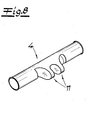
- 7 is the finished form shown. 8, the finished workpiece 4 is in the Embodiment of a wishbone connection with a double-walled cathedral 11 shown.
Landscapes
- Engineering & Computer Science (AREA)
- Mechanical Engineering (AREA)
- Physics & Mathematics (AREA)
- Fluid Mechanics (AREA)
- Shaping Metal By Deep-Drawing, Or The Like (AREA)
- Mounting, Exchange, And Manufacturing Of Dies (AREA)
Abstract
Description
- Diese Maßnahmen der Erfindung haben zur Folge, dass mit Hilfe der Profilstempel der Materialfluss und folglich die Werkstoffbewegung in die Formausnehmung eines Umformwerkzeuges derart gesteuert werden kann, dass gerade ausreichend viel Werkstoff in die Formausnehmung abfließt, um dort die gewünschte Ausformung entstehen zu lassen. Die Profilstempel geben in einer vorgegebenen Position einen entsprechenden Bereich der Formausnehmung frei, so dass ein gewisser Anteil des Werkstückwerkstoffes in den frei gewordenen Raum durch die Wirkung des Wirkmediendruckes eindringen und dort ausbauchen kann. Insoweit wird zunächst eine Materialvorverteilung erreicht. Durch eine anschließend erfolgende Bewegung der Profilstempel beispielsweise in Richtung auf den Formraum des Umformwerkzeuges wird der vorverteilte bzw. ausgebauchte Werkstoff in Richtung der zu erzeugenden Ausformung transportiert und die Fertigteilform durch die Stirnflächen der Profilstempel in einer festgelegten Position gebildet.
- Fig. 1
- in schematischer Darstellung ein Umformwerkzeug mit drei Profilstempeln in perspektivischer Draufsicht und Ausgangssituation,
- Fig. 2
- den Gegenstand nach Fig. 1 nach einer Werkstoffvorverteilung in die Formausnehmung bei zurückgefahrenen Profilstempeln,
- Fig. 3
- den Gegenstand nach Fig. 2 nach dem Fertigformen des Werkstückes mit vorgefahrenen Profilstempeln,
- Fig. 4
- eine abgewandelte Ausführungsform des Gegenstandes nach Fig. 1 mit einem mittig vorfahrbaren Profilstempel zur Werkstoffvorverteilung nach innen,
- Fig. 5
- den Gegenstand nach Fig. 4 mit Werkstückaufweitung nach außen in die Formausnehmung und mittig zurückgefahrenem Profilstempel,
- Fig. 6
- den Gegenstand nach Fig. 5 mit seitlich vorgefahrenen Profilstempeln,
- Fig. 7
- den Gegenstand nach Fig. 6 nach dem Fertigformen des Werkstückes und
- Fig. 8
- das fertige Werkstück als Querlenkeranbindung mit einem doppelwandigen Dom.
Claims (24)
- Verfahren zum Herstellen eines Werkstückes aus metallischem Werkstoff, insbesondere Aluminium, mit nebeneinander liegenden Ausformungen, insbesondere einer Querlenkeranbindung mit einem doppelwandigen Dom für Kraftfahrzeuge, im Wege einer Innenhochdruckumformung, wonach ein rohrförmiger Rohling in einem Umformwerkzeug mit einem unter Umformhochdruck stehenden Wirkmedium beaufschlagt wird, dadurch gekenn-zeichnet, dass zum Ausformen des doppelwandigen Doms ein zentraler Profilstempel gegen den unter Innenhochdruck stehenden Rohling orthogonal zu seiner Hauptachse im Umformbereich vorgefahren wird und beidseitig des zentralen Profilstempels seitliche Profilstempel in einem vorgegebenen Anstellwinkel und mit vorgegebenem Abstand unter Erzeugung der beiden Domwände gegen den Rohling vorgefahren werden.
- Verfahren nach Anspruch 1, dadurch gekennzeichnet, dass zunächst lediglich der zentrale Profilstempel zum Vorstülpen des Rohlings im Umformbereich vorgefahren wird und nach dem Vorstülpen der zentrale Profilstempel und die beiden seitlichen Profilstempel vorgefahren werden.
- Verfahren nach Anspruch 1 oder 2, dadurch gekennzeichnet, dass das Vorstülpen des Rohlings außerhalb des Umformwerkzeuges vorgenommen wird.
- Verfahren nach einem der Ansprüche 1 bis 3, dadurch gekennzeichnet, dass der zentrale Profilstempel und die seitlichen Profilstempel im gegenseitigen Wechsel vorgefahren werden.
- Verfahren nach einem der Ansprüche 1 bis 4, dadurch gekennzeichnet, dass die Profilstempel oszillierend vorgefahren werden.
- Verfahren nach einem der Ansprüche 1 bis 5, dadurch gekennzeichnet, dass die Profilstempel mit einer Amplitude von 0,1 bis 0,3 mm und einer Frequenz von 2 bis 3 Hz oszillierend vorgefahren werden.
- Verfahren nach einem der Ansprüche 1 bis 6, dadurch gekennzeichnet, dass die Profilstempel bei pulsierendem Wirkmedium vorgefahren werden.
- Verfahren nach einem der Ansprüche 1 bis 7, dadurch gekennzeichnet, dass das unter Umformhochdruck stehende Wirkmedium in einem Bereich von ca. 60 bis 100 bar und in Abständen von ca. 10 Sek. pulsiert während die Profilstempel vorgefahren werden.
- Verfahren nach einem der Ansprüche 1 bis 8, dadurch gekennzeichnet, dass die Profilstempel bei pulsierendem Wirkmedium oszillierend vorgefahren werden.
- Verfahren nach einem der Ansprüche 1 bis 9, dadurch gekennzeichnet, dass die Profilstempel gekühlt und/oder geschmiert werden.
- Verfahren nach einem der Ansprüche 1 bis 10, dadurch gekennzeichnet, dass als Wirkmedium ein in Erdgas, z. B. Stickstoff verwendet wird.
- Verfahren nach einem der Ansprüche 1 bis 11, dadurch gekennzeichnet, dass als Wirkmedium Druckluft oder Sauerstoff verwendet wird.
- Verfahren nach einem der Ansprüche 1 bis 12, dadurch gekennzeichnet, dass als Wirkmedium Hydraulikflüssigkeit oder ein Thermoöl verwendet wird.
- Umformpresse zur Durchführung des Verfahrens nach einem der Ansprüche 1 bis 13, mit einem Umformwerkzeug und einem Formraum zwischen Werkzeugunterteil und Werkzeugoberteil zum Herstellen von Werkstücken aus metallischen Werkstoffen, insbesondere Aluminium, im Wege einer Umformung, und mit in den Formraum einfahrbaren Umformstempeln mit Hochdruckbohrungen, welche auf einen in dem Formraum befindlichen hohlen Rohling nach Maßgabe der Innenhochdruckumformungen arbeiten, wobei ein unter Umformhochdruck stehendes Wirkmedium die Umformung unterstützt, dadurch gekennzeichnet, dass das Werkzeugoberteil (2) und/oder Werkzeugunterteil (3) zur Erzeugung einer Ausformungen (8) abgestimmte Formausnehmung (9) mit zumindest einem in die Formausnehmung (9) einfahrbaren Profilstempel 10a aufweist, der die Formgebung der entsprechenden Ausformung (8) durch eine zielgerichtete Steuerung der Werkstoffverteilung in der Formausnehmung (9) beeinflusst und kontrolliert.
- Umformpresse nach Anspruch 14, dadurch gekennzeichnet, dass mehrere Profilstempel (10a, 10b, 10c) in vorgegebenen Winkelpositionen zu der Werkzeughauptachse (H) in die Formausnehmung (9) einfahrbar sind.
- Umformpresse nach Anspruch 14 oder 15, dadurch gekennzeichnet, dass die Profilstempel (10a, 10b, 10c) mit formgebenden Stempelstirnflächen ausgebildet sind.
- Umformpresse, nach einem der Ansprüche 14 bis 16, dadurch gekennzeichnet, dass zwischen den Profilstempeln (10a, 10b, 10c) vorgegebene Abstände (A) für den Werkstofffluss in Ausformtiefe vorgesehen sind.
- Umformpresse nach einem der Ansprüche 14 bis 17, dadurch gekennzeichnet, dass die Profilstempel (10a, 10b, 10c) mittels geregelter oder gesteuerter Antriebe verfahrbar sind.
- Umformpresse nach einem der Ansprüche 14 bis 18, dadurch gekennzeichnet, dass die Profilstempel (10a, 10b, 10c) mit Schwingungserreger antreibbar sind und als oszillierende Profilstempel arbeiten.
- Umformpresse nach einem der Ansprüche 14 bis 19, dadurch gekennzeichnet, dass die Profilstempel (10a, 10b, 10c) im gegenseitigen Wechsel oszillieren.
- Umformpresse nach einem der Ansprüche 14 bis 20, dadurch gekennzeichnet, dass die Oszillation der Profilstempel (10a, 10b, 10c) und die Pulsation des Wirkmediums überlagert sind.
- Umformpresse nach einem der Ansprüche 14 bis 21, dadurch gekennzeichnet, dass die Profilstempel (10a, 10b, 10c) wahlweise bis in den Formraum (1) des Umformwerkzeuges vorfahrbar sind.
- Umformpresse nach einem der Ansprüche 11 bis 22, dadurch gekennzeichnet, dass die Profilstempel (10a, 10b, 10c) zwischen dem Werkzeugoberteil (2) und dem Werkzeugunterteil (3) des Umformwerkzeuges geführt sind.
- Umformpresse nach einem der Ansprüche 11 bis 23, dadurch gekennzeichnet, dass sich die Formausnehmung (9) seitlich an dem Formraum (1) und orthogonal zu dem Formraum (1) befindet.
Applications Claiming Priority (2)
| Application Number | Priority Date | Filing Date | Title |
|---|---|---|---|
| DE10260980 | 2002-12-21 | ||
| DE2002160980 DE10260980A1 (de) | 2002-12-21 | 2002-12-21 | Umformpresse |
Publications (2)
| Publication Number | Publication Date |
|---|---|
| EP1430966A2 true EP1430966A2 (de) | 2004-06-23 |
| EP1430966A3 EP1430966A3 (de) | 2005-03-09 |
Family
ID=32336597
Family Applications (1)
| Application Number | Title | Priority Date | Filing Date |
|---|---|---|---|
| EP03029185A Withdrawn EP1430966A3 (de) | 2002-12-21 | 2003-12-18 | Verfahren zum Herstellen eines Werkstückes aus metallischem Werkstoff und Umformpresse zur Durchführung des Verfahrens |
Country Status (2)
| Country | Link |
|---|---|
| EP (1) | EP1430966A3 (de) |
| DE (1) | DE10260980A1 (de) |
Cited By (2)
| Publication number | Priority date | Publication date | Assignee | Title |
|---|---|---|---|---|
| WO2012065739A1 (de) * | 2010-11-19 | 2012-05-24 | Thyssenkrupp Presta Teccenter Ag | Verfahren und vorrichtung zur herstellung eines hohlen bauteils und ein hohles bauteil |
| CN116274590A (zh) * | 2023-03-22 | 2023-06-23 | 桂林电子科技大学 | 一种渐进式多通管内高压成形方法和装置 |
Citations (1)
| Publication number | Priority date | Publication date | Assignee | Title |
|---|---|---|---|---|
| DE4442150C2 (de) | 1994-11-26 | 2001-01-25 | Benteler Werke Ag | Rohrförmiger Träger als Bestandteil eines Fahrwerks für ein Kraftfahrzeug |
Family Cites Families (4)
| Publication number | Priority date | Publication date | Assignee | Title |
|---|---|---|---|---|
| SU489548A1 (ru) * | 1974-04-24 | 1975-10-30 | Ленинградский Ордена Ленина Политехнический Институт Им.Калинина | Устройство дл гидравлической штамповки полых деталей с отводами |
| DE4035625A1 (de) * | 1990-11-09 | 1992-05-14 | Audi Ag | Verfahren zum herstellen eines durchbruches in der wandung eines als hohlkoerper ausgebildeten werkstueckes und werkzeug zur durchfuehrung des verfahrens |
| DE19530056B4 (de) * | 1995-08-16 | 2004-09-09 | Schuler Hydroforming Gmbh & Co. Kg | Verfahren und Vorrichtung zum Herstellen T-förmiger bzw. mindestens eine domartige Abzweigung aufweisender Hohlkörper |
| US6497128B1 (en) * | 2001-03-16 | 2002-12-24 | Dana Corporation | Method of hydroforming a fuel rail for a vehicular fuel delivery system |
-
2002
- 2002-12-21 DE DE2002160980 patent/DE10260980A1/de not_active Withdrawn
-
2003
- 2003-12-18 EP EP03029185A patent/EP1430966A3/de not_active Withdrawn
Patent Citations (1)
| Publication number | Priority date | Publication date | Assignee | Title |
|---|---|---|---|---|
| DE4442150C2 (de) | 1994-11-26 | 2001-01-25 | Benteler Werke Ag | Rohrförmiger Träger als Bestandteil eines Fahrwerks für ein Kraftfahrzeug |
Cited By (2)
| Publication number | Priority date | Publication date | Assignee | Title |
|---|---|---|---|---|
| WO2012065739A1 (de) * | 2010-11-19 | 2012-05-24 | Thyssenkrupp Presta Teccenter Ag | Verfahren und vorrichtung zur herstellung eines hohlen bauteils und ein hohles bauteil |
| CN116274590A (zh) * | 2023-03-22 | 2023-06-23 | 桂林电子科技大学 | 一种渐进式多通管内高压成形方法和装置 |
Also Published As
| Publication number | Publication date |
|---|---|
| DE10260980A1 (de) | 2004-07-01 |
| EP1430966A3 (de) | 2005-03-09 |
Similar Documents
| Publication | Publication Date | Title |
|---|---|---|
| DE3742869B4 (de) | Rohrförmige Stabilisatorstange und Verfahren zu deren Herstellung | |
| DE69316949T2 (de) | Vorrichtung und Verfahren zum Formen und hydraulischen Lochen eines rohrförmigen Rahmens | |
| DE102007059439B3 (de) | Vorrichtung und Verfahren zum Kaltwalzprofilieren von Profilen mit veränderlicher Höhe | |
| EP1052295B1 (de) | Verfahren zur Herstellung von Strukturteilen im Automobilbau | |
| EP0758565A1 (de) | Verfahren und Vorrichtung zum Herstellen von doppelwandigen Durchbrechungen in Bauteilen nach dem Innenhochdruck-Umform-verfahren sowie ein damit hergestellter Querlenker | |
| EP1820577A1 (de) | Vorrichtung zur Herstellung von Profilen mit in Längsrichtung veränderlichem Querschnitt sowie durch dieses Verfahren hergestellte Profile | |
| WO2007093269A1 (de) | Verfahren und vorrichtung zum herstellen eines ausschnittes oder durchbruchs in der wandung eines nach dem innenhochdruck-umformverfahren ausgebildeten bauteils | |
| EP2110189A1 (de) | Verfahren zur werkzeuglosen Umformung von Blech | |
| DE102010025593A1 (de) | Verfahren und Vorrichtung zur inkrementellen Umformung von Profilrohren, insbesondere von Profilrohren mit über die Längsachse variierenden Querschnitten | |
| DE102012005106A1 (de) | Verfahren zur Herstellung einer Hohlwelle und Vorrichtung hierfür | |
| DE4034625C2 (de) | ||
| DE10039768A1 (de) | Verfahren zum Herstellen profilierter Bleche mit mindestens einem von der Blechmittelebene wegweisenden Flansch im Randbereich | |
| EP1430966A2 (de) | Verfahren zum Herstellen eines Werkstückes aus metallischem Werkstoff und Umformpresse zur Durchführung des Verfahrens | |
| DE102009030089B3 (de) | Verfahren zur Innenhochdruckumformung | |
| DE69817797T2 (de) | Verfahren zur herstellung von flügelförmigen werkstücken und mit diesem verfahren hergestellte werkstücke | |
| DE10016025B4 (de) | Verfahren zur Herstellung von Hohlkörpern | |
| WO2007028475A2 (de) | Verfahren zum herstellen eines pressgehärteten bauteils | |
| EP1024913B1 (de) | Verfahren und vorrichtung zur herstellung einer welle aus einem rohrstück | |
| DE10322752A1 (de) | Verfahren zum Herstellen von Werkstücken aus Blech | |
| EP0770435B1 (de) | Verfahren zur Herstellung eines Achsträgers | |
| DE10259571B3 (de) | Verfahren zur Herstellung eines Leichtbauteils | |
| EP1848554A1 (de) | Verfahren und einrichtung zur herstellung von bauteilen | |
| DE202010018174U1 (de) | Vorrichtung zur inkrementellen Umformung von Profilrohren, insbesondere von Profilrohren mit über die Längsachse variierenden Querschnitten | |
| CH700617A1 (de) | Halbfabrikat zur Herstellung einer Leitplanken-Vorrichtung und Leitplanken-Vorrichtung mit einem solchen Halbfabrikat . | |
| DE102007005886B4 (de) | Verfahren zur Herstellung eines Nutzfahrzeug-Achsschenkels |
Legal Events
| Date | Code | Title | Description |
|---|---|---|---|
| PUAI | Public reference made under article 153(3) epc to a published international application that has entered the european phase |
Free format text: ORIGINAL CODE: 0009012 |
|
| AK | Designated contracting states |
Kind code of ref document: A2 Designated state(s): AT BE BG CH CY CZ DE DK EE ES FI FR GB GR HU IE IT LI LU MC NL PT RO SE SI SK TR |
|
| AX | Request for extension of the european patent |
Extension state: AL LT LV MK |
|
| RAP1 | Party data changed (applicant data changed or rights of an application transferred) |
Owner name: BAYERISCHE MOTOREN WERKE AKTIENGESELLSCHAFT |
|
| PUAL | Search report despatched |
Free format text: ORIGINAL CODE: 0009013 |
|
| AK | Designated contracting states |
Kind code of ref document: A3 Designated state(s): AT BE BG CH CY CZ DE DK EE ES FI FR GB GR HU IE IT LI LU MC NL PT RO SE SI SK TR |
|
| AX | Request for extension of the european patent |
Extension state: AL LT LV MK |
|
| 17P | Request for examination filed |
Effective date: 20050319 |
|
| AKX | Designation fees paid |
Designated state(s): DE FR GB IT |
|
| 17Q | First examination report despatched |
Effective date: 20070202 |
|
| STAA | Information on the status of an ep patent application or granted ep patent |
Free format text: STATUS: THE APPLICATION IS DEEMED TO BE WITHDRAWN |
|
| 18D | Application deemed to be withdrawn |
Effective date: 20070613 |