EP1429066A1 - Klammer zur Befestigung und Verbindung von Rohren - Google Patents
Klammer zur Befestigung und Verbindung von Rohren Download PDFInfo
- Publication number
- EP1429066A1 EP1429066A1 EP02027991A EP02027991A EP1429066A1 EP 1429066 A1 EP1429066 A1 EP 1429066A1 EP 02027991 A EP02027991 A EP 02027991A EP 02027991 A EP02027991 A EP 02027991A EP 1429066 A1 EP1429066 A1 EP 1429066A1
- Authority
- EP
- European Patent Office
- Prior art keywords
- clip
- clamp
- bent
- clamp according
- end region
- Prior art date
- Legal status (The legal status is an assumption and is not a legal conclusion. Google has not performed a legal analysis and makes no representation as to the accuracy of the status listed.)
- Granted
Links
Images

Classifications
-
- F—MECHANICAL ENGINEERING; LIGHTING; HEATING; WEAPONS; BLASTING
- F16—ENGINEERING ELEMENTS AND UNITS; GENERAL MEASURES FOR PRODUCING AND MAINTAINING EFFECTIVE FUNCTIONING OF MACHINES OR INSTALLATIONS; THERMAL INSULATION IN GENERAL
- F16L—PIPES; JOINTS OR FITTINGS FOR PIPES; SUPPORTS FOR PIPES, CABLES OR PROTECTIVE TUBING; MEANS FOR THERMAL INSULATION IN GENERAL
- F16L23/00—Flanged joints
- F16L23/02—Flanged joints the flanges being connected by members tensioned axially
- F16L23/036—Flanged joints the flanges being connected by members tensioned axially characterised by the tensioning members, e.g. specially adapted bolts or C-clamps
-
- F—MECHANICAL ENGINEERING; LIGHTING; HEATING; WEAPONS; BLASTING
- F16—ENGINEERING ELEMENTS AND UNITS; GENERAL MEASURES FOR PRODUCING AND MAINTAINING EFFECTIVE FUNCTIONING OF MACHINES OR INSTALLATIONS; THERMAL INSULATION IN GENERAL
- F16L—PIPES; JOINTS OR FITTINGS FOR PIPES; SUPPORTS FOR PIPES, CABLES OR PROTECTIVE TUBING; MEANS FOR THERMAL INSULATION IN GENERAL
- F16L37/00—Couplings of the quick-acting type
- F16L37/08—Couplings of the quick-acting type in which the connection between abutting or axially overlapping ends is maintained by locking members
- F16L37/12—Couplings of the quick-acting type in which the connection between abutting or axially overlapping ends is maintained by locking members using hooks, pawls, or other movable or insertable locking members
- F16L37/1225—Couplings of the quick-acting type in which the connection between abutting or axially overlapping ends is maintained by locking members using hooks, pawls, or other movable or insertable locking members using a retaining member the extremities of which, e.g. in the form of a U, engage behind a shoulder of both parts
Definitions
- the invention relates to a clamp for fastening and connection of Pipes, in particular for fastening a connecting pipe to a Heat exchanger in a motor vehicle.
- Figures 5 to 7 show a conventional built-in bracket 101, the for connecting two tubes 102, 103 of a motor vehicle heat exchanger serves.
- One of the tubes 102 is at its end with a first flange 104 Provided.
- the other, in the first tube 102 easily introduced second tube 103 is slightly spaced from its end with a second one Flange 105 forming, circumferential bead provided, a smaller Outside diameter than the first flange 104 has.
- a stamped sheet metal bent part that is symmetrical is trained.
- the bracket 101 has a plurality of bent tabs 106th and two slits 107 in the longitudinal direction of the bracket 101 End portion 108 of the bracket 101 for positioning the bracket 101 and for pressing the two tubes 102, 103 on.
- the clip 101 is in each case in the end region 108 with a Insertion slope 109 provided. Furthermore, all edges are for the better Handling rounded. Such a clamp is easy to handle, However, in terms of abuse, wioe leaves an accidental withdrawal the clip, still wishes open.
- a clamp for fastening and connection of Provided pipes in which at least one end portion of the clip bent back is.
- the clamp surrounds the two, preferably something telescoped pipes.
- the brace can - despite one in comparison with the state of the art - easily reduced import slope to the pre-positioned pipes are set and snapped. On reason the less outwardly projecting end area, the clip can not grab and remove so easily, leaving them with regard to abuse is safer.
- the end portion of the bent end of the supports Clamp on the flange or the bead of the tube and clings to the attempt of removing the clamp in the tube, allowing the removal the bracket is difficult.
- the clip has a bent-back end portion sharp-edged edge on, especially in the contact area to the flange. If the clip snaps into its final position during assembly, it is done preferably a slight plastic deformation of the flange due to the engagement of the sharp edge, i. the bracket "bites" on Fixed flange.
- the end portions of the clip are bent back in such a way are that they form approximately the shape of a rounded triangle, wherein preferably none of the angles of the triangle is greater than 90 °.
- the triangle is approximately equilateral, i. all angles are in the range from about 60 ° +/- 10 °.
- the triangles are in a plane perpendicular to Transverse axis formed.
- a slot is preferably in the region of at least one end region of the Clamp provided, which runs in the longitudinal direction of the bracket. In this Slot is added to at least one of the flanges, so that the clip is positioned correctly.
- the slot preferably extends over two Sides of the corresponding triangle, being approximately in the range of radial extreme corner of the triangle ends.
- the clip is substantially symmetrical with respect to one Transverse axis formed, i. It may well be an asymmetrically arranged Element, for example.
- a tab be provided, but the End regions mirrored designed.
- the transverse axis runs in the installed state parallel to the longitudinal axis of the connected and secured Tube.
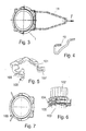
- An inventive clip 1, as shown in Figures 1 to 4 is used in particular for connecting two tubes 2 and 3 or one Pipe with a connection of a motor vehicle heat exchanger.
- this connection is - according to the prior art - one of the tubes 2 at his End provided with a first flange 4, the other, in the first tube. 2 easily inserted second tube 3 is slightly spaced from its end with a circumferential flange forming a second flange 5 is provided has a smaller outer diameter than the first flange 4.
- the bracket 1 is substantially symmetrical with respect to the transverse axis educated.
- the transverse axis runs parallel when installed to the longitudinal axis of the pipes to be connected and secured 2, 3.
- the clip 1 has a plurality of tabs 6, which are bent over and for positioning and fixing the tubes 2, 3 serve.
- the end portion 8 of the bracket 1 is, as shown in Fig. 4 can be seen, bent back.
- the end region 8 forms approximately the shape of a rounded, right triangle.
- the slot 7 extends over two of the three Triangular sides and ends approximately in the radially outermost corner.
- the end 10 of the bracket 1 is bent so far that it with an edge on Flange 4 is applied (see Fig. 3).
- the edge is sharp-edged, so that when assembling it to plastic deformation of the flange 4 can come and the bracket 1 "bites".
- edges of the clip 1 are rounded for better handling.
- the tubes 2 and 3 are positioned and the Clamp 1 pushed over it like a clip.
- the peel force controlled.
Landscapes
- Engineering & Computer Science (AREA)
- General Engineering & Computer Science (AREA)
- Mechanical Engineering (AREA)
- Clamps And Clips (AREA)
- Supports For Pipes And Cables (AREA)
- Flanged Joints, Insulating Joints, And Other Joints (AREA)
- Mutual Connection Of Rods And Tubes (AREA)
Abstract
Description
- Fig. 1
- eine Ansicht einer erfindungsgemäßen Klammer,
- Fig. 2
- eine Ansicht der Klammer von Fig. 1 in eingebautem Zustand,
- Fig. 3
- eine vereinfacht dargestellte Draufsicht auf die eingebaute Klammer entsprechend Fig. 2,
- Fig. 4
- eine mittig geschnitten dargestellte Detailansicht der Klammer von Fig. 1,
- Fig. 5
- eine Klammer gemäß dem Stand der Technik in einer Fig. 1 entsprechenden Ansicht,
- Fig. 6
- eine Ansicht der herkömmlichen Klammer von Fig. 5 in eingebautem Zustand, und
- Fig. 7
- eine vereinfacht dargestellte Draufsicht auf die eingebaute, herkömmliche Klammer entsprechend Fig. 6.
- 1, 101
- Klammer
- 2, 102
- Rohr
- 3, 103
- Rohr
- 4, 104
- Flansch
- 5, 105
- Flansch
- 6,
- Lasche
- 7, 107
- Schlitz
- 8, 108
- Endbereich
- 9, 109
- Einfuhrschräge
- 10
- Ende
- 11
- Ziehdorn
Claims (12)
- Klammer zur Befestigung und Verbindung von Rohren (2, 3), insbesondere zur Befestigung eines Anschlussrohrs an einem Wärmetauscher in einem Kraftfahrzeug, dadurch gekennzeichnet, dass zumindest ein Endbereich (8) der Klammer (1) zurückgebogen ist.
- Klammer nach Anspruch 1, dadurch gekennzeichnet, dass der zurückgebogene Endbereich (8) der Klammer (1) zumindest eine scharfkantige Kante aufweist.
- Klammer nach Anspruch 1 oder 2, dadurch gekennzeichnet, dass der zurückgebogene Endbereich (8) im zusammengebauten Zustand in Anlage an zumindest einen Flansch (4) oder Wulst eines Rohres (2) ist.
- Klammer nach Anspruch 3, dadurch gekennzeichnet, dass der zurückgebogene Endbereich im Bereich der Anlage scharfkantig ausgebildet ist.
- Klammer nach einem der vorhergehenden Ansprüche, dadurch gekennzeichnet, dass maximal eine im zusammengebauten Zustand in radialer Richtung nach außen abstehende Lasche (6) an der Klammer (1) vorgesehen ist.
- Klammer nach Anspruch 5, dadurch gekennzeichnet, dass keine abstehende Lasche an der Klammer (1) vorgesehen ist.
- Klammer nach einem der vorhergehenden Ansprüche, dadurch gekennzeichnet, dass die Endbereiche (8) der Klammer (1) derart zurückgebogen sind, dass sie annähernd die Form eines abgerundeten Dreiecks bilden.
- Klammer nach Anspruch 7, dadurch gekennzeichnet, dass die Dreiecke keinen Winkel über 90° aufweisen.
- Klammer nach Anspruch 7 oder 8, dadurch gekennzeichnet, dass die Dreiecke annähernd gleichseitig sind.
- Klammer nach einem der vorhergehenden Ansprüche, dadurch gekennzeichnet, dass ein Schlitz (7) im Bereich mindestens eines Endbereichs (8) der Klammer (1) vorgesehen ist, der in Längsrichtung der Klammer (1) verläuft.
- Klammer nach Anspruch 7 und 10, dadurch gekennzeichnet, dass der Schlitz (7) über zwei Seiten des entsprechenden Dreiecks verläuft.
- Klammer nach einem der vorstehenden Ansprüche, dadurch gekennzeichnet, dass die Klammer (1) im wesentlichen symmetrisch bezüglich einer Querachse ausgebildet ist.
Priority Applications (11)
| Application Number | Priority Date | Filing Date | Title |
|---|---|---|---|
| DE50209676T DE50209676D1 (de) | 2002-12-14 | 2002-12-14 | Klammer zur Befestigung und Verbindung von Rohren |
| AT02027991T ATE356311T1 (de) | 2002-12-14 | 2002-12-14 | Klammer zur befestigung und verbindung von rohren |
| ES02027991T ES2282364T3 (es) | 2002-12-14 | 2002-12-14 | Abrazadera para la fijacion y la conexion de tubos. |
| EP02027991A EP1429066B1 (de) | 2002-12-14 | 2002-12-14 | Klammer zur Befestigung und Verbindung von Rohren |
| JP2004559687A JP4550588B2 (ja) | 2002-12-14 | 2003-11-14 | 管を固定して結合するためのクランプ |
| BRPI0317252-0A BR0317252B1 (pt) | 2002-12-14 | 2003-11-14 | Braçadeira para fixar e conectar tubos |
| CA002508444A CA2508444A1 (en) | 2002-12-14 | 2003-11-14 | Clamp for fastening and connecting tubes |
| PCT/EP2003/012729 WO2004055424A1 (de) | 2002-12-14 | 2003-11-14 | Klammer zur befestigung und verbindung von rohren |
| US10/538,884 US7445253B2 (en) | 2002-12-14 | 2003-11-14 | Clamp for fastening and connecting tubes |
| AU2003288062A AU2003288062A1 (en) | 2002-12-14 | 2003-11-14 | Clamp for fastening and connecting tubes |
| CNB2003801060917A CN100414161C (zh) | 2002-12-14 | 2003-11-14 | 用于固定和连接管子的管夹 |
Applications Claiming Priority (1)
| Application Number | Priority Date | Filing Date | Title |
|---|---|---|---|
| EP02027991A EP1429066B1 (de) | 2002-12-14 | 2002-12-14 | Klammer zur Befestigung und Verbindung von Rohren |
Publications (2)
| Publication Number | Publication Date |
|---|---|
| EP1429066A1 true EP1429066A1 (de) | 2004-06-16 |
| EP1429066B1 EP1429066B1 (de) | 2007-03-07 |
Family
ID=32319608
Family Applications (1)
| Application Number | Title | Priority Date | Filing Date |
|---|---|---|---|
| EP02027991A Expired - Lifetime EP1429066B1 (de) | 2002-12-14 | 2002-12-14 | Klammer zur Befestigung und Verbindung von Rohren |
Country Status (11)
| Country | Link |
|---|---|
| US (1) | US7445253B2 (de) |
| EP (1) | EP1429066B1 (de) |
| JP (1) | JP4550588B2 (de) |
| CN (1) | CN100414161C (de) |
| AT (1) | ATE356311T1 (de) |
| AU (1) | AU2003288062A1 (de) |
| BR (1) | BR0317252B1 (de) |
| CA (1) | CA2508444A1 (de) |
| DE (1) | DE50209676D1 (de) |
| ES (1) | ES2282364T3 (de) |
| WO (1) | WO2004055424A1 (de) |
Cited By (3)
| Publication number | Priority date | Publication date | Assignee | Title |
|---|---|---|---|---|
| WO2006037404A1 (de) * | 2004-10-06 | 2006-04-13 | A. Raymond Et Cie | Vorrichtung zum verbinden von rohrenden |
| WO2007147510A1 (de) * | 2006-06-22 | 2007-12-27 | A. Raymond Et Cie | Manschette zum verbinden von zwei jeweils mit einem abschlusskragen ausgebildeten rohren |
| US20250224061A1 (en) * | 2024-01-05 | 2025-07-10 | Phinia Jersey Holdings Llc | Quick-connect clip assembly for an evaporative emissions canister port |
Families Citing this family (8)
| Publication number | Priority date | Publication date | Assignee | Title |
|---|---|---|---|---|
| US5888981A (en) | 1993-06-14 | 1999-03-30 | Basf Aktiengesellschaft | Methods for regulating gene expression |
| US8087703B2 (en) * | 2007-04-20 | 2012-01-03 | Piolax Inc. | Component connecting structure |
| KR101251981B1 (ko) * | 2011-12-05 | 2013-04-08 | 주식회사 대동시스템 | 자동차 케이블 지지클립 |
| KR200471458Y1 (ko) | 2012-04-26 | 2014-02-25 | 이호영 | 파이프용 클램프 |
| CN103711755B (zh) * | 2013-12-26 | 2016-05-11 | 葫芦岛天力工业有限公司 | 鱼雷锁固环 |
| CN103834949B (zh) * | 2014-02-24 | 2016-03-30 | 青岛钢研纳克检测防护技术有限公司 | 一种多功能快速安装卡箍及其使用方法 |
| USD1002358S1 (en) * | 2021-01-20 | 2023-10-24 | Ubicquia, Inc. | Pole clamp |
| USD1083579S1 (en) * | 2021-01-20 | 2025-07-15 | Ubicquia, Inc. | Camera system |
Citations (5)
| Publication number | Priority date | Publication date | Assignee | Title |
|---|---|---|---|---|
| FR2188779A5 (de) * | 1972-06-13 | 1974-01-18 | Citroen Sa | |
| FR2360028A1 (fr) * | 1976-07-30 | 1978-02-24 | Peugeot Cycles | Articulation pour tuyau et notamment pour tuyau d'echappement de vehicule automobile |
| DE3026221A1 (de) * | 1980-07-10 | 1982-02-04 | Hilti AG, 9494 Schaan | Befestigungseinrichtung zum abhaengen von rohren u.dgl. gegenstaenden an decken |
| US4913468A (en) * | 1989-04-13 | 1990-04-03 | Eaton Corporation | Tube union reinforcing clip |
| DE19953129A1 (de) * | 1999-11-04 | 2001-05-10 | Behr Gmbh & Co | Rohranschluß für einen Wärmeübertrager eines Kraftfahrzeuges |
Family Cites Families (14)
| Publication number | Priority date | Publication date | Assignee | Title |
|---|---|---|---|---|
| CH370604A (fr) * | 1961-09-14 | 1963-07-15 | Lapidor Sa | Dispositif d'assemblage d'éléments tubulaires, notamment pour la réalisation de canaux de ventilation |
| US3479069A (en) * | 1967-10-20 | 1969-11-18 | Amseco Corp | Connector assembly |
| SU666363A1 (ru) * | 1977-12-28 | 1979-06-05 | Предприятие П/Я А-3395 | Устройство дл соединени трубопроводов |
| US4463975A (en) * | 1982-01-27 | 1984-08-07 | Garlock, Inc. | Band seal clamp |
| US4461499A (en) * | 1983-03-23 | 1984-07-24 | Industrial Air, Inc. | Transverse joint system for sheet metal ducts |
| US5348353A (en) * | 1993-12-02 | 1994-09-20 | Chrysler Corporation | Positive quick-connect tube locking construction with preassembly retention of spring keeper |
| FR2751722B1 (fr) * | 1996-07-24 | 1998-09-18 | Bundy | Dispositif de fixation destine a assujettir un organe de jonction de tubes a une plaquette qu'il traverse par une ouverture associee |
| JP3765336B2 (ja) * | 1996-10-15 | 2006-04-12 | 株式会社デンソー | 燃料供給装置およびその製造方法 |
| DE19728973A1 (de) * | 1997-07-07 | 1999-01-14 | Bauer Christian Gmbh & Co | Federeinrichtung zum Verbinden zweier Flansche |
| DE19752280A1 (de) * | 1997-11-26 | 1999-06-02 | Daimler Benz Ag | Vorrichtung zum Verbinden von zwei rohrförmigen Leitungsteilen |
| US6053149A (en) * | 1998-05-28 | 2000-04-25 | Siemens Automotive Corporation | Fuel injector clip retention arrangement |
| US6874477B1 (en) * | 1999-04-20 | 2005-04-05 | Siemens Vdo Automotive Corp. | Fuel injector mounting arrangement |
| DE10015028C1 (de) * | 2000-03-25 | 2001-09-27 | Guenther Ebinger | Einstückige, aus Federstahlblech gebogene Steckklammer für Flanschverbindungen |
| US6481420B2 (en) * | 2001-01-30 | 2002-11-19 | Visteon Global Technologies, Inc. | Method and apparatus for maintaining the alignment of a fuel injector |
-
2002
- 2002-12-14 EP EP02027991A patent/EP1429066B1/de not_active Expired - Lifetime
- 2002-12-14 ES ES02027991T patent/ES2282364T3/es not_active Expired - Lifetime
- 2002-12-14 DE DE50209676T patent/DE50209676D1/de not_active Expired - Lifetime
- 2002-12-14 AT AT02027991T patent/ATE356311T1/de not_active IP Right Cessation
-
2003
- 2003-11-14 CA CA002508444A patent/CA2508444A1/en not_active Abandoned
- 2003-11-14 BR BRPI0317252-0A patent/BR0317252B1/pt not_active IP Right Cessation
- 2003-11-14 JP JP2004559687A patent/JP4550588B2/ja not_active Expired - Fee Related
- 2003-11-14 US US10/538,884 patent/US7445253B2/en not_active Expired - Lifetime
- 2003-11-14 WO PCT/EP2003/012729 patent/WO2004055424A1/de not_active Ceased
- 2003-11-14 CN CNB2003801060917A patent/CN100414161C/zh not_active Expired - Fee Related
- 2003-11-14 AU AU2003288062A patent/AU2003288062A1/en not_active Abandoned
Patent Citations (5)
| Publication number | Priority date | Publication date | Assignee | Title |
|---|---|---|---|---|
| FR2188779A5 (de) * | 1972-06-13 | 1974-01-18 | Citroen Sa | |
| FR2360028A1 (fr) * | 1976-07-30 | 1978-02-24 | Peugeot Cycles | Articulation pour tuyau et notamment pour tuyau d'echappement de vehicule automobile |
| DE3026221A1 (de) * | 1980-07-10 | 1982-02-04 | Hilti AG, 9494 Schaan | Befestigungseinrichtung zum abhaengen von rohren u.dgl. gegenstaenden an decken |
| US4913468A (en) * | 1989-04-13 | 1990-04-03 | Eaton Corporation | Tube union reinforcing clip |
| DE19953129A1 (de) * | 1999-11-04 | 2001-05-10 | Behr Gmbh & Co | Rohranschluß für einen Wärmeübertrager eines Kraftfahrzeuges |
Cited By (5)
| Publication number | Priority date | Publication date | Assignee | Title |
|---|---|---|---|---|
| WO2006037404A1 (de) * | 2004-10-06 | 2006-04-13 | A. Raymond Et Cie | Vorrichtung zum verbinden von rohrenden |
| WO2007147510A1 (de) * | 2006-06-22 | 2007-12-27 | A. Raymond Et Cie | Manschette zum verbinden von zwei jeweils mit einem abschlusskragen ausgebildeten rohren |
| US7789436B2 (en) | 2006-06-22 | 2010-09-07 | A. Raymond Et Cie | Collar for joining two pipes comprising one respective connecting neck |
| US20250224061A1 (en) * | 2024-01-05 | 2025-07-10 | Phinia Jersey Holdings Llc | Quick-connect clip assembly for an evaporative emissions canister port |
| US12422072B2 (en) * | 2024-01-05 | 2025-09-23 | Phinia Jersey Holdings Llc | Quick-connect clip assembly for an evaporative emissions canister port |
Also Published As
| Publication number | Publication date |
|---|---|
| EP1429066B1 (de) | 2007-03-07 |
| AU2003288062A1 (en) | 2004-07-09 |
| ATE356311T1 (de) | 2007-03-15 |
| BR0317252A (pt) | 2005-11-01 |
| BR0317252B1 (pt) | 2015-01-27 |
| JP2006509978A (ja) | 2006-03-23 |
| US7445253B2 (en) | 2008-11-04 |
| CN100414161C (zh) | 2008-08-27 |
| JP4550588B2 (ja) | 2010-09-22 |
| CA2508444A1 (en) | 2004-07-01 |
| CN1726367A (zh) | 2006-01-25 |
| AU2003288062A8 (en) | 2004-07-09 |
| ES2282364T3 (es) | 2007-10-16 |
| US20060066103A1 (en) | 2006-03-30 |
| DE50209676D1 (de) | 2007-04-19 |
| WO2004055424A1 (de) | 2004-07-01 |
Similar Documents
| Publication | Publication Date | Title |
|---|---|---|
| EP0750152B1 (de) | Steckverbindung für den Anschluss von Rohr- und Schlauchleitungen | |
| EP0675311B1 (de) | Rohrschellenverschluss | |
| DE3017666C2 (de) | ||
| DE19650675C2 (de) | Profilschelle | |
| DE2802109C2 (de) | Bohrloch-Zentrierstück, Manschettenhälfte dafür und Verfahren zur Herstellung eines solchen Zentrierstücks | |
| DE3017178C2 (de) | Schraublose Klemmschelle | |
| EP3423743B1 (de) | Profilschelle mit dichtelement und leitungsverbindungsanordnung mit einer derartigen profilschelle | |
| EP0196442A2 (de) | Rohrschelle | |
| DE102017108586B3 (de) | Scharnier für ein Schaltschrankgehäuse sowie ein entsprechendes Schaltschrankgehäuse und Montageverfahren | |
| EP0828106B1 (de) | Federbandschelle | |
| CH670869A5 (de) | ||
| EP1429066B1 (de) | Klammer zur Befestigung und Verbindung von Rohren | |
| WO2017149104A1 (de) | Vorpositionierer für eine profilschelle und verbindungsanordnung mit einem derartigen vorpositionierer | |
| DE3122656C1 (de) | Schraublose Klemmschelle | |
| DE10084668B4 (de) | Klemmschelle | |
| EP3500786B1 (de) | Sicherungskralle | |
| EP2872808B1 (de) | Rohrschelle | |
| EP2041469A1 (de) | Gehäuse für rohrkupplung | |
| DE102009024813A1 (de) | Befestigungsschelle | |
| DE4127017C1 (en) | Hose clip with clamping strip and radial spring - which is integrally formed with clamping strip lug | |
| DE102010013159A1 (de) | Steckverbindung | |
| EP1067336A1 (de) | Abstandshalter für ein Kamin-Rauchrohr | |
| DE19953129B4 (de) | Rohranschluß für einen Wärmeübertrager eines Kraftfahrzeuges | |
| EP4493849A1 (de) | Profilschelle | |
| EP1239207B1 (de) | Federbandelement |
Legal Events
| Date | Code | Title | Description |
|---|---|---|---|
| PUAI | Public reference made under article 153(3) epc to a published international application that has entered the european phase |
Free format text: ORIGINAL CODE: 0009012 |
|
| AK | Designated contracting states |
Kind code of ref document: A1 Designated state(s): AT BE BG CH CY CZ DE DK EE ES FI FR GB GR IE IT LI LU MC NL PT SE SI SK TR |
|
| AX | Request for extension of the european patent |
Extension state: AL LT LV MK RO |
|
| 17P | Request for examination filed |
Effective date: 20041216 |
|
| AKX | Designation fees paid |
Designated state(s): AT BE BG CH CY CZ DE DK EE ES FI FR GB GR IE IT LI LU MC NL PT SE SI SK TR |
|
| 17Q | First examination report despatched |
Effective date: 20050304 |
|
| RAP1 | Party data changed (applicant data changed or rights of an application transferred) |
Owner name: BEHR FRANCE ROUFFACH SAS Owner name: BEHR GMBH & CO. KG |
|
| GRAP | Despatch of communication of intention to grant a patent |
Free format text: ORIGINAL CODE: EPIDOSNIGR1 |
|
| GRAS | Grant fee paid |
Free format text: ORIGINAL CODE: EPIDOSNIGR3 |
|
| GRAA | (expected) grant |
Free format text: ORIGINAL CODE: 0009210 |
|
| AK | Designated contracting states |
Kind code of ref document: B1 Designated state(s): AT BE BG CH CY CZ DE DK EE ES FI FR GB GR IE IT LI LU MC NL PT SE SI SK TR |
|
| PG25 | Lapsed in a contracting state [announced via postgrant information from national office to epo] |
Ref country code: NL Free format text: LAPSE BECAUSE OF FAILURE TO SUBMIT A TRANSLATION OF THE DESCRIPTION OR TO PAY THE FEE WITHIN THE PRESCRIBED TIME-LIMIT Effective date: 20070307 Ref country code: FI Free format text: LAPSE BECAUSE OF FAILURE TO SUBMIT A TRANSLATION OF THE DESCRIPTION OR TO PAY THE FEE WITHIN THE PRESCRIBED TIME-LIMIT Effective date: 20070307 Ref country code: SI Free format text: LAPSE BECAUSE OF FAILURE TO SUBMIT A TRANSLATION OF THE DESCRIPTION OR TO PAY THE FEE WITHIN THE PRESCRIBED TIME-LIMIT Effective date: 20070307 Ref country code: IE Free format text: LAPSE BECAUSE OF FAILURE TO SUBMIT A TRANSLATION OF THE DESCRIPTION OR TO PAY THE FEE WITHIN THE PRESCRIBED TIME-LIMIT Effective date: 20070307 |
|
| REG | Reference to a national code |
Ref country code: GB Ref legal event code: FG4D Free format text: NOT ENGLISH |
|
| REG | Reference to a national code |
Ref country code: CH Ref legal event code: EP |
|
| REF | Corresponds to: |
Ref document number: 50209676 Country of ref document: DE Date of ref document: 20070419 Kind code of ref document: P |
|
| REG | Reference to a national code |
Ref country code: IE Ref legal event code: FG4D Free format text: LANGUAGE OF EP DOCUMENT: GERMAN |
|
| PG25 | Lapsed in a contracting state [announced via postgrant information from national office to epo] |
Ref country code: SE Free format text: LAPSE BECAUSE OF FAILURE TO SUBMIT A TRANSLATION OF THE DESCRIPTION OR TO PAY THE FEE WITHIN THE PRESCRIBED TIME-LIMIT Effective date: 20070607 |
|
| PG25 | Lapsed in a contracting state [announced via postgrant information from national office to epo] |
Ref country code: PT Free format text: LAPSE BECAUSE OF FAILURE TO SUBMIT A TRANSLATION OF THE DESCRIPTION OR TO PAY THE FEE WITHIN THE PRESCRIBED TIME-LIMIT Effective date: 20070807 |
|
| NLV1 | Nl: lapsed or annulled due to failure to fulfill the requirements of art. 29p and 29m of the patents act | ||
| GBV | Gb: ep patent (uk) treated as always having been void in accordance with gb section 77(7)/1977 [no translation filed] |
Effective date: 20070307 |
|
| REG | Reference to a national code |
Ref country code: ES Ref legal event code: FG2A Ref document number: 2282364 Country of ref document: ES Kind code of ref document: T3 |
|
| REG | Reference to a national code |
Ref country code: IE Ref legal event code: FD4D |
|
| PG25 | Lapsed in a contracting state [announced via postgrant information from national office to epo] |
Ref country code: SK Free format text: LAPSE BECAUSE OF FAILURE TO SUBMIT A TRANSLATION OF THE DESCRIPTION OR TO PAY THE FEE WITHIN THE PRESCRIBED TIME-LIMIT Effective date: 20070307 Ref country code: GB Free format text: LAPSE BECAUSE OF FAILURE TO SUBMIT A TRANSLATION OF THE DESCRIPTION OR TO PAY THE FEE WITHIN THE PRESCRIBED TIME-LIMIT Effective date: 20070307 |
|
| PLBE | No opposition filed within time limit |
Free format text: ORIGINAL CODE: 0009261 |
|
| STAA | Information on the status of an ep patent application or granted ep patent |
Free format text: STATUS: NO OPPOSITION FILED WITHIN TIME LIMIT |
|
| PG25 | Lapsed in a contracting state [announced via postgrant information from national office to epo] |
Ref country code: DK Free format text: LAPSE BECAUSE OF FAILURE TO SUBMIT A TRANSLATION OF THE DESCRIPTION OR TO PAY THE FEE WITHIN THE PRESCRIBED TIME-LIMIT Effective date: 20070307 |
|
| 26N | No opposition filed |
Effective date: 20071210 |
|
| PG25 | Lapsed in a contracting state [announced via postgrant information from national office to epo] |
Ref country code: GR Free format text: LAPSE BECAUSE OF FAILURE TO SUBMIT A TRANSLATION OF THE DESCRIPTION OR TO PAY THE FEE WITHIN THE PRESCRIBED TIME-LIMIT Effective date: 20070608 |
|
| BERE | Be: lapsed |
Owner name: BEHR FRANCE ROUFFACH SAS Effective date: 20071231 Owner name: BEHR G.M.B.H. & CO. KG Effective date: 20071231 |
|
| PG25 | Lapsed in a contracting state [announced via postgrant information from national office to epo] |
Ref country code: MC Free format text: LAPSE BECAUSE OF NON-PAYMENT OF DUE FEES Effective date: 20071231 |
|
| REG | Reference to a national code |
Ref country code: CH Ref legal event code: PL |
|
| PG25 | Lapsed in a contracting state [announced via postgrant information from national office to epo] |
Ref country code: BE Free format text: LAPSE BECAUSE OF NON-PAYMENT OF DUE FEES Effective date: 20071231 |
|
| PG25 | Lapsed in a contracting state [announced via postgrant information from national office to epo] |
Ref country code: LI Free format text: LAPSE BECAUSE OF NON-PAYMENT OF DUE FEES Effective date: 20071231 Ref country code: CH Free format text: LAPSE BECAUSE OF NON-PAYMENT OF DUE FEES Effective date: 20071231 |
|
| PG25 | Lapsed in a contracting state [announced via postgrant information from national office to epo] |
Ref country code: EE Free format text: LAPSE BECAUSE OF FAILURE TO SUBMIT A TRANSLATION OF THE DESCRIPTION OR TO PAY THE FEE WITHIN THE PRESCRIBED TIME-LIMIT Effective date: 20070307 |
|
| PG25 | Lapsed in a contracting state [announced via postgrant information from national office to epo] |
Ref country code: AT Free format text: LAPSE BECAUSE OF NON-PAYMENT OF DUE FEES Effective date: 20071214 |
|
| PG25 | Lapsed in a contracting state [announced via postgrant information from national office to epo] |
Ref country code: CY Free format text: LAPSE BECAUSE OF FAILURE TO SUBMIT A TRANSLATION OF THE DESCRIPTION OR TO PAY THE FEE WITHIN THE PRESCRIBED TIME-LIMIT Effective date: 20070307 |
|
| PG25 | Lapsed in a contracting state [announced via postgrant information from national office to epo] |
Ref country code: BG Free format text: LAPSE BECAUSE OF FAILURE TO SUBMIT A TRANSLATION OF THE DESCRIPTION OR TO PAY THE FEE WITHIN THE PRESCRIBED TIME-LIMIT Effective date: 20070607 Ref country code: LU Free format text: LAPSE BECAUSE OF NON-PAYMENT OF DUE FEES Effective date: 20071214 |
|
| PG25 | Lapsed in a contracting state [announced via postgrant information from national office to epo] |
Ref country code: TR Free format text: LAPSE BECAUSE OF FAILURE TO SUBMIT A TRANSLATION OF THE DESCRIPTION OR TO PAY THE FEE WITHIN THE PRESCRIBED TIME-LIMIT Effective date: 20070307 |
|
| PGFP | Annual fee paid to national office [announced via postgrant information from national office to epo] |
Ref country code: CZ Payment date: 20101214 Year of fee payment: 9 |
|
| PGFP | Annual fee paid to national office [announced via postgrant information from national office to epo] |
Ref country code: IT Payment date: 20101217 Year of fee payment: 9 |
|
| PGFP | Annual fee paid to national office [announced via postgrant information from national office to epo] |
Ref country code: ES Payment date: 20101222 Year of fee payment: 9 |
|
| PG25 | Lapsed in a contracting state [announced via postgrant information from national office to epo] |
Ref country code: CZ Free format text: LAPSE BECAUSE OF NON-PAYMENT OF DUE FEES Effective date: 20111214 |
|
| PG25 | Lapsed in a contracting state [announced via postgrant information from national office to epo] |
Ref country code: IT Free format text: LAPSE BECAUSE OF NON-PAYMENT OF DUE FEES Effective date: 20111214 |
|
| REG | Reference to a national code |
Ref country code: ES Ref legal event code: FD2A Effective date: 20131023 |
|
| PG25 | Lapsed in a contracting state [announced via postgrant information from national office to epo] |
Ref country code: ES Free format text: LAPSE BECAUSE OF NON-PAYMENT OF DUE FEES Effective date: 20111215 |
|
| REG | Reference to a national code |
Ref country code: DE Ref legal event code: R082 Ref document number: 50209676 Country of ref document: DE Representative=s name: GRAUEL, ANDREAS, DIPL.-PHYS. DR. RER. NAT., DE Ref country code: DE Ref legal event code: R081 Ref document number: 50209676 Country of ref document: DE Owner name: MAHLE INTERNATIONAL GMBH, DE Free format text: FORMER OWNERS: BEHR GMBH & CO. KG, 70469 STUTTGART, DE; BEHR FRANCE ROUFFACH S.A.S., ROUFFACH, FR |
|
| REG | Reference to a national code |
Ref country code: FR Ref legal event code: PLFP Year of fee payment: 14 |
|
| REG | Reference to a national code |
Ref country code: FR Ref legal event code: PLFP Year of fee payment: 15 |
|
| REG | Reference to a national code |
Ref country code: FR Ref legal event code: PLFP Year of fee payment: 16 |
|
| PGFP | Annual fee paid to national office [announced via postgrant information from national office to epo] |
Ref country code: FR Payment date: 20181221 Year of fee payment: 17 |
|
| PGFP | Annual fee paid to national office [announced via postgrant information from national office to epo] |
Ref country code: DE Payment date: 20200220 Year of fee payment: 18 |
|
| PG25 | Lapsed in a contracting state [announced via postgrant information from national office to epo] |
Ref country code: FR Free format text: LAPSE BECAUSE OF NON-PAYMENT OF DUE FEES Effective date: 20191231 |
|
| REG | Reference to a national code |
Ref country code: DE Ref legal event code: R119 Ref document number: 50209676 Country of ref document: DE |
|
| PG25 | Lapsed in a contracting state [announced via postgrant information from national office to epo] |
Ref country code: DE Free format text: LAPSE BECAUSE OF NON-PAYMENT OF DUE FEES Effective date: 20210701 |