EP1428971B1 - Spannanordnungsvorrichtung mit integriertem Druckmittelspeicher - Google Patents
Spannanordnungsvorrichtung mit integriertem Druckmittelspeicher Download PDFInfo
- Publication number
- EP1428971B1 EP1428971B1 EP03257691A EP03257691A EP1428971B1 EP 1428971 B1 EP1428971 B1 EP 1428971B1 EP 03257691 A EP03257691 A EP 03257691A EP 03257691 A EP03257691 A EP 03257691A EP 1428971 B1 EP1428971 B1 EP 1428971B1
- Authority
- EP
- European Patent Office
- Prior art keywords
- cylinder
- ram
- hydraulic fluid
- wall surface
- cavity
- Prior art date
- Legal status (The legal status is an assumption and is not a legal conclusion. Google has not performed a legal analysis and makes no representation as to the accuracy of the status listed.)
- Expired - Lifetime
Links
- 239000012530 fluid Substances 0.000 title claims abstract description 167
- 238000012546 transfer Methods 0.000 claims abstract description 32
- 238000004891 communication Methods 0.000 claims description 44
- 238000004519 manufacturing process Methods 0.000 abstract description 9
- 238000007667 floating Methods 0.000 abstract description 5
- 230000033001 locomotion Effects 0.000 abstract description 4
- 230000006835 compression Effects 0.000 abstract description 2
- 238000007906 compression Methods 0.000 abstract description 2
- 239000007789 gas Substances 0.000 description 29
- 238000005553 drilling Methods 0.000 description 13
- 230000000712 assembly Effects 0.000 description 12
- 238000000429 assembly Methods 0.000 description 12
- 238000000034 method Methods 0.000 description 4
- 238000013461 design Methods 0.000 description 3
- 239000000463 material Substances 0.000 description 3
- 238000012986 modification Methods 0.000 description 3
- 230000004048 modification Effects 0.000 description 3
- XLYOFNOQVPJJNP-UHFFFAOYSA-N water Substances O XLYOFNOQVPJJNP-UHFFFAOYSA-N 0.000 description 3
- IJGRMHOSHXDMSA-UHFFFAOYSA-N Atomic nitrogen Chemical compound N#N IJGRMHOSHXDMSA-UHFFFAOYSA-N 0.000 description 2
- 238000010276 construction Methods 0.000 description 2
- 238000011161 development Methods 0.000 description 2
- 238000005516 engineering process Methods 0.000 description 2
- 229910000975 Carbon steel Inorganic materials 0.000 description 1
- RTAQQCXQSZGOHL-UHFFFAOYSA-N Titanium Chemical compound [Ti] RTAQQCXQSZGOHL-UHFFFAOYSA-N 0.000 description 1
- 229910052782 aluminium Inorganic materials 0.000 description 1
- XAGFODPZIPBFFR-UHFFFAOYSA-N aluminium Chemical compound [Al] XAGFODPZIPBFFR-UHFFFAOYSA-N 0.000 description 1
- 230000004888 barrier function Effects 0.000 description 1
- 239000010962 carbon steel Substances 0.000 description 1
- 230000007797 corrosion Effects 0.000 description 1
- 238000005260 corrosion Methods 0.000 description 1
- 230000009977 dual effect Effects 0.000 description 1
- 238000005868 electrolysis reaction Methods 0.000 description 1
- 230000008014 freezing Effects 0.000 description 1
- 238000007710 freezing Methods 0.000 description 1
- ZZUFCTLCJUWOSV-UHFFFAOYSA-N furosemide Chemical compound C1=C(Cl)C(S(=O)(=O)N)=CC(C(O)=O)=C1NCC1=CC=CO1 ZZUFCTLCJUWOSV-UHFFFAOYSA-N 0.000 description 1
- 210000004907 gland Anatomy 0.000 description 1
- 238000009434 installation Methods 0.000 description 1
- 239000003562 lightweight material Substances 0.000 description 1
- 229910052751 metal Inorganic materials 0.000 description 1
- 239000002184 metal Substances 0.000 description 1
- 229910052757 nitrogen Inorganic materials 0.000 description 1
- 230000000630 rising effect Effects 0.000 description 1
- 238000000926 separation method Methods 0.000 description 1
- 239000010935 stainless steel Substances 0.000 description 1
- 229910001220 stainless steel Inorganic materials 0.000 description 1
- 239000010936 titanium Substances 0.000 description 1
- 229910052719 titanium Inorganic materials 0.000 description 1
- 238000003466 welding Methods 0.000 description 1
Images

Classifications
-
- E—FIXED CONSTRUCTIONS
- E21—EARTH OR ROCK DRILLING; MINING
- E21B—EARTH OR ROCK DRILLING; OBTAINING OIL, GAS, WATER, SOLUBLE OR MELTABLE MATERIALS OR A SLURRY OF MINERALS FROM WELLS
- E21B19/00—Handling rods, casings, tubes or the like outside the borehole, e.g. in the derrick; Apparatus for feeding the rods or cables
- E21B19/002—Handling rods, casings, tubes or the like outside the borehole, e.g. in the derrick; Apparatus for feeding the rods or cables specially adapted for underwater drilling
- E21B19/004—Handling rods, casings, tubes or the like outside the borehole, e.g. in the derrick; Apparatus for feeding the rods or cables specially adapted for underwater drilling supporting a riser from a drilling or production platform
- E21B19/006—Handling rods, casings, tubes or the like outside the borehole, e.g. in the derrick; Apparatus for feeding the rods or cables specially adapted for underwater drilling supporting a riser from a drilling or production platform including heave compensators
Definitions
- the invention relates to tensioning devices for exerting a tensile force from a drilling vessel or drilling platform upon a drilling or production riser.
- a marine riser system is employed to provide a conduit from a floating vessel at the water surface to the blowout preventer stack or, production tree, which is connected to the wellhead at the sea floor.
- a tensioner, or motion compensator is incorporated into the riser string to compensate for vessel motion induced by wave action and heave.
- a tensioning system is utilized to maintain a variable tension to the riser string alleviating the potential for compression and in turn buckling or failure.
- the number of tensioner units employed is based on the tension necessary to maintain support of the riser and a percentage of overpull which is dictated by met-ocean conditions i.e., current and operational parameters including variable mud weight, etc.
- the tensioner assemblies of the present invention offer operational advantages over conventional methodologies by providing options in riser management and current well construction techniques.
- Applications of the basic module design are not limited to drilling risers and floating drilling vessels.
- the system further provides cost and operational effective solutions in well servicing/workover, intervention and production riser applications. These applications include all floating production facilities including, tension leg platform, floating production facility, and production spar variants.
- the system when installed provides an effective solution to tensioning requirements and operating parameters.
- An integral control and data acquisition system provides operating parameters to a central processor system which provides supervisory control.
- tensioner assemblies are of two types, the piston type and the ram type.
- the piston type cylinder With the piston type cylinder, the rod is stroked out by pressured hydraulic fluid which is stored in an external accumulator charged with high pressure air. The hydraulic fluid flows into the cylinder from an external accumulator and the pressurized hydraulic fluid acts on the piston to extend the rod.
- the piston has a pressure barrier seal between the piston and the inner wall of the cylinder. When the rod is retracted the hydraulic fluid is displaced by the piston and rod flowing back into the external accumulator.
- Prior ram-type tensioner assemblies include a ram, which is sealed around its outer diameter to the upper gland of the cylinder. As the pressurized hydraulic fluid flows into the cylinder from the external accumulator the ram extends. When the ram retracts, the hydraulic fluid is displaced back into the external accumulator. Therefore, these prior tensioner assemblies require the hydraulic fluid volume to be displaced by the piston or ram, which then flows back into the external accumulator.
- the present invention is directed to ram-type tensioner assemblies in which the hydraulic fluid accumulator is integral with the cylinder and the ram and which includes an air transfer tube disposed within the cylinder cavity and the ram cavity to provide an air over hydraulic fluid arrangement.
- the tensioner assemblies of the present invention provide the advantage of reducing the amount of deck space required for each tensioner assembly because external hydraulic fluid accumulators are not necessary.
- the tensioner assemblies of the present invention also provide that the volume occupied by the wall thickness of the ram displaces the hydraulic fluid. This results in a relatively small rise and fall of the fluid level in the hollow ram, thus eliminating the necessity for an external accumulator.
- the tensioner assemblies of the present invention have reduced weight and require minimal modifications to rig structure as a result of the reduced weight. Moreover, less hydraulic fluid and less high pressure air or gas are required as compared to conventional tensioners.
- a cylinder having a cylinder first end, a cylinder second end, a cylinder outer wall surface, a cylinder inner wall surface, and a cylinder cavity, the cylinder first end having a cylinder opening, the cylinder second end having a first attachment member, and the cylinder cavity having a first portion of hydraulic fluid disposed therein; a stop tube having a stop tube first end, a stop tube second end, a stop tube outer wall surface, a stop tube inner wall surface, and a stop tube cavity, the stop tube being disposed along at least a portion of the cylinder inner wall surface such that the cylinder inner wall surface is in communication with the stop tube outer wall surface; a ram having a ram first end, a ram second end, a ram inner wall surface, a ram outer wall surface, and a ram cavity, the ram first end
- a further feature of the tensioner assembly is that the cylinder second end may include a gas passageway in fluid communication with the at least one gas transfer tube and the gas source. Another feature of the tensioner assembly is that the tensioner assembly cylinder second end may include a hydraulic fluid passageway in fluid communication with the cylinder cavity and the hydraulic fluid return line.
- the hydraulic fluid return line may include an annular manifold disposed along a portion of the cylinder outer wall and in fluid communication with the hydraulic fluid accumulator and the at least one hydraulic fluid return line.
- the cylinder second end may include a hydraulic fluid passageway in fluid communication with the cylinder cavity and the hydraulic fluid return line.
- the hydraulic fluid return line may include an annular manifold disposed along a portion of the cylinder outer wall and in fluid communication with the hydraulic fluid accumulator and the at least one hydraulic fluid return line.
- a cylinder having a cylinder first end, a cylinder second end, a cylinder outer wall surface, a cylinder inner wall surface, and a cylinder cavity, the cylinder first end having a cylinder opening, the cylinder second end having a first attachment member, and the cylinder cavity having a first portion of hydraulic fluid disposed therein; a stop tube having a stop tube first end, a stop tube second end, a stop tube outer wall surface, a stop tube inner wall surface, and a stop tube cavity, the stop tube being disposed along at least a portion of the cylinder inner wall surface such that the cylinder inner wall surface is in communication with the stop tube outer wall surface; a ram having a ram first end, a ram second end, a ram inner wall surface, a ram outer wall surface, and a ram cavity, the ram first
- At least one of the at least one port of the simular piston may include at least one leaf spring disposed above the at least one of the at least one port.
- At least one of the at least one leaf spring may be curved upwardly toward the ram first end.
- the at least one of the at least one leaf spring may include at least one leaf spring opening.
- the cylinder second end may include a gas passageway in fluid communication with the at least one gas transfer tube and the gas source.
- the hydraulic fluid accumulator may include an annular manifold disposed along a portion of the cylinder outer wall and in fluid communication with the hydraulic fluid accumulator.
- the annular piston may include at least one pair of ports.
- At least one of the at least one pair of ports may include at least one leaf spring disposed above the at least one of the at least one pair of ports.
- at least one of the at least one leaf spring may be curved upwardly toward the ram first end.
- at least one of the at least one leaf spring may include at least one leaf spring opening.
- the cylinder second end may include a gas passageway in fluid communication with the at least one gas transfer tube and the gas source.
- the hydraulic fluid accumulator may include an annular manifold disposed along a portion of the cylinder outer wall and in fluid communication with the hydraulic fluid accumulator.
- each of the at least one pair of ports may include a leaf spring disposed above each of the at least one pair of ports.
- each of the leaf springs disposed above each of the at least one pair of ports may be curved upwardly toward the ram first end.
- each of the leaf springs may include at least one leaf spring opening disposed above each of the ports.
- the cylinder second end may include a gas passageway in fluid communication with the at least one gas transfer tube and the gas source.
- the hydraulic fluid accumulator may include an annular manifold disposed along a portion of the cylinder outer wall and in fluid communication with the hydraulic fluid accumulator.
- the tensioner assemblies of the present invention have the advantages of: reducing the overall weight of the tensioner, reducing the amount of hydraulic fluid required for operation of the tensioner assembly, and reducing the amount of air or gas required for operation of the tensioner assembly.
- the invention comprises elements that when assembled form a unitary, integral, tensioner assembly.
- the tensioner assemblies of the present invention may be used to replace both conventional and direct acting tensioning systems. Further, variations of the tensioner assembly may be utilized in both drilling and production riser applications.
- the tensioner assemblies of the present invention integrate the hydraulic fluid accumulator into the cylinder.
- the hydraulic fluid is stored inside the ram cavity and is pressurized with high-pressure air via an air transfer tube disposed within the cylinder cavity and the ram cavity.
- the high pressured air flows into an air space which is maintained at the upper end of the interior of the ram, i.e., within the ram cavity. This arrangement provides an air over oil operation.
- the air pressure acts on the internal surface of one end of the ram, sometimes referred to as the ram head, combined with the pressurized hydraulic fluid acting on the surface area of the lower end of the ram to provide the force necessary to extend the ram.
- the ram extends with a force relative to the air pressure, however with the lower end of the ram submerged in the hydraulic fluid, hydraulic dampening is maintained to prevent excessive ram speeds, i.e., the rate at which the ram is extended from within the cylinder cavity or retracted into the cylinder cavity. Therefore, the ram speed is controlled to prevent damage to the tensioner assembly.
- annular piston which acts as a speed control valve, is located at the lower end of the ram and may be utilized to prevent damage caused by excessive ram speed in the event of a severed line or other situation where the load on the tensioner assembly is suddenly absent from the tensioner assembly.
- the annular piston includes a number of a transfer ports, or ports, located within the annular piston at the lower end of the ram. At the upper side of the ports, small leaf springs are situated over the opening of the port. These springs are curved upward so that the entrances of the ports are open for hydraulic fluid to flow through the ports. If the load on the tensioner assembly is suddenly absent, the pressure acting on the ram will cause it to accelerate toward the fully extended position at an excessive rate.
- each leaf spring preferably has an orifice, or opening, that permits a portion of hydraulic fluid to pass through the port such that the pressure imbalance will be allowed to equalize at a controlled rate instead of "freezing" in place, i.e., no longer moving. Once the pressure has equalized the leaf springs will return to their upwardly curved position for continued operation.
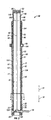
- Tensioner assembly 40 is directed to tensioner assembly 40 having cylinder 60, ram 80, stop tube 90, and air transfer tube 50.
- Tensioner assembly 40 includes a fully retracted position (FIGS. 1 and 2), a fully extended position (FIG. 3), and a plurality of partially extended positions defined therebetween.
- Cylinder 60 includes cylinder inner wall surface 61, cylinder outer wall surface 62, cylinder first end 63, and cylinder second end 64.
- Cylinder second end 64 includes attachment member 65 to facilitate securing cylinder second end 64, and thus, tensioner assembly 40, to a riser string, a drilling vessel, or other equipment or devices that are secured to the riser string.
- Attachment member 65 may be any device, e.g., bolts, flanges, etc., known to persons of ordinary skill in the art.
- Cylinder cavity 66 is disposed within cylinder 60 and defined by cylinder inner wall surface 61.
- Cylinder first end 63 includes opening 67 to permit ram 80 to move into and out of cylinder cavity 66 as discussed in greater detail below.
- Cylinder 60 also preferably includes annular manifold 68 to permit hydraulic fluid to be circulated around ram 80 and into hydraulic fluid accumulator 77 discussed in greater detail below.
- Ram 80 includes ram inner wall surface 81, ram outer wall surface 82, ram first end, or ram head, 83, and ram second end 84.
- Ram first end 83 includes attachment member 85 to facilitate securing ram first end 83, and thus, tensioner assembly 40, to a riser string, a drilling vessel, or other equipment or devices that are secured to the riser string.
- Attachment member 85 may be any device, e.g., bolts, flanges, etc., known to persons of ordinary skill in the art.
- Ram cavity 86 is disposed within ram 80 and defined by ram inner wall surface 81.
- Ram second end 84 includes ram opening 88 (FIG. 3) to permit hydraulic fluid to pass into and from ram cavity 86 as discussed in greater detail below.
- Stop tube 90 includes stop tube inner wall surface 91, stop tube outer wall surface 92, stop tube first end 93, stop tube second end 94, and stop tube cavity 96 disposed within stop tube 90 and defined by stop tube inner wall surface 91.
- ram 80 preferably, includes ram flange 89 (FIG. 1) disposed along a portion of ram outer wall surface 82, preferably near ram second end 84.
- Ram flange 89 contacts stop tube 90 when tensioner assembly 40 is in the fully extended position (FIG. 3).
- ram flange 80 facilitates maintaining ram 80 within cylinder cavity 66 and stop tube cavity 96.
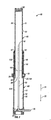
- Tensioner assembly 40 is assembled by inserting ram 80 into cylinder cavity 66 by placing ram second end 84 through cylinder opening 67 such that air transfer tube 50 is disposed within ram cavity 86.
- Ram 80 is inserted into cylinder cavity 66 until ram second end 84 contacts cylinder second end 64, i.e., tensioner assembly 40 is in the fully retracted position (FIGS. 1 and 2).
- Ram flange 89, or annular piston 20 are slidably engaged with cylinder inner wall surface 61, and hydraulic fluid accumulator 77 is formed between cylinder inner wall surface 61 and ram outer wall surface 82.
- Ram flange 89, or annular piston 20 is slidably engaged with cylinder inner wall surface 61 such that no hydraulic fluid or air is permitted to pass between ram flange 89, or annular piston 20, and cylinder inner wall surface 61.
- Stop tube 90 is then disposed around ram 80 (i.e., ram 80 is inserted into stop tube cavity 96) and stop tube 90 is inserted into cylinder cavity 66 such that stop tube outer wall surface 92 is in communication with cylinder inner wall surface 61 and stop tube inner wall surface 91 is slidably engaged with ram outer wall surface 82.
- Stop tube 90 is preferably secured to cylinder inner wall surface 61 such that stop tube is incapable of movement and no hydraulic fluid or air is permitted to pass between cylinder inner wall surface 61 and stop tube outer wall surface 92.
- stop tube 90 is secured in place by flange and bolt assembly 95.
- Stop tube inner wall surface 91 is slidably engaged with ram outer wall surface 82 such that no hydraulic fluid or air is permitted to pass between stop tube inner wall surface 91 and ram outer wall surface 82.
- ram flange 89 or annular piston 20 is permitted to slide along cylinder inner wall surface 61 until contacting stop tube 90.
- tensioner assembly 40 is in the fully extended position (FIG. 3).
- Air transfer tube 50 Disposed within cylinder cavity 66 and at least a portion of ram cavity 86 is gas, or air, transfer tube 50. While the tensioner assembly is discussed herein as having a "air,” it is to be understood that any gas may be used, e.g., atmospheric air or nitrogen. Air transfer tube 50 is in fluid communication with an air source (not shown), such as one or more air pressure vessels, that provides pressurized air into ram cavity 86 and cylinder cavity 66 to provide tensile force to tensioner assembly 40. Air transfer tube 50 includes air transfer tube opening 52. Preferably, cylinder second end 64 includes air passageway 54 to facilitate the transportation of air from the air source to air transfer tube 50.
- an air source such as one or more air pressure vessels
- hydraulic fluid accumulator 77 When tensioner assembly 40 is in the fullyretracted position (FIGS. 1 and 2), hydraulic fluid accumulator 77 is formed by ram outer wall surface 82 and cylinder inner wall surface 61 as an annular ring around ram 80. As tensioner assembly 40 is moved from the fully retracted position (FIGS. 1 and 2) to the fully extended position (FIG. 3), hydraulic fluid accumulator 77 and cylinder cavity 66 become in fluid communication with each other and the volume of the annular space forming hydraulic fluid accumulator 77 is reduced.
- tensioner assembly 40 includes a hydraulic fluid return line 70 in fluid communication with annular manifold 68 and cylinder cavity 66 and thus ram cavity 86.
- cylinder second end 64 includes hydraulic fluid passageway 74 to facilitate the transportation of hydraulic fluid from ram cavity 86 and cylinder cavity 66 to hydraulic fluid return line 70.
- Hydraulic fluid return line 70 preferably includes control valve 72 such as a Riser Inertia Management and Control® (RIMAC®) system to facilitate regulation of the flow of hydraulic fluid through hydraulic fluid return line 70 and to control the riser pipe in the event of an unexpected separation of ram 80 from cylinder 60.
- RIMAC® Riser Inertia Management and Control®
- the tensile force created by tensioner assembly 40 can be controlled such that the speed at which ram 80 moves within cylinder 70 and stop tube 90 does not exceed a set speed at which ram 80 may be forced from its slidable engagement with stop tube 90 or otherwise cause damage to tensioner assembly 40.
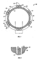
- annular piston 20 performs the function of ram flange 89. Like ram flange 89, annular piston 20 is disposed along ram outer wall surface 82 near ram second end 84. Unlike ram flange 89, however, which only provides the function of stopping further extension of ram 80, annular piston 20 controls the speed at which rain 80 moves within cylinder 70 and stop tube 90. As illustrated in FIGS. 4 and 5, annular piston 20 preferably includes a plurality of ports 22 through which hydraulic fluid is permitted to pass from hydraulic fluid accumulator 77 into cylinder cavity 66, and vice versa. Port 22 includes leaf spring 24 disposed over port 22 to facilitate controlling the flow of hydraulic fluid through port 22. Leaf spring 24 preferably includes at least one leaf spring orifice or opening 26 through which hydraulic fluid is permitted to pass.
- ports 22 are arranged in pairs with each pair of ports 22 having leaf spring 24 disposed above the pair of ports 22 with leaf spring orifice or opening 26 disposed above each port 22.
- Leaf spring 26 is curved upwardly, i.e., in the direction of first end 83, such that the flow of hydraulic fluid through port 22 in the direction of arrow 31 is buffered, or slowed, and such that the flow of hydraulic fluid through port 22 in the direction of arrow 32 is likewise buffered, or slowed.
- leaf spring 26 In situations in which ram 80 is being forced out of cylinder 60, i.e., in the direction of arrow 31 toward the fully extended position, at a high rate of speed, leaf spring 26 is flattened out to cover a portion of port 22, thereby restricting the flow of hydraulic fluid through port 22, and thus slowing the extension of ram 80 out of cylinder 60.
- Fastener devices e.g., bolts 28, may be used to secure leaf spring 26 to annular piston 20.
- annular piston 22 is described as having a plurality ofports 22, with a plurality of leaf springs 26, it is to be understood that annular piston 22 may only have one port, with, or without, a leaf spring 26, and leaf spring 26 may or may not be include leaf spring opening 26.
- cylinder cavity 66, ram cavity 86, and hydraulic fluid accumulator 77 may be filled with hydraulic fluid in the spaces represented by the reference numeral 104.
- Ram cavity 86 may then be partially filled with air in the space represented by the reference numeral 102 from a air source and passing through air transfer tube 50, thereby establishing a hydraulic fluid level 100 in a gas over hydraulic fluid arrangement. The pressures of the air and hydraulic fluid do not move ram 80 when the pressures are at equilibrium.
- the air in space 102 is pressurized by additional air being transported from the air source, through air passageway 54, through air transfer tube 50, out of air tube opening 52, and into space 102 of ram cavity 86. In so doing, the pressurized air in space 102 forces ram head 83 to move in the direction of arrow 31. Additionally, the pressurized air forces hydraulic fluid level 100 to be moved downward, in the direction of arrow 32.
- the pressurized hydraulic fluid in spaces 104 is compressed and facilitates exertion of an upward force, i.e., in the direction of arrow 31, to force ram head 83 to move in the direction of 31 until tensioner assembly reaches the fully extended position (FIG. 3), or until the pressure of the air and the pressure of the hydraulic fluid reach equilibrium.
- hydraulic fluid is transported from cylinder cavity 66, through annular piston 20 in the direction of arrow 31, by passing through ports 22, and into hydraulic fluid accumulator 77. In so doing, the volume of hydraulic fluid accumulator is increased.
- tensioner assembly 40 As air is transported from the air source into ram cavity 86, and thus ram 80 is moved in the direction of arrow 31, hydraulic fluid is transported from hydraulic fluid accumulator 77, through annular manifold 68, into hydraulic fluid return line 70, through hydraulic fluid return line 70, through control, valve 72, through hydraulic fluid passageway 74, and into cylinder cavity 66.
- hydraulic fluid level 100 is preferably always lower, i.e., closer to cylinder second end 64, than air transfer tube opening 52. Therefore, hydraulic fluid 104 will not be permitted to pass into air transfer tube 50.
- cylinder 60, ram 80, and stop tube 90 may be formed out of any material known to persons of ordinary skill in the art, preferably, cylinder 60, ram 80, and stop tube 90 are manufactured from a light weight material that helps to reduce the overall weight of tensioner assembly 40, helps to eliminate friction and metal contact within cylinder 60 and stop tube 90, and helps reduce the potential for electrolysis and galvanic action causing corrosion. Examples include, but are not limited to, carbon steel, stainless steel, aluminum and titanium.
- Tensioner assembly 40 may be connected directly to the riser string or indirectly to the riser string by connecting tensioner assembly 40 to a riser ring or other device which facilitates connecting tensioner assembly 40 to the riser string.
- Tensioner assembly 40 of the present invention may be utilized to compensate for offset of an oil drilling vessel connected to a riser or blowout preventer stack.
- the tensioner assembly is placed, or disposed, in communication with an oil drilling vessel and the riser or blowout preventer stack rising through the ocean from the wellbore.
- the oil drilling vessel may be stabilized using the tensioner assembly of the present invention by maintaining and adjusting tension in the cylinder by maintaining and adjusting the pressure in the cylinder and the ram by placing the ram or air transfer tube and air source in communication with at least one control source.
- the annular piston may include only one port. Further, each port in the annular piston does not require a leaf spring, thereby permitting each port in the annular piston to be modified to restrict the flow of hydraulic fluid.
- the tensioner assembly may be assembled using bolts, welding, or any other device or method known to persons of ordinary skill in the art.
- the stop tube may be a flange or ledge formed integral with the cylinder inner wall surface and disposed within the cylinder cavity.
- the individual components may be manufactured out of any material and through any method known to persons of ordinary skill in the art. Accordingly, the invention is therefore to be limited only by the scope of the claims.
Landscapes
- Engineering & Computer Science (AREA)
- Geology (AREA)
- Life Sciences & Earth Sciences (AREA)
- Mining & Mineral Resources (AREA)
- Physics & Mathematics (AREA)
- Environmental & Geological Engineering (AREA)
- Fluid Mechanics (AREA)
- Mechanical Engineering (AREA)
- General Life Sciences & Earth Sciences (AREA)
- Geochemistry & Mineralogy (AREA)
- Supply Devices, Intensifiers, Converters, And Telemotors (AREA)
- Other Liquid Machine Or Engine Such As Wave Power Use (AREA)
- Control Of Transmission Device (AREA)
- Filling Or Discharging Of Gas Storage Vessels (AREA)
Claims (23)
- Spannvorrichtung (40), welche eine vollständig ausgefahrene Stellung, eine vollständig zurückgezogene Stellung sowie eine Vielzahl an teilweise ausgefahrenen Stellungen, die dazwischenliegen, einnehmen kann, enthaltend:einen Zylinder (60) mit einem ersten Zylinderende (63), einem zweiten Zylinderende (64), einer Zyfinderaußenwandfläche (62), einer Zylinderinnenwandfläche (61) und einem Zylinderhohlraum (66),wobei das erste Zylinderende (63) eine Zylinderöffnung (67), das zweite Zylinderende (64) ein erstes Montageelement (65) und der Zylinderhohlraum (66) ein erstes darin angeordnetes Volumen eines Hydraulikfluids aufweist;
ein Anschlagrohr (90) mit einem ersten Anschlagrohrende (93), einem zweiten Anschlagrohrende (94), einer Anschlagrohraußenwandfläche (92), einer Anschlagrohrinnenwandfläche (91) und einem Anschlagrohrhohlraum (96), wobei das Anschlagrohr (90) entlang zumindest eines Abschnitts der Zylinderinnenwandfläche (61) in der Weise angeordnet ist, dass die Zylinderwandinnenfläche (61) in Verbindung mit der Anschlagrohraußenwandfläche (92) steht;
einen Stempel (80) mit einem ersten Stempelende (83), einem zweiten Stempelende (84), einer Stempelinnenwandfläche (81), einer Stempelwandaußenwandfläche (82) und einem Stempelhohlraum (86), wobei das erste Stempelende (83) abgedichtet ist und ein zweites Montageelement (85) enthält, wobei das zweite Stempelende (84) einen Stempelflansch (89), der entlang der Stempelwandaußenfläche (82) angeordnet ist, und eine Stempelöffnung (88) für eine Fluidverbindung zwischen dem Stempelhohlraum (86) und dem Zylinderhohlraum (66) besitzt, wobei Zylinderhohlraum (66) besitzt, wobei der Stempelhohlraum (66) ein zweites Volumen des Hydraulikfluids und ein Gas, das darin in der Weise angeordnet ist, dass es sich oberhalb des Hydraulikfluids befindet, aufweist, wobei die Stempelaußenwandfläche (82) in verschiebbarem Eingriff mit einem Abschnitt der Anschlagrohrinnenwandfläche (91) und der Stempelflansch (89) in verschiebbarem Eingriff mit einem Abschnitt der Zylinderinnenwandfläche (61) stehen;
eine Hydraulikfluidsammeleinrichtung (77), die als ein ringförmiger Raum ausgebildet ist, der durch die Zylinderinnenwandfläche (61), die Stempelwandaußenfläche (82), das zweite Anschlagrohrende (94) und den Stempelflansch (89) gebildet ist;
zumindest eine Hydraulikfluidrückführleitung (70), die in Fluidverbindung mit der Hydraulikfluidsammeleinrichtung (77) und dem Zylinderhohlraum (66) steht; und
zumindest ein Gasförderrohr (50), das innerhalb eines Abschnitts des Zylinderhohlraums (66) und innerhalb eines Abschnitts des Stempelhohlraums (86) angeordnet ist, wobei das zumindest eine Gasförderrohr (50) in Fluidverbindung mit einer Gasquelle und dem Gas, welches sich innerhalb des Stempelhohlraums (86) befindet, steht. - Spannvorrichtung nach Anspruch 1,
wobei das zweite Zylinderende (64) einen Gaskanal (54) aufweist, der in Fluidverbindung mit dem zumindest einen Gasförderrohr (50) und der Gasquelle steht. - Spannvorrichtung nach Anspruch 2,
wobei das zweite Zylinderende (64) einen Hydraulikfluidkanal (74) aufweist, der in Fluidverbindung mit dem Zylinderhohlraum (66) und der Hydraulikfluidrückführleitung (70) steht. - Spannvorrichtung nach Anspruch 3,
wobei die Hydraulikfluidrückführleitung (70) einen ringförmigen Verteiler (68) besitzt, der entlang eines Abschnitt der Zylinderaußenwand (62) angeordnet ist und der in Fluidverbindung mit der Hydraulikfluidsammeleinrichtung (77) und mit der zumindest einen Hydraulikfluidrückführleitung (70) steht. - Spannvorrichtung nach Anspruch 1,
wobei das zweite Zylinderende (64) einen Hydraulikfluidkanal (74) besitzt, der in Fluidverbindung mit dem Zylinderhohlraum (66) und der Hydraulikfluidrückführleitung (70) steht. - Spannvorrichtung nach Anspruch 5,
wobei die Hydraulikfluidrückführleitung (70) einen ringförmigen Verteiler (68) aufweist, der entlang eines Abschnitts der Zylinderaußenwand (62) angeordnet ist und der in Fluidverbindung mit der Hydraulikfluidsammeleinrichtung (77) und der zumindest einen Hydraulikfluidrückführleitung (70) steht. - Spannvorrichtung (40), die eine vollständig ausgefahrene Stellung, eine vollständig zurückgezogene Stellung und eine Vielzahl an teilweise ausgefahrenen Stellungen, die sich zwischen der vollständig ausgefahrenen Stellung und der vollständig zurückgezogenen Stellung befinden, aufweist, enthaltend:einen Zylinder (60) mit einem ersten Zylinderende (63), einem zweiten Zylinderende (64), einer Zylinderaußenwandfläche (62), einer Zylinderinnenwandfläche (61) und einem Zylinderhohlraum (66),wobei das erste Zylinderende (63) eine Zylinderöffnung (67), das zweite Zylinderende (64) ein erstes Montageelement (65) und der Zylinderhohlraum (66) ein erstes darin angeordnetes Volumen eines Hydraulikfluids aufweist;
ein Anschlagrohr (90) mit einem ersten Anschlagrohrende (93), einem zweiten Anschlagrohrende (94), einer Anschlagrohraußenwandfläche (92), einer Anschlagrohrinnenwandfläche (91) und einem Anschlagrohrhohlraum (96), wobei das Anschlagrohr (90) entlang zumindest eines Abschnitts der Zylinderinnenwandfläche (64) in der Weise angeordnet ist, dass die Zylinderwandinnenfläche (64) in Verbindung mit der Anschlagrohraußenwandfläche (92) steht;
einen Stempel (80) mit einem ersten Stempelende (83), einem zweiten Stempelende (84), einer Stempelinnenwandfläche (81), einer Stempelwandaußenwandfläche (82) und einem Stempelhohlraum (86), wobei das erste Stempelende (83) abgedichtet ist und ein zweites Montageelement (85) enthält, wobei das zweite Stempelende (84) einen ringförmigen Kolben (20), der entlang der Stempelwandaußenfläche (82) angeordnet ist und eine Stempelöffnung (88) für eine Fluidverbindung zwischen dem Stempelhohlraum (86) und dem Zylinderhohlraum (66) besitzt, wobei der ringförmige Kolben (20) mindestens eine Öffnung (22) hat, wobei der Stempelhohlraum (86) ein zweites Volumen des Hydraulikfluids und ein Gas, das darin in der Weise angeordnet ist, dass es sich oberhalb des Hydraulikfluids befindet, aufweist, wobei die Stempelwandaußenfläche (82) in verschiebbarem Eingriff mit einem Abschnitt der Anschlagrohrinnenwandfläche (91) und der ringförmige Kolben (20) in verschiebbarem Eingriff mit einem Abschnitt der Zylinderwandinnenfläche (61) stehen;
eine Hydraulikfluidsammeleinrichtung (77), die als ein ringförmiger Raum ausgebildet ist, der durch die Zylinderwandinnenfläche (61), der Stempelwandaußenfläche (82), das zweite Anschlagrohrende (94) und den ringförmigen Kolben (20) gebildet wird, wobei die Hydraulikfluidsammeleinrichtung (77) über die zumindest eine Öffnung (22) an dem Ringkolben (20) in Fluidverbindung mit dem Zylinderhohlraum (66) steht; und
zumindest ein Gasförderrohr (50), das innerhalb eines Abschnitts des Zylinderhohlraums (66) und innerhalb eines Abschnitts des Stempelhohlraums (86) angeordnet ist, wobei das zumindest eine Gasförderrohr (50) in Fluidverbindung mit einer Gasquelle und dem Gas, welches sich innerhalb des Stempelhohlraums (86) befindet, steht. - Spannvorrichtung nach Anspruch 7,
wobei zumindest eine der wenigstens einen Öffnung (22) des Ringkolbens (20) mindestens eine Blattfeder (24) enthält, die über der zumindest einen der wenigstens einen Öffnung (22) angeordnet ist. - Spannvorrichtung nach Anspruch 8,
wobei zumindest eine der wenigstens einen Blattfeder (24) in Richtung des ersten Stempelendes (83) nach oben gekrümmt ist. - Spannvorrichtung nach Anspruch 9,
wobei die zumindest eine der wenigstens einen Blattfeder (24) zumindest eine Blattfederöffnung (26) aufweist. - Spannvorrichtung nach Anspruch 10,
wobei das zweite Zylinderende (64) einen Gaskanal (54) besitzt, der in Fluidverbindung mit dem zumindest einen Gasförderrohr (50) und der Gasquelle steht. - Spannvorrichtung nach Anspruch 11,
wobei die Hydraulikfluidsammeleinrichtung (77) einen ringförmigen Verteiler aufweist, der entlang eines Abschnitts der Zylinderaußenwand (62) angeordnet ist und in Fluidverbindung mit der Hydraulikfluidsammeleinrichtung (77) steht. - Spannvorrichtung nach Anspruch 7,
wobei der Ringkolben (20) zumindest ein Paar Öffnungen (22) aufweist. - Spannvorrichtung nach Anspruch 13,
wobei zumindest eines des wenigstens einen Öffnungspaares (22) zumindest eine Blattfeder (24) aufweist, die über dem zumindest einen des wenigstens einen Paares Öffnungen (22) angeordnet ist. - Spannvorrichtung nach Anspruch 14,
wobei zumindest eine der wenigstens einen Blattfeder (24) in Richtung des ersten Stempelendes (83) nach oben gekrümmt ist. - Spannvorrichtung nach Anspruch 15,
wobei zumindest eine der wenigstens einen Blattfeder (24) zumindest eine Blattfederöffnung (26) enthält. - Spannvorrichtung nach Anspruch 16,
wobei das zweite Zylinderende (64) einen Gaskanal (54) besitzt, der in Fluidverbindung mit dem zumindest einen Gasförderrohr (50) und der Gasquelle steht. - Spannvorrichtung nach Anspruch 17,
wobei die Hydraulikfluidsammeleinrichtung (77) einen Ringverteiler (68) aufweist, der entlang eines Abschnitt der Zylinderaußenwand (62) angeordnet ist und in Fluidverbindung mit der Hydraulikfluidsammeleinrichtung (77) steht. - Spannvorrichtung nach Anspruch 13,
wobei jedes des zumindest einen Paares Öffnungen (22) eine Blattfeder (24) aufweist, die oberhalb jedes des zumindest einen Paares Öffnungen (22) angeordnet ist. - Spannvorrichtung nach Anspruch 19,
wobei jede der Blattfedern (24) oberhalb jedes des wenigstens einen Paares Öffnungen (22) in Richtung des ersten Stempelendes (83) nach oben gekrümmt ist. - Spannvorrichtung nach Anspruch 20,
wobei jede der Blattfedern (24) zumindest eine Blattfederöffnung (26) aufweist, die oberhalb jeder der Öffnungen (22) angeordnet ist. - Spannvorrichtung nach Anspruch 21,
wobei das zweite Zylinderende (64) einen Gaskanal (54) aufweist, der in Fluidverbindung mit dem zumindest einen Gasförderrohr (50) und der Gasquelle steht. - Spannvorrichtung nach Anspruch 22,
wobei die Hydraulikfluidsammeleinrichtung (77) einen ringförmigen Verteiler (68) aufweist, der entlang eines Abschnitts der Zylinderaußenwand (62) angeordnet ist und in Fluidverbindung mit der Hydraulikfluidsammeleinrichtung (77) steht.
Applications Claiming Priority (2)
| Application Number | Priority Date | Filing Date | Title |
|---|---|---|---|
| US314710 | 2002-12-09 | ||
| US10/314,710 US7008340B2 (en) | 2002-12-09 | 2002-12-09 | Ram-type tensioner assembly having integral hydraulic fluid accumulator |
Publications (2)
| Publication Number | Publication Date |
|---|---|
| EP1428971A1 EP1428971A1 (de) | 2004-06-16 |
| EP1428971B1 true EP1428971B1 (de) | 2006-05-03 |
Family
ID=30443941
Family Applications (1)
| Application Number | Title | Priority Date | Filing Date |
|---|---|---|---|
| EP03257691A Expired - Lifetime EP1428971B1 (de) | 2002-12-09 | 2003-12-08 | Spannanordnungsvorrichtung mit integriertem Druckmittelspeicher |
Country Status (7)
| Country | Link |
|---|---|
| US (2) | US7008340B2 (de) |
| EP (1) | EP1428971B1 (de) |
| AT (1) | ATE325256T1 (de) |
| BR (1) | BR0306552B1 (de) |
| DE (1) | DE60304976D1 (de) |
| NO (1) | NO324759B1 (de) |
| SG (1) | SG125097A1 (de) |
Families Citing this family (21)
| Publication number | Priority date | Publication date | Assignee | Title |
|---|---|---|---|---|
| DE4119015A1 (de) * | 1991-06-08 | 1992-12-10 | Kabelmetal Electro Gmbh | Daempfungsglied zum einbau in optische uebertragungssysteme |
| US7231981B2 (en) * | 2003-10-08 | 2007-06-19 | National Oilwell, L.P. | Inline compensator for a floating drill rig |
| US20050074296A1 (en) * | 2003-10-15 | 2005-04-07 | Mccarty Jeffery Kirk | Hydro-pneumatic tensioner with stiffness altering secondary accumulator |
| US7819195B2 (en) * | 2005-11-16 | 2010-10-26 | Vetco Gray Inc. | External high pressure fluid reservoir for riser tensioner cylinder assembly |
| EP2054335B1 (de) * | 2006-08-15 | 2012-04-04 | Hydralift Amclyde, Inc. | Direkt wirkender einzelscheiben-aktiv/passiv-hubkompensator |
| US20080187401A1 (en) * | 2007-02-02 | 2008-08-07 | Tom Bishop | Riser tensioner for an offshore platform |
| US7329070B1 (en) | 2007-03-30 | 2008-02-12 | Atp Oil & Gas Corporation | Ram-type tensioner assembly with accumulators |
| US7270071B1 (en) | 2007-03-30 | 2007-09-18 | Atp Oil & Gas Corporation | Deep draft semisubmersible movable offshore structure |
| US8733447B2 (en) * | 2008-04-10 | 2014-05-27 | Weatherford/Lamb, Inc. | Landing string compensator |
| NO330288B1 (no) * | 2008-06-20 | 2011-03-21 | Norocean As | Slippforbindelse med justerbar forspenning |
| DE102010032415A1 (de) * | 2010-07-27 | 2012-02-02 | Hydac Technology Gmbh | Vorrichtung zur Rückgewinnung von Energie |
| US8157013B1 (en) * | 2010-12-08 | 2012-04-17 | Drilling Technological Innovations, LLC | Tensioner system with recoil controls |
| US8517110B2 (en) | 2011-05-17 | 2013-08-27 | Drilling Technology Innovations, LLC | Ram tensioner system |
| EP2797830B1 (de) | 2011-12-30 | 2016-03-09 | National Oilwell Varco, L.P. | Tiefwasser-gelenkauslegerkran |
| WO2013154566A1 (en) * | 2012-04-12 | 2013-10-17 | Eaton Corporation | Plunger-type wire riser tensioner |
| BR112015013690B1 (pt) | 2012-12-13 | 2021-11-16 | National Oilwell Varco, L.P. | Sistema de compensação de balouço remoto e guindaste tendo um sistema de compensação de balouço |
| NO339752B1 (no) * | 2014-02-27 | 2017-01-30 | Mhwirth As | Kompakt kompenseringsenhet |
| BR102015029061B1 (pt) * | 2014-11-21 | 2022-03-29 | Dril-Quip, Inc | Sistema de elemento de tensionamento de riser estilo êmbolo melhorado e método |
| BR102015029094B1 (pt) | 2014-11-21 | 2022-03-22 | Dril-Quip, Inc. | Conjunto de cilindro para uso em um tensor de riser e método para operar um cilindro tensor de riser |
| US10174566B2 (en) | 2016-03-02 | 2019-01-08 | Vetco Gray, LLC | Inverted pull-up riser tensioner |
| US9816538B1 (en) | 2016-08-31 | 2017-11-14 | Vetco Gray Inc. | Tensioner cylinder with internal gas bladder in high pressure chamber |
Family Cites Families (70)
| Publication number | Priority date | Publication date | Assignee | Title |
|---|---|---|---|---|
| US913970A (en) | 1902-08-09 | 1909-03-02 | Pittsburg Pneumatic Company | Fluid-pressure ram. |
| US1815907A (en) * | 1928-03-24 | 1931-07-28 | Wayne Co | Elevator |
| US3280908A (en) | 1962-05-21 | 1966-10-25 | Fmc Corp | Apparatus for underwater drilling and well completion |
| US3208728A (en) | 1962-11-19 | 1965-09-28 | Exxon Production Research Co | Apparatus for use on floating drilling platforms |
| US3313345A (en) | 1964-06-02 | 1967-04-11 | Chevron Res | Method and apparatus for offshore drilling and well completion |
| US3643751A (en) | 1969-12-15 | 1972-02-22 | Charles D Crickmer | Hydrostatic riser pipe tensioner |
| US3718316A (en) | 1970-09-04 | 1973-02-27 | Vetco Offshore Ind Inc | Hydraulic-pneumatic weight control and compensating apparatus |
| US3680644A (en) | 1970-12-28 | 1972-08-01 | Santa Fe Int Corp | Pile driving system and apparatus |
| US3793835A (en) | 1972-02-02 | 1974-02-26 | Vetco Offshore Ind Inc | Variable rate hydraulic-pneumatic weight control and compensating apparatus |
| US3804183A (en) | 1972-05-01 | 1974-04-16 | Rucker Co | Drill string compensator |
| US3841607A (en) | 1972-07-25 | 1974-10-15 | Vetco Offshore Ind Inc | Hydraulic motion compensating apparatus |
| US3897045A (en) | 1973-09-12 | 1975-07-29 | Vetco Offshore Ind Inc | Riser pipe and guide line tensioning apparatus |
| US3912227A (en) * | 1973-10-17 | 1975-10-14 | Drilling Syst Int | Motion compensation and/or weight control system |
| US3955621A (en) | 1975-02-14 | 1976-05-11 | Houston Engineers, Inc. | Riser assembly |
| US4004532A (en) | 1975-05-05 | 1977-01-25 | Western Gear Corporation | Riser tension system for floating platform |
| US4068868A (en) | 1975-09-02 | 1978-01-17 | Vetco Offshore Industries, Inc. | Flexible joints for marine risers |
| US4075858A (en) | 1976-05-17 | 1978-02-28 | Frederick Leonard L | Hydraulic pile driving apparatus and method |
| GB1600740A (en) | 1977-04-23 | 1981-10-21 | Brown Bros & Co Ltd | Tensioner device for offshore oil production and exploration platfroms |
| US4222341A (en) | 1978-01-11 | 1980-09-16 | Western Gear Corporation | Riser tensioning wave and tide compensating system for a floating platform |
| US4176722A (en) | 1978-03-15 | 1979-12-04 | Global Marine, Inc. | Marine riser system with dual purpose lift and heave compensator mechanism |
| US4351261A (en) | 1978-05-01 | 1982-09-28 | Sedco, Inc. | Riser recoil preventer system |
| US4272059A (en) | 1978-06-16 | 1981-06-09 | Exxon Production Research Company | Riser tensioner system |
| US4317586A (en) | 1979-01-25 | 1982-03-02 | Campbell Joseph K | Pipe stress/strain neutralizer |
| FR2484352B1 (fr) * | 1980-06-12 | 1986-01-31 | Cneema | Dispositif de tension automatique pour chenilles |
| US4379657A (en) | 1980-06-19 | 1983-04-12 | Conoco Inc. | Riser tensioner |
| US4362438A (en) | 1980-10-03 | 1982-12-07 | A/S Akers Mek. Verksted | Supporting device |
| DE3047375C2 (de) | 1980-12-16 | 1985-09-05 | Koehring Gmbh, 2000 Hamburg | Tauchfähige Rammvorrichtung |
| US4449854A (en) | 1981-02-12 | 1984-05-22 | Nl Industries, Inc. | Motion compensator system |
| US4367981A (en) | 1981-06-29 | 1983-01-11 | Combustion Engineering, Inc. | Fluid pressure-tensioned slip joint for drilling riser |
| US4432420A (en) | 1981-08-06 | 1984-02-21 | Exxon Production Research Co. | Riser tensioner safety system |
| US4423983A (en) | 1981-08-14 | 1984-01-03 | Sedco-Hamilton Production Services | Marine riser system |
| US4421173A (en) | 1981-08-20 | 1983-12-20 | Nl Industries, Inc. | Motion compensator with improved position indicator |
| JPS59177494A (ja) | 1983-03-29 | 1984-10-08 | 工業技術院長 | ライザ用テレスコピツクジヨイント |
| US4501219A (en) | 1983-04-04 | 1985-02-26 | Nl Industries, Inc. | Tensioner apparatus with emergency limit means |
| US4473323A (en) | 1983-04-14 | 1984-09-25 | Exxon Production Research Co. | Buoyant arm for maintaining tension on a drilling riser |
| NO842405L (no) | 1983-06-17 | 1985-03-27 | Novacorp Int Consulting Ltd | Anordning og fremgangsmaate for fortoeyning av et hydrokarbon-produksjonssystem tilknyttet et skip |
| US4638978A (en) | 1983-07-22 | 1987-01-27 | Jordan Larry B | Hydropneumatic cable tensioner |
| US4712620A (en) | 1985-01-31 | 1987-12-15 | Vetco Gray Inc. | Upper marine riser package |
| US4799827A (en) | 1986-11-17 | 1989-01-24 | Vetco Gray Inc. | Modular riser tensioner incorporating integral hydraulic cylinder accumulator units |
| US4787778A (en) | 1986-12-01 | 1988-11-29 | Conoco Inc. | Method and apparatus for tensioning a riser |
| CA1259232A (en) | 1986-12-24 | 1989-09-12 | Nikolai P. Ermilov | Percussive tool |
| US4883387A (en) | 1987-04-24 | 1989-11-28 | Conoco, Inc. | Apparatus for tensioning a riser |
| US4808035A (en) | 1987-05-13 | 1989-02-28 | Exxon Production Research Company | Pneumatic riser tensioner |
| DE3719163C1 (de) * | 1987-06-09 | 1988-07-14 | Porsche Ag | Kettenspanner |
| US4886397A (en) | 1987-08-27 | 1989-12-12 | Cherbonnier T Dave | Dynamic load compensating system |
| DE4023728A1 (de) * | 1990-07-26 | 1992-01-30 | Porsche Ag | Kettenspanner fuer eine brennkraftmaschine |
| SK279150B6 (sk) | 1990-11-09 | 1998-07-08 | Permon | Pneumatické ponorné vŕtacie náradie |
| GB2250763B (en) | 1990-12-13 | 1995-08-02 | Ltv Energy Prod Co | Riser tensioner system for use on offshore platforms using elastomeric pads or helical metal compression springs |
| US5101905A (en) | 1991-02-26 | 1992-04-07 | Ltv Energy Products Company | Riser tensioner system for use on offshore platforms |
| US5169265A (en) | 1991-09-27 | 1992-12-08 | Paul-Munroe Hydraulics, Inc. | Passive fire protection system for marine risers |
| US5209302A (en) | 1991-10-04 | 1993-05-11 | Retsco, Inc. | Semi-active heave compensation system for marine vessels |
| US5252004A (en) | 1992-07-13 | 1993-10-12 | Paul-Munroe Engineering | Rod accumulator riser tensioning cylinder assembly |
| DE4419499A1 (de) | 1994-06-03 | 1995-12-07 | Interoc Vertriebsgesellschaft | Hydraulisches Schlaggerät mit stufenlos regelbarer Schlagzahl und Schlagenergie |
| US5551803A (en) | 1994-10-05 | 1996-09-03 | Abb Vetco Gray, Inc. | Riser tensioning mechanism for floating platforms |
| NO302493B1 (no) | 1996-05-13 | 1998-03-09 | Maritime Hydraulics As | Glideskjöt |
| US5727630A (en) | 1996-08-09 | 1998-03-17 | Abb Vetco Gray Inc. | Telescopic joint control line system |
| DE19652079C2 (de) | 1996-12-14 | 1999-02-25 | Krupp Berco Bautechnik Gmbh | Fluidbetriebenes Schlagwerk |
| US5758990A (en) | 1997-02-21 | 1998-06-02 | Deep Oil Technology, Incorporated | Riser tensioning device |
| US5846028A (en) | 1997-08-01 | 1998-12-08 | Hydralift, Inc. | Controlled pressure multi-cylinder riser tensioner and method |
| US5951061A (en) | 1997-08-13 | 1999-09-14 | Continental Emsco Company | Elastomeric subsea flex joint and swivel for offshore risers |
| NL1007798C2 (nl) | 1997-12-15 | 1999-06-23 | Huisman Spec Lifting Equip Bv | Riser-tensioner. |
| FI105594B (fi) | 1998-02-05 | 2000-09-15 | Tamrock Oy | Sovitelma hydraulisen rikotuslaitteen huollon tarpeen tunnistamiseksi |
| FI107891B (fi) | 1998-03-30 | 2001-10-31 | Sandvik Tamrock Oy | Painenestekäyttöinen iskulaite |
| US6068066A (en) | 1998-08-20 | 2000-05-30 | Byrt; Harry F. | Hydraulic drilling rig |
| US6173781B1 (en) | 1998-10-28 | 2001-01-16 | Deep Vision Llc | Slip joint intervention riser with pressure seals and method of using the same |
| US6691784B1 (en) * | 1999-08-31 | 2004-02-17 | Kvaerner Oil & Gas A.S. | Riser tensioning system |
| US6419277B1 (en) | 1999-10-29 | 2002-07-16 | Hydril Company | Conduit section having threaded section connectors and external conduits attached thereto |
| US6343893B1 (en) | 1999-11-29 | 2002-02-05 | Mercur Slimhole Drilling And Intervention As | Arrangement for controlling floating drilling and intervention vessels |
| US6431284B1 (en) | 2000-10-03 | 2002-08-13 | Cso Aker Maritime, Inc. | Gimbaled table riser support system |
| FI112450B (fi) | 2000-10-09 | 2003-12-15 | Sandvik Tamrock Oy | Rikotuslaite ja työkalu |
-
2002
- 2002-12-09 US US10/314,710 patent/US7008340B2/en not_active Expired - Lifetime
-
2003
- 2003-11-19 SG SG200306913A patent/SG125097A1/en unknown
- 2003-11-28 NO NO20035285A patent/NO324759B1/no not_active IP Right Cessation
- 2003-12-04 BR BRPI0306552-9A patent/BR0306552B1/pt active IP Right Grant
- 2003-12-08 DE DE60304976T patent/DE60304976D1/de not_active Expired - Lifetime
- 2003-12-08 EP EP03257691A patent/EP1428971B1/de not_active Expired - Lifetime
- 2003-12-08 AT AT03257691T patent/ATE325256T1/de not_active IP Right Cessation
-
2006
- 2006-03-03 US US11/368,076 patent/US7131922B2/en not_active Expired - Lifetime
Also Published As
| Publication number | Publication date |
|---|---|
| EP1428971A1 (de) | 2004-06-16 |
| NO20035285D0 (no) | 2003-11-28 |
| ATE325256T1 (de) | 2006-06-15 |
| US20040110589A1 (en) | 2004-06-10 |
| DE60304976D1 (de) | 2006-06-08 |
| US7008340B2 (en) | 2006-03-07 |
| BR0306552B1 (pt) | 2015-01-13 |
| US7131922B2 (en) | 2006-11-07 |
| NO324759B1 (no) | 2007-12-10 |
| NO20035285L (no) | 2004-06-10 |
| BR0306552A (pt) | 2004-10-05 |
| US20060154764A1 (en) | 2006-07-13 |
| SG125097A1 (en) | 2006-09-29 |
Similar Documents
| Publication | Publication Date | Title |
|---|---|---|
| EP1428971B1 (de) | Spannanordnungsvorrichtung mit integriertem Druckmittelspeicher | |
| US4432420A (en) | Riser tensioner safety system | |
| US6530430B2 (en) | Tensioner/slip-joint assembly | |
| EP1428973B1 (de) | Tragbarer Tauschwingungskompensator | |
| AU773461B2 (en) | Riser tensioning system | |
| US7112011B2 (en) | Hydro-pneumatic tensioner with stiffness altering secondary accumulator | |
| EP1316671B1 (de) | Kolineare Spannvorrichtung und Verfahren zur Montage von Bohrloch- und Produktionssteigrohren unter Verwendung desselben | |
| CN105283380B (zh) | 用于干树半潜结构的立管张紧装置导体 | |
| US20110147002A1 (en) | Subsea Differential-Area Accumulator | |
| AU2015100331A4 (en) | Heave compensation and tensioning apparatus, and method of use thereof | |
| US20190071938A1 (en) | System and method for providing tension or heave compensation in an offshore drilling environment | |
| US11448017B2 (en) | Compensated elevator link | |
| AU2017222210A1 (en) | Stress reducing system and associated method | |
| NO20190699A1 (en) | Riser support system | |
| GB2515391A (en) | Heave compensation and tensioning apparatus, and method of use thereof | |
| NZ747890A (en) | Compensated Elevator Link |
Legal Events
| Date | Code | Title | Description |
|---|---|---|---|
| PUAI | Public reference made under article 153(3) epc to a published international application that has entered the european phase |
Free format text: ORIGINAL CODE: 0009012 |
|
| AK | Designated contracting states |
Kind code of ref document: A1 Designated state(s): AT BE BG CH CY CZ DE DK EE ES FI FR GB GR HU IE IT LI LU MC NL PT RO SE SI SK TR |
|
| AX | Request for extension of the european patent |
Extension state: AL LT LV MK |
|
| 17P | Request for examination filed |
Effective date: 20041208 |
|
| AKX | Designation fees paid |
Designated state(s): AT BE BG CH CY CZ DE DK EE ES FI FR GB GR HU IE IT LI LU MC NL PT RO SE SI SK TR |
|
| AXX | Extension fees paid |
Extension state: MK Payment date: 20041208 Extension state: AL Payment date: 20041208 Extension state: LV Payment date: 20041208 Extension state: LT Payment date: 20041208 |
|
| GRAP | Despatch of communication of intention to grant a patent |
Free format text: ORIGINAL CODE: EPIDOSNIGR1 |
|
| GRAC | Information related to communication of intention to grant a patent modified |
Free format text: ORIGINAL CODE: EPIDOSCIGR1 |
|
| GRAS | Grant fee paid |
Free format text: ORIGINAL CODE: EPIDOSNIGR3 |
|
| GRAA | (expected) grant |
Free format text: ORIGINAL CODE: 0009210 |
|
| AK | Designated contracting states |
Kind code of ref document: B1 Designated state(s): AT BE BG CH CY CZ DE DK EE ES FI FR GB GR HU IE IT LI LU MC NL PT RO SE SI SK TR |
|
| AX | Request for extension of the european patent |
Extension state: AL LT LV MK |
|
| PG25 | Lapsed in a contracting state [announced via postgrant information from national office to epo] |
Ref country code: SK Free format text: LAPSE BECAUSE OF FAILURE TO SUBMIT A TRANSLATION OF THE DESCRIPTION OR TO PAY THE FEE WITHIN THE PRESCRIBED TIME-LIMIT Effective date: 20060503 Ref country code: BE Free format text: LAPSE BECAUSE OF FAILURE TO SUBMIT A TRANSLATION OF THE DESCRIPTION OR TO PAY THE FEE WITHIN THE PRESCRIBED TIME-LIMIT Effective date: 20060503 Ref country code: NL Free format text: LAPSE BECAUSE OF FAILURE TO SUBMIT A TRANSLATION OF THE DESCRIPTION OR TO PAY THE FEE WITHIN THE PRESCRIBED TIME-LIMIT Effective date: 20060503 Ref country code: IT Free format text: LAPSE BECAUSE OF FAILURE TO SUBMIT A TRANSLATION OF THE DESCRIPTION OR TO PAY THE FEE WITHIN THE PRESCRIBED TIME-LIMIT;WARNING: LAPSES OF ITALIAN PATENTS WITH EFFECTIVE DATE BEFORE 2007 MAY HAVE OCCURRED AT ANY TIME BEFORE 2007. THE CORRECT EFFECTIVE DATE MAY BE DIFFERENT FROM THE ONE RECORDED. Effective date: 20060503 Ref country code: LI Free format text: LAPSE BECAUSE OF FAILURE TO SUBMIT A TRANSLATION OF THE DESCRIPTION OR TO PAY THE FEE WITHIN THE PRESCRIBED TIME-LIMIT Effective date: 20060503 Ref country code: FI Free format text: LAPSE BECAUSE OF FAILURE TO SUBMIT A TRANSLATION OF THE DESCRIPTION OR TO PAY THE FEE WITHIN THE PRESCRIBED TIME-LIMIT Effective date: 20060503 Ref country code: AT Free format text: LAPSE BECAUSE OF FAILURE TO SUBMIT A TRANSLATION OF THE DESCRIPTION OR TO PAY THE FEE WITHIN THE PRESCRIBED TIME-LIMIT Effective date: 20060503 Ref country code: SI Free format text: LAPSE BECAUSE OF FAILURE TO SUBMIT A TRANSLATION OF THE DESCRIPTION OR TO PAY THE FEE WITHIN THE PRESCRIBED TIME-LIMIT Effective date: 20060503 Ref country code: CH Free format text: LAPSE BECAUSE OF FAILURE TO SUBMIT A TRANSLATION OF THE DESCRIPTION OR TO PAY THE FEE WITHIN THE PRESCRIBED TIME-LIMIT Effective date: 20060503 Ref country code: RO Free format text: LAPSE BECAUSE OF FAILURE TO SUBMIT A TRANSLATION OF THE DESCRIPTION OR TO PAY THE FEE WITHIN THE PRESCRIBED TIME-LIMIT Effective date: 20060503 Ref country code: CZ Free format text: LAPSE BECAUSE OF FAILURE TO SUBMIT A TRANSLATION OF THE DESCRIPTION OR TO PAY THE FEE WITHIN THE PRESCRIBED TIME-LIMIT Effective date: 20060503 |
|
| REG | Reference to a national code |
Ref country code: GB Ref legal event code: FG4D |
|
| REG | Reference to a national code |
Ref country code: CH Ref legal event code: EP |
|
| REF | Corresponds to: |
Ref document number: 60304976 Country of ref document: DE Date of ref document: 20060608 Kind code of ref document: P |
|
| REG | Reference to a national code |
Ref country code: IE Ref legal event code: FG4D |
|
| PG25 | Lapsed in a contracting state [announced via postgrant information from national office to epo] |
Ref country code: DK Free format text: LAPSE BECAUSE OF FAILURE TO SUBMIT A TRANSLATION OF THE DESCRIPTION OR TO PAY THE FEE WITHIN THE PRESCRIBED TIME-LIMIT Effective date: 20060803 Ref country code: SE Free format text: LAPSE BECAUSE OF FAILURE TO SUBMIT A TRANSLATION OF THE DESCRIPTION OR TO PAY THE FEE WITHIN THE PRESCRIBED TIME-LIMIT Effective date: 20060803 |
|
| PG25 | Lapsed in a contracting state [announced via postgrant information from national office to epo] |
Ref country code: DE Free format text: LAPSE BECAUSE OF FAILURE TO SUBMIT A TRANSLATION OF THE DESCRIPTION OR TO PAY THE FEE WITHIN THE PRESCRIBED TIME-LIMIT Effective date: 20060804 |
|
| PG25 | Lapsed in a contracting state [announced via postgrant information from national office to epo] |
Ref country code: ES Free format text: LAPSE BECAUSE OF FAILURE TO SUBMIT A TRANSLATION OF THE DESCRIPTION OR TO PAY THE FEE WITHIN THE PRESCRIBED TIME-LIMIT Effective date: 20060814 |
|
| PG25 | Lapsed in a contracting state [announced via postgrant information from national office to epo] |
Ref country code: PT Free format text: LAPSE BECAUSE OF FAILURE TO SUBMIT A TRANSLATION OF THE DESCRIPTION OR TO PAY THE FEE WITHIN THE PRESCRIBED TIME-LIMIT Effective date: 20061003 |
|
| LTIE | Lt: invalidation of european patent or patent extension |
Effective date: 20060503 |
|
| NLV1 | Nl: lapsed or annulled due to failure to fulfill the requirements of art. 29p and 29m of the patents act | ||
| REG | Reference to a national code |
Ref country code: CH Ref legal event code: PL |
|
| PG25 | Lapsed in a contracting state [announced via postgrant information from national office to epo] |
Ref country code: IE Free format text: LAPSE BECAUSE OF NON-PAYMENT OF DUE FEES Effective date: 20061208 |
|
| PG25 | Lapsed in a contracting state [announced via postgrant information from national office to epo] |
Ref country code: MC Free format text: LAPSE BECAUSE OF NON-PAYMENT OF DUE FEES Effective date: 20061231 |
|
| PLBE | No opposition filed within time limit |
Free format text: ORIGINAL CODE: 0009261 |
|
| STAA | Information on the status of an ep patent application or granted ep patent |
Free format text: STATUS: NO OPPOSITION FILED WITHIN TIME LIMIT |
|
| 26N | No opposition filed |
Effective date: 20070206 |
|
| EN | Fr: translation not filed | ||
| PG25 | Lapsed in a contracting state [announced via postgrant information from national office to epo] |
Ref country code: GR Free format text: LAPSE BECAUSE OF FAILURE TO SUBMIT A TRANSLATION OF THE DESCRIPTION OR TO PAY THE FEE WITHIN THE PRESCRIBED TIME-LIMIT Effective date: 20060804 Ref country code: FR Free format text: LAPSE BECAUSE OF FAILURE TO SUBMIT A TRANSLATION OF THE DESCRIPTION OR TO PAY THE FEE WITHIN THE PRESCRIBED TIME-LIMIT Effective date: 20070309 |
|
| PG25 | Lapsed in a contracting state [announced via postgrant information from national office to epo] |
Ref country code: BG Free format text: LAPSE BECAUSE OF FAILURE TO SUBMIT A TRANSLATION OF THE DESCRIPTION OR TO PAY THE FEE WITHIN THE PRESCRIBED TIME-LIMIT Effective date: 20060803 Ref country code: EE Free format text: LAPSE BECAUSE OF FAILURE TO SUBMIT A TRANSLATION OF THE DESCRIPTION OR TO PAY THE FEE WITHIN THE PRESCRIBED TIME-LIMIT Effective date: 20060503 |
|
| PG25 | Lapsed in a contracting state [announced via postgrant information from national office to epo] |
Ref country code: TR Free format text: LAPSE BECAUSE OF FAILURE TO SUBMIT A TRANSLATION OF THE DESCRIPTION OR TO PAY THE FEE WITHIN THE PRESCRIBED TIME-LIMIT Effective date: 20060503 Ref country code: HU Free format text: LAPSE BECAUSE OF FAILURE TO SUBMIT A TRANSLATION OF THE DESCRIPTION OR TO PAY THE FEE WITHIN THE PRESCRIBED TIME-LIMIT Effective date: 20061104 Ref country code: LU Free format text: LAPSE BECAUSE OF NON-PAYMENT OF DUE FEES Effective date: 20061208 |
|
| PG25 | Lapsed in a contracting state [announced via postgrant information from national office to epo] |
Ref country code: FR Free format text: LAPSE BECAUSE OF FAILURE TO SUBMIT A TRANSLATION OF THE DESCRIPTION OR TO PAY THE FEE WITHIN THE PRESCRIBED TIME-LIMIT Effective date: 20060503 Ref country code: CY Free format text: LAPSE BECAUSE OF FAILURE TO SUBMIT A TRANSLATION OF THE DESCRIPTION OR TO PAY THE FEE WITHIN THE PRESCRIBED TIME-LIMIT Effective date: 20060503 |
|
| PGFP | Annual fee paid to national office [announced via postgrant information from national office to epo] |
Ref country code: GB Payment date: 20221221 Year of fee payment: 20 |
|
| REG | Reference to a national code |
Ref country code: GB Ref legal event code: PE20 Expiry date: 20231207 |
|
| PG25 | Lapsed in a contracting state [announced via postgrant information from national office to epo] |
Ref country code: GB Free format text: LAPSE BECAUSE OF EXPIRATION OF PROTECTION Effective date: 20231207 |
|
| PG25 | Lapsed in a contracting state [announced via postgrant information from national office to epo] |
Ref country code: GB Free format text: LAPSE BECAUSE OF EXPIRATION OF PROTECTION Effective date: 20231207 |