EP1428973B1 - Tragbarer Tauschwingungskompensator - Google Patents
Tragbarer Tauschwingungskompensator Download PDFInfo
- Publication number
- EP1428973B1 EP1428973B1 EP03078680A EP03078680A EP1428973B1 EP 1428973 B1 EP1428973 B1 EP 1428973B1 EP 03078680 A EP03078680 A EP 03078680A EP 03078680 A EP03078680 A EP 03078680A EP 1428973 B1 EP1428973 B1 EP 1428973B1
- Authority
- EP
- European Patent Office
- Prior art keywords
- drill string
- accumulator
- cylinder
- cavity
- piston rod
- Prior art date
- Legal status (The legal status is an assumption and is not a legal conclusion. Google has not performed a legal analysis and makes no representation as to the accuracy of the status listed.)
- Expired - Lifetime
Links
- 239000012530 fluid Substances 0.000 claims abstract description 64
- 238000004891 communication Methods 0.000 claims abstract description 27
- 238000000034 method Methods 0.000 claims abstract description 11
- 238000005553 drilling Methods 0.000 abstract description 4
- 239000007789 gas Substances 0.000 description 15
- 230000033001 locomotion Effects 0.000 description 6
- IJGRMHOSHXDMSA-UHFFFAOYSA-N Atomic nitrogen Chemical compound N#N IJGRMHOSHXDMSA-UHFFFAOYSA-N 0.000 description 2
- 230000000712 assembly Effects 0.000 description 2
- 238000000429 assembly Methods 0.000 description 2
- 230000001133 acceleration Effects 0.000 description 1
- 230000015556 catabolic process Effects 0.000 description 1
- 230000006835 compression Effects 0.000 description 1
- 238000007906 compression Methods 0.000 description 1
- 238000010276 construction Methods 0.000 description 1
- 238000006731 degradation reaction Methods 0.000 description 1
- 238000011161 development Methods 0.000 description 1
- 230000009977 dual effect Effects 0.000 description 1
- ZZUFCTLCJUWOSV-UHFFFAOYSA-N furosemide Chemical compound C1=C(Cl)C(S(=O)(=O)N)=CC(C(O)=O)=C1NCC1=CC=CO1 ZZUFCTLCJUWOSV-UHFFFAOYSA-N 0.000 description 1
- 238000009434 installation Methods 0.000 description 1
- 238000012423 maintenance Methods 0.000 description 1
- 239000000463 material Substances 0.000 description 1
- 238000012986 modification Methods 0.000 description 1
- 230000004048 modification Effects 0.000 description 1
- 229910052757 nitrogen Inorganic materials 0.000 description 1
- 230000035515 penetration Effects 0.000 description 1
- 230000001105 regulatory effect Effects 0.000 description 1
- 238000012546 transfer Methods 0.000 description 1
- XLYOFNOQVPJJNP-UHFFFAOYSA-N water Substances O XLYOFNOQVPJJNP-UHFFFAOYSA-N 0.000 description 1
Images

Classifications
-
- E—FIXED CONSTRUCTIONS
- E21—EARTH OR ROCK DRILLING; MINING
- E21B—EARTH OR ROCK DRILLING; OBTAINING OIL, GAS, WATER, SOLUBLE OR MELTABLE MATERIALS OR A SLURRY OF MINERALS FROM WELLS
- E21B19/00—Handling rods, casings, tubes or the like outside the borehole, e.g. in the derrick; Apparatus for feeding the rods or cables
- E21B19/08—Apparatus for feeding the rods or cables; Apparatus for increasing or decreasing the pressure on the drilling tool; Apparatus for counterbalancing the weight of the rods
- E21B19/09—Apparatus for feeding the rods or cables; Apparatus for increasing or decreasing the pressure on the drilling tool; Apparatus for counterbalancing the weight of the rods specially adapted for drilling underwater formations from a floating support using heave compensators supporting the drill string
-
- E—FIXED CONSTRUCTIONS
- E21—EARTH OR ROCK DRILLING; MINING
- E21B—EARTH OR ROCK DRILLING; OBTAINING OIL, GAS, WATER, SOLUBLE OR MELTABLE MATERIALS OR A SLURRY OF MINERALS FROM WELLS
- E21B19/00—Handling rods, casings, tubes or the like outside the borehole, e.g. in the derrick; Apparatus for feeding the rods or cables
- E21B19/002—Handling rods, casings, tubes or the like outside the borehole, e.g. in the derrick; Apparatus for feeding the rods or cables specially adapted for underwater drilling
- E21B19/004—Handling rods, casings, tubes or the like outside the borehole, e.g. in the derrick; Apparatus for feeding the rods or cables specially adapted for underwater drilling supporting a riser from a drilling or production platform
- E21B19/006—Handling rods, casings, tubes or the like outside the borehole, e.g. in the derrick; Apparatus for feeding the rods or cables specially adapted for underwater drilling supporting a riser from a drilling or production platform including heave compensators
Definitions
- the invention is directed to drill string compensators, and in particular to portable drill string compensators for use in connection with off-shore drilling operations such as off-shore drilling vessels to permit vertical movement of the drill string in relation to ocean heave.
- Drill string compensators are employed to compensate for vessel motion induced by wave action and heave. Drill string compensators are also utilized to maintain a variable tension to the drill string alleviating the potential for compression and in turn buckling or failure.
- conventional drill string compensators have consisted of both single and dual cylinder assemblies with a chain fixed at one end of the cylinder and a movable chain sheave attached to the rod end of the cylinder as disclosed in U.S. Patent No. 3,804,183.
- the assembly is then mounted in a position on the vessel to allow convenient routing of chain which is connected to a point at the fixed end and strung over the movable sheaves.
- the chain is routed via sheaves and connected to the drill string compensator via a support consisting of a hook which is connected to the end termination of the chain assembly.
- the cylinders and the chain assemblies are disposed on a derrick disposed above the drill string. Also disposed on the derrick, or on deck space located remotely from the derrick, but in close proximity, is a hydro/pneumatic system consisting of high pressure air vessels. Pressure from the air pressure vessels (“APVs”) forces the rod and in turn the rod end sheave to stroke out thereby tensioning the chain and in turn the drill string.
- AAVs air pressure vessels
- drill string compensators or methods of compensating a drill string which: provide portability to the entire drill sting compensator system, including APVs and hydraulic fluid accumulators; reduce the weight of equipment necessary to operate the drill string compensators; reduce the amount of deck space required for the drill string compensators; provide a self-contained and compact drill string compensator; and are operable without the use of a separate derrick.
- a drill string compensator and a method of compensating a drill string which: provide portability to the entire drill string compensator system, including APVs and hydraulic fluid accumulators; reduce the weight of equipment necessary to operate the drill string compensators; reduce the amount of deck space required for the drill string compensators; provide a self-contained and compact drill string compensator; and are operable without the use of a separate derrick.
- US-A-4 799 827 discloses a tensioner unit comprising an inner cylinder filled partially with hydraulic fluid, with a piston and piston rod reciprocal therein (sometimes referred to as a hydraulic cylinder) surrounded by a cylindrical chamber (sometimes referred to as an accumulator) for hydraulic fluid and gas.
- the gas in the accumulator is pressurized to maintain the hydraulic fluid under pressure against the piston, placing the piston rod under tension to provide the necessary tension force on a marine riser and to compensate for the rise and fall of a floating platform.
- the unit is a self-contained integral unit with one end of the piston rod connected to the riser, and the other end connected to a frame supported on a platform. A plurality of such tensioner units on this frame and connected to the riser form a complete riser tensioner without external accumulators.
- US-A-4 638 978 discloses a hydropneumatic cable tensioner comprising an enclosed cylinder featuring a plurality of annular chambers.
- a fixed cable sheave is mounted to one end of the cylinder.
- a movable cable sheave is mounted to a piston rod connected to a piston which reciprocates in a piston bore chamber of the cylinder
- Regulated compressed gas is connected to the outer accumulator chamber of the cylinder thereby exerting high pressure forces on oil found in the middle or high pressure oil chamber of the cylinder. Pressurized oil forces a piston to move outwardly thereby increasing the distance between the two sheaves and tensioning a cable and containment chamber within the piston rod. Restriction ports between the piston bore chamber and the containment chamber within the piston rod regulate movement of the piston and prevent uncontrolled acceleration should a cable failure occur.
- a closed system drill string compensator comprising:
- the cylinder outer wall surface and the first accumulator inner wall surface - could be integral.
- the piston side cavity could be a vacuum.
- the or each air pressure vessel could be in fluid communication with the accumulator cavity through a second port, the first port being disposed in close proximity to the second end of the drill string compensator and the second port being disposed in close proximity to the first end of the drill string compensator.
- the second end could include a base having a lock bar assembly for securing the drill string compensator in the retracted position.
- the second end attachment member could include a second end attachment member passageway disposed through at least a portion of the second end attachment member, the base including a lock bar passageway disposed through at least a portion of the base and the second end attachment member passageway and the lock bar passageway being capable of being aligned with each other in the retracted position for receiving a lock bar through the second end attachment member passageway and the lock bar passageway for securing the drill string compensator in the retracted position.
- the first end and the second end could be connected through a main frame assembly, the base being connected to the assembly for example.
- the cylinder and the accumulator could be concentric.
- a method of compensating a drill string comprising the steps of:
- the drill string compensator could be placed and maintained in the retracted position prior to being inserted in the drill string.
- the drill string compensator could be maintained in the retracted position by actuating a lock bar through the second end attachment member.
- the invention is directed to drill string compensators.
- the drill string compensators include a piston and a piston rod slidably engaged within a cylinder, a hydraulic fluid accumulator, referred to herein as "accumulator,” and at least one air pressure vessel.
- the piston rod exits the cylinder and is connected to the drill string.
- Piston and piston rod are permitted to slide along the inner wall of the cylinder, and piston rod is permitted to be exposed to the outside, or atmosphere, however, hydraulic fluid or gas is not permitted to pass to the atmosphere.
- the cavities above and below the piston are closed off from each other and the atmosphere.
- the cavity below the piston is in fluid communication with the accumulator, but is otherwise closed off from the atmosphere.
- the air pressure vessel is in fluid communication with the accumulator, but is otherwise closed off from the atmosphere.
- “Atmosphere” as used herein is defined as the environment outside the cylinder, accumulator, and the air pressure vessel. Therefore, the drill string compensator is a "closed system.”
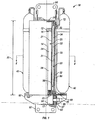
- drill string compensator 10 includes cylinder 20 and accumulator 30.
- Cylinder 20 and accumulator 30 include first closed end 101 and second closed end 102.
- First closed end 101 and second closed end 102 facilitate closing off cylinder 20 and accumulator 30, and thus drill string compensator 10, from atmosphere so that drill string compensator 10 is a closed system.
- First closed end 101 includes first end attachment member 90 to facilitate connecting drill string compensator 10 to a drill string (not shown).
- Cylinder 20 has cylinder inner wall surface 21, cylinder outer wall surface 22, and cylinder cavity 24. Piston 12 and piston rod 14 are slidably engaged within cylinder cavity 24 along inner wall surface 21, thereby dividing cylinder cavity 24 into piston side cavity 26 and rod side cavity 28. Piston 12 is designed such that it is slidably engaged with cylinder 20 by contacting cylinder inner wall surface 21 and preventing fluid communication between piston side cavity 26 and rod side cavity 28, yet piston 12 and piston rod 14 are permitted to move along length 25 of cylinder 20. Seals (not shown) disposed in or around piston 12 may be utilized to prevent fluid communication between piston side cavity 26 and rod side cavity 28.
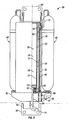
- Piston 12 and piston rod 14, and thus drill string compensator 10 have retracted position (FIG. 1) and a plurality of extended positions, one of the plurality of extended positions being a fully extended position (FIG. 3).
- the fully extended position will be based upon the length of piston rod 14.
- Piston rod 14 includes first piston rod end 16 and second piston rod end 17.
- First piston rod end 16 is connected to piston 12 and second piston rod end 17 is connected to second end attachment member 92 through piston rod passageway disposed through second closed end 102 as discussed in greater detail below.
- Second end attachment member 92 facilitates connecting drill string compensator 10 to a drill string.
- drill string compensator 10 includes main frame 80 and base 82 disposed along second closed end 102 to provide support to cylinder 20, accumulator 30, and air pressure vessel 40.
- Second closed end 102 and base 82 includes piston rod passageway 84 through which rod 14 is permitted to pass to connect to second end attachment member 92.
- Piston rod passageway 84 is designed to prevent fluid communication between rod side cavity 28 and the outside of drill string compensator 10, i.e., atmosphere. Seals (not shown) disposed in or around piston rod 14, or within second closed end 102 or within base 82 along piston rod passageway 84, may be utilized to prevent fluid communication between rod side cavity 28 and the atmosphere. Therefore, drill string compensator 10 provides a closed system, i.e., not open to the atmosphere.
- base 82 includes lock bar assembly 95 having lock bar 97 and lock bar passageway 96 disposed through a portion of base 82.
- Base 82 also includes second end attachment member recess 86 for receiving a portion of second end attachment member 92.
- second end attachment member 92 includes second end attachment member passageway 93 such that when piston rod 14 is placed is a certain position a portion of second end attachment member 92 is disposed within second end attachment member recess 86 such that lock bar passageway 96 and second end attachment member passageway 93 are aligned.
- lock bar 97 is permitted to be actuated within lock bar passageway 96 and second end attachment member passageway 93 to facilitate securing second end attachment member 92 to base 82, and thus piston 12 and piston rod 14, and thus drill string compensator 10, in a desired position, e.g., retracted position shown in FIG. 1.
- Accumulator 30 includes first accumulator inner wall surface 31, second accumulator inner wall surface 33, accumulator outer wall surface 32, and accumulator cavity 34. As shown in FIGS. 1-3, second accumulator inner wall surface 33 and cylinder outer wall surface 22 are integral, i.e., the same wall surface. Additionally, as shown in FIGS. 1-3, in a one specific embodiment, accumulator 30 is concentrically disposed around cylinder 20.
- Accumulator cavity 34 is in fluid communication with rod side cavity 28 through port 60.
- Port 60 preferably includes shut-off valve 50 for facilitating regulation of the movement of hydraulic fluid or gas from rod side cavity 28 to accumulator cavity 34, and vice versa.
- an operator of drill string compensator 10 may place drill string compensator 10 in a desired position, e.g., one of the plurality of extended positions, and shut-off valve 50 may be closed, thereby preventing movement of piston 12 and piston rod 14, and thus drill string compensator 10, to any of the other plurality of extended positions or to the retracted position.
- Accumulator cavity 34 is also in fluid communication with at least one air pressure vessel 40 through port 70.
- air pressure vessel 40 refers to "air,” it is to be understood that any gas, e.g., atmospheric air and nitrogen, as desired or necessary depending on operating conditions, e.g., severe cold, heat, or pressures, may be contained within air pressure vessel 40.
- Each of the at least one air pressure vessels 40 are preferably radially disposed around cylinder 20 and accumulator 30. As shown in FIGS. 1-3, two air pressure vessels 40 are disposed radially around cylinder 20 and accumulator 30. Additionally, port 60 is preferably disposed in close proximity to second closed end 102 and port 70 is preferably disposed in close proximity to first closed end 101. Further, as shown if FIGS. 1 and 3, each air pressure vessel 40 preferably includes air transfer tubing 72 for maintaining air pressure vessel 40 in fluid communication with accumulator 30.
- hydraulic fluid is transported out of accumulator 30, through port 60, and into rod side cavity 28 while air or other gas is transported from air pressure vessel 40, through port 70, and into accumulator 30.
- the invention is directed to methods of compensating a drill string.
- the methods comprise the steps of providing one or more of the embodiments of drill string compensator 10 discussed above.
- Rod side cavity 28 and a portion of accumulator cavity 34 are then filled with portions of hydraulic fluid (not shown) in amounts sufficient to support the weight of the drill string and permit drill string compensator 10 to move from the retracted position to at least one of the plurality of extended positions, and from the at least one of the plurality of extended positions to the retracted position.
- Each of the air pressure vessels 40 is pressurized with a gas pressure sufficient to support the weight of the drill string and permit drill string compensator 10 to move from the retracted position to at least one of the plurality of extended positions and from the at least one of the plurality of extended positions to the retracted position.
- a gas pressure sufficient to support the weight of the drill string and permit drill string compensator 10 to move from the retracted position to at least one of the plurality of extended positions and from the at least one of the plurality of extended positions to the retracted position.
- drill string compensator 10 is then inserted into the drill string.
- drill string compensator 10 is placed and maintained in the retracted position prior to being inserted in the drill string.
- lock bar 97 in drill string compensator 10 may be actuated to maintain drill string compensator 10 in the retracted position.
- shut-off valve 50 maybe actuated to maintain drill string compensator 10 in the retracted position.
- drill string compensator 10 may be placed in any position desired or necessary due to available room constraints to maneuver drill string compensator 10 into place, prior to inserting drill string compensator 10 into the drill string by actuating lock bar 97 or shut-off valve 50.
- additional air pressure vessels may be disposed radially around the cylinder, thereby increasing the maximum load that the drill string compensator can support.
- additional air pressure vessels in fluid communication with air pressure vessel 40 may be located remotely from drill string compensator 10, thereby increasing the maximum load that the drill string compensator can support.
- the drill string compensator may not include a base. Therefore, second closed end includes the piston rod passageway through which the piston rod passes to connect to the second attachment member. As such, seals may be utilized around the piston rod or within second closed end along the piston rod passageway to prevent fluid communication between the rod side cavity and the atmosphere. Accordingly, the invention is therefore to be limited only by the scope of the appended claims.
Landscapes
- Engineering & Computer Science (AREA)
- Geology (AREA)
- Mining & Mineral Resources (AREA)
- Life Sciences & Earth Sciences (AREA)
- General Life Sciences & Earth Sciences (AREA)
- Fluid Mechanics (AREA)
- Mechanical Engineering (AREA)
- Environmental & Geological Engineering (AREA)
- Physics & Mathematics (AREA)
- Geochemistry & Mineralogy (AREA)
- Earth Drilling (AREA)
- Food-Manufacturing Devices (AREA)
- Adornments (AREA)
- Treatment Of Water By Ion Exchange (AREA)
- Perforating, Stamping-Out Or Severing By Means Other Than Cutting (AREA)
Claims (12)
- Geschlossenes Bohrstrangkompensatorsystem (10) mit:- einem Zylinder (20) mit einer Zylinderinnenwandfläche (21), einer Zylinderaußenwandfläche (22) und einem Zylinderhohlraum (24);- einem Kolben (12);- einer Kolbenstange (14) mit einem ersten Kolbenstangenende (16) und einem zweiten Kolbenstangenende (17), wobei das erste Kolbenstangenende (16) mit dem Kolben (12) verbunden ist, der Kolben (12) und die Kolbenstange (14) gleitbar innerhalb des Zylinderhohlraums (24) im Eingriff sind, wodurch der Zylinderhohlraum (24) in einen stangenseitigen Hohlraum (28), der einen ersten Anteil eines Hydraulikfluids enthält, das darin unter Druck angeordnet ist, und in einen kolbenseitigen Hohlraum (26) unterteilt ist, wobei der Kolben (12) und die Kolbenstange (14) jeweils eine eingezogene Stellung und eine Vielzahl gestreckter Stellungen aufweisen;- einem den Zylinder (20) umgebenden Sammelbehälter (30) mit einer ersten Sammelbehälterinnenwandfläche (31), einer zweiten Sammelbehälterinnenwandfläche (33), einer Sammelbehälteraußenwandfläche (32) und einem Sammelbehälterhohlraum (34), wobei der Sammelbehälterhohlraum (34) in einer Fluidverbindung mit dem stangenseitigen Hohlraum (28) steht und der Sammelbehälterhohlraum (34) einen zweiten Anteil des Hydraulikfluids und ein unter Druck stehendes Gas enthält, wobei der Zylinder (20) und der Sammelbehälter (30) ein erstes geschlossenes Ende (101) und ein zweites geschlossenes Ende (102) aufweisen, das erste geschlossene Ende (101) ein Befestigungselement (90) an dem ersten Ende aufweist und das zweite geschlossene Ende (102) eine Kolbenstangendurchführung aufweist, durch die das zweite Kolbenstangenende (17) hindurchgeht, und das zweite Kolbenstangenende (17) mit einem Befestigungselement (92) an dem zweiten Ende verbunden ist; und- zumindest einem radial um den Zylinder (20) und den Sammelbehälter (30) angeordneten Druckluftbehälter (40), wobei der oder jeder Druckluftbehälter in einer Fluidverbindung mit dem Sammelbehälterhohlraum (34) steht, wobei der stangenseitige Hohlraum (28) in einer Fluidverbindung mit dem Sammelbehälterhohlraum (34) durch einen Anschluss (60) steht und der Anschluss (60) ein Absperrventil (50) enthält.
- Geschlossenes Bohrstrangkompensatorsystem (10) nach Anspruch 1, bei dem die Zylinderaußenwandfläche (22) und die erste Sammelbehälterinnenwandfläche (31) einstückig sind.
- Geschlossenes Bohrstrangkompensatorsystem (10) nach Anspruch 1 oder 2, bei dem der kolbenseitige Hohlraum (26) ein Vakuum ist.
- Geschlossenes Bohrstrangkompensatorsystem (10) nach einem der vorstehenden Ansprüche, bei dem der oder jeder Druckluftbehälter (40) in einer Fluidverbindung mit dem Sammelbehälterhohlraum (34) durch einen zweiten Anschluss (70) steht und bei dem der erste Anschluss (60) in der Nähe des zweiten Endes (102) des Bohrstrangkompensators (10) angeordnet ist und der zweite Anschluss (70) in der Nähe des ersten Endes (101) des Bohrstrangkompensators (10) angeordnet ist.
- Geschlossenes Bohrstrangkompensatorsystem (10) nach einem der vorstehenden Ansprüche, bei dem das zweite Ende (102) ein Grundelement (82) mit einer Sperrriegelanordnung (95) zum Sichern des Bohrstrangkompensators (10) in der eingezogenen Stellung aufweist.
- Geschlossenes Bohrstrangkompensatorsystem (10) nach Anspruch 5, bei dem das Befestigungselement (92) an dem zweiten Ende eine Befestigungselementdurchführung (93) an dem zweiten Ende durch zumindest einen Teil des Befestigungselementes (92) an dem zweiten Ende aufweist und das Grundelement (82) eine Sperrriegeldurchführung (96) durch zumindest einen Teil des Grundelementes (82) aufweist, wobei die Befestigungselementdurchführung (93) an dem zweiten Ende und die Sperrriegeldurchführung (96) miteinander in der eingezogenen Stellung zum Aufnehmen eines Sperrriegels (97) durch die Befestigungselementdurchführung (93) an dem zweiten Ende und die Sperrriegeldurchführung (96) zum Sichern des Bohrstrangkompensators (10) in der eingezogenen Stellung abgleichbar sind.
- Geschlossenes Bohrstrangkompensatorsystem (10) nach Anspruch 6, bei dem das erste Ende (101) und das zweite Ende (102) durch eine Hauptrahmenanordnung (80) verbunden sind.
- Geschlossenes Bohrstrangkompensatorsystem (10) nach Anspruch 7, bei dem das Grundelement (82) mit der Hauptrahmenanordnung (80) verbunden ist.
- Geschlossenes Bohrstrangkompensatorsystem (10) nach einem der vorstehenden Ansprüche, bei dem der Zylinder (20) und der Sammelbehälter (30) konzentrisch sind.
- Verfahren zum Kompensieren eines Bohrstrangs mit den Schritten:- Bereitstellen eines geschlossenen Bohrstrangkompensatorsystems (10) mit: einem Zylinder (20) mit einer Zylinderinnenwandfläche. (21), einer Zylinderaußenwandfläche (22) und einem Zylinderhohlraum (24); einem Kolben (12); einer Kolbenstange (14) mit einem ersten Kolbenstangenende (16) und einem zweiten Kolbenstangenende (17), wobei das erste Kolbenstangenende (16) mit dem Kolben (12) verbunden wird, der Kolben (12) und die Kolbenstange (14) gleitbar innerhalb des Zylinderhohlraums (24) im Eingriff sind, wodurch der Zylinderhohlraum (24) in einen stangenseitigen Hohlraum (28), der einen ersten Anteil eines Hydraulikfluids enthält, das darin unter Druck angeordnet wird, und in einen kolbenseitigen Hohlraum (26) unterteilt werden, wobei der Kolben (12) und die Kolbenstange (14) jeweils eine eingezogene Stellung und eine Vielzahl gestreckter Stellungen aufweisen; einem den Zylinder (20) umgebenden Sammelbehälter (30) mit einer ersten Sammelbehälterinnenwandfläche (31), einer zweiten Sammelbehälterinnenwandfläche (33), einer Sammelbehälteraußenwandfläche (32) und einem Sammelbehälterhohlraum (34), wobei der Sammelbehälterhohlraum (34) in einer Fluidverbindung mit dem stangenseitigen Hohlraum (28) steht und der Sammelbehälterhohlraum (34) einen zweiten Anteil des Hydraulikfluids und ein unter Druck stehendes Gas enthält, wobei der Zylinder (20) und der Sammelbehälter (30) ein erstes geschlossenes Ende (101) und ein zweites geschlossenes Ende (102) aufweisen, das erste geschlossene Ende (101) ein erstes Befestigungselement (90) an dem ersten Ende aufweist und das zweite geschlossene Ende (102) eine Kolbenstangendurchführung aufweist, durch die das zweite Kolbenstangenende (17) hindurchgeht, und das zweite Kolbenstangenende (17) mit einem Befestigungselement (92) an dem zweiten Ende verbunden wird; und zumindest einem radial um den Zylinder (20) und dem Sammelbehälter (30) angeordneten Druckluftbehälter (40), wobei der oder jeder Druckluftbehälter in einer Fluidverbindung mit dem Sammelbehälterhohlraum (34) steht;- Füllen des stangenseitigen Hohlraums (28) und eines Teils des Sammelbehälterhohlraums (34) mit dem ersten Anteil des Hydraulikfluids und dem zweiten Anteil des Hydraulikfluids in einer ausreichenden Menge, um das Gewicht des Bohrstrangs zu tragen und dem Bohrstrangkompensator (10) zu ermöglichen, sich von der eingezogenen Stellung zu zumindest einen der Vielzahl der gestreckten Stellungen und von der zumindest einen der Vielzahl der gestreckten Stellungen zu der eingezogenen Stellung zu bewegen;- Unterdrucksetzen des oder jedes Druckluftbehälters (40) mit einem ausreichenden Gasdruck, um das Gewicht des Bohrstrangs zu tragen und dem Bohrstrangkompensator (10) zu ermöglichen, sich von der angezogenen Stellung zu zumindest einer der Vielzahl der gestreckten Stellungen und von der zumindest einen der Vielzahl der gestreckten Stellungen zu der eingezogenen Stellung zu bewegen; und- Einfügen des Bohrstrangkompensators (10) in den Bohrstrang, wobei der Sammelbehälter (30) und der stangenseitige Hohlraum (28) des Zylinders (20) des Bohrstrangkompensators (10) in Fluidverbindung miteinander durch einen Anschluss (60) stehen, wobei der Anschluss (60) ein darin angeordnetes Absperrventil (50) aufweist und der Bohrstrangkompensator (10) in der eingezogenen Stellung durch Betätigen des bsperrventils (50) gehalten wird.
- Verfahren nach Anspruch 10, bei dem der Bohrstrangkompensator (10) in der eingezogenen Stellung angeordnet und gehalten wird, bevor er in den Bohrstrang eingefügt wird.
- Verfahren nach Anspruch 10 oder 11, bei dem der Bohrstrangkompensator (10) in der eingezogenen Stellung durch Betätigen eines Sperrriegels (97) durch das Befestigungselement (92) an dem zweiten Ende gehalten wird.
Applications Claiming Priority (2)
| Application Number | Priority Date | Filing Date | Title |
|---|---|---|---|
| US314747 | 1989-02-24 | ||
| US10/314,747 US6968900B2 (en) | 2002-12-09 | 2002-12-09 | Portable drill string compensator |
Publications (2)
| Publication Number | Publication Date |
|---|---|
| EP1428973A1 EP1428973A1 (de) | 2004-06-16 |
| EP1428973B1 true EP1428973B1 (de) | 2006-05-31 |
Family
ID=30443942
Family Applications (1)
| Application Number | Title | Priority Date | Filing Date |
|---|---|---|---|
| EP03078680A Expired - Lifetime EP1428973B1 (de) | 2002-12-09 | 2003-11-19 | Tragbarer Tauschwingungskompensator |
Country Status (7)
| Country | Link |
|---|---|
| US (2) | US6968900B2 (de) |
| EP (1) | EP1428973B1 (de) |
| AT (1) | ATE328186T1 (de) |
| BR (1) | BRPI0307860B1 (de) |
| DE (1) | DE60305615D1 (de) |
| NO (1) | NO329534B1 (de) |
| SG (1) | SG115591A1 (de) |
Cited By (1)
| Publication number | Priority date | Publication date | Assignee | Title |
|---|---|---|---|---|
| US7819195B2 (en) | 2005-11-16 | 2010-10-26 | Vetco Gray Inc. | External high pressure fluid reservoir for riser tensioner cylinder assembly |
Families Citing this family (28)
| Publication number | Priority date | Publication date | Assignee | Title |
|---|---|---|---|---|
| US7416697B2 (en) | 2002-06-14 | 2008-08-26 | General Electric Company | Method for preparing a metallic article having an other additive constituent, without any melting |
| US7231981B2 (en) * | 2003-10-08 | 2007-06-19 | National Oilwell, L.P. | Inline compensator for a floating drill rig |
| US20050074296A1 (en) * | 2003-10-15 | 2005-04-07 | Mccarty Jeffery Kirk | Hydro-pneumatic tensioner with stiffness altering secondary accumulator |
| US7531021B2 (en) | 2004-11-12 | 2009-05-12 | General Electric Company | Article having a dispersion of ultrafine titanium boride particles in a titanium-base matrix |
| US7823646B2 (en) | 2004-11-19 | 2010-11-02 | Vetco Gray Inc. | Riser tensioner with lubricant reservoir |
| EP2054335B1 (de) * | 2006-08-15 | 2012-04-04 | Hydralift Amclyde, Inc. | Direkt wirkender einzelscheiben-aktiv/passiv-hubkompensator |
| US7520129B2 (en) * | 2006-11-07 | 2009-04-21 | Varco I/P, Inc. | Subsea pressure accumulator systems |
| US7926501B2 (en) * | 2007-02-07 | 2011-04-19 | National Oilwell Varco L.P. | Subsea pressure systems for fluid recovery |
| US8464525B2 (en) * | 2007-02-07 | 2013-06-18 | National Oilwell Varco, L.P. | Subsea power fluid recovery systems |
| US7628224B2 (en) * | 2007-04-30 | 2009-12-08 | Kellogg Brown & Root Llc | Shallow/intermediate water multipurpose floating platform for arctic environments |
| NO330288B1 (no) * | 2008-06-20 | 2011-03-21 | Norocean As | Slippforbindelse med justerbar forspenning |
| US8162062B1 (en) * | 2008-08-28 | 2012-04-24 | Stingray Offshore Solutions, LLC | Offshore well intervention lift frame and method |
| NO332769B2 (no) | 2009-12-15 | 2013-01-14 | Wellpartner As | Anordning ved sikkerhetskopling for rørstrengoppheng |
| US8157013B1 (en) * | 2010-12-08 | 2012-04-17 | Drilling Technological Innovations, LLC | Tensioner system with recoil controls |
| US8517110B2 (en) | 2011-05-17 | 2013-08-27 | Drilling Technology Innovations, LLC | Ram tensioner system |
| EP2797830B1 (de) | 2011-12-30 | 2016-03-09 | National Oilwell Varco, L.P. | Tiefwasser-gelenkauslegerkran |
| NO334005B1 (no) | 2012-03-12 | 2013-11-11 | Depro As | Anordning for kompensasjon av bølgebevirkede avstandsvariasjoner på borestreng |
| CN102587871B (zh) * | 2012-03-26 | 2014-12-31 | 张玉锐 | 游梁式抽油机全平衡节能装置 |
| WO2013154566A1 (en) * | 2012-04-12 | 2013-10-17 | Eaton Corporation | Plunger-type wire riser tensioner |
| BR112015013690B1 (pt) | 2012-12-13 | 2021-11-16 | National Oilwell Varco, L.P. | Sistema de compensação de balouço remoto e guindaste tendo um sistema de compensação de balouço |
| US9725968B2 (en) | 2013-07-15 | 2017-08-08 | Canrig Drilling Technology Ltd. | Force application reduction employing actuator and thrust bearing |
| NO20131234A1 (no) * | 2013-09-12 | 2015-03-13 | Depro As | Anordning for datastyrt kompensasjon av bølgebevirkede avstandsvariasjoner på borestreng |
| US8757205B1 (en) | 2013-11-22 | 2014-06-24 | Drilling Technological Innovations, LLC | Choke assembly tensioner system for a drilling rig |
| US8757204B1 (en) | 2013-11-22 | 2014-06-24 | Drilling Technological Innovations, LLC | Riser recoil valve |
| AU2014221196B2 (en) * | 2014-09-02 | 2016-07-07 | Icon Engineering Pty Ltd | Coiled tubing lift frame assembly and method of use thereof |
| US10174566B2 (en) * | 2016-03-02 | 2019-01-08 | Vetco Gray, LLC | Inverted pull-up riser tensioner |
| US9816538B1 (en) * | 2016-08-31 | 2017-11-14 | Vetco Gray Inc. | Tensioner cylinder with internal gas bladder in high pressure chamber |
| CN113188888A (zh) * | 2021-04-21 | 2021-07-30 | 西安恒热热力技术有限责任公司 | 一种检测补偿器耐压性能的检测设备及检测方法 |
Family Cites Families (65)
| Publication number | Priority date | Publication date | Assignee | Title |
|---|---|---|---|---|
| US913970A (en) * | 1902-08-09 | 1909-03-02 | Pittsburg Pneumatic Company | Fluid-pressure ram. |
| US3280908A (en) * | 1962-05-21 | 1966-10-25 | Fmc Corp | Apparatus for underwater drilling and well completion |
| US3208728A (en) * | 1962-11-19 | 1965-09-28 | Exxon Production Research Co | Apparatus for use on floating drilling platforms |
| US3313345A (en) * | 1964-06-02 | 1967-04-11 | Chevron Res | Method and apparatus for offshore drilling and well completion |
| US3643751A (en) * | 1969-12-15 | 1972-02-22 | Charles D Crickmer | Hydrostatic riser pipe tensioner |
| US3718316A (en) * | 1970-09-04 | 1973-02-27 | Vetco Offshore Ind Inc | Hydraulic-pneumatic weight control and compensating apparatus |
| US3680644A (en) * | 1970-12-28 | 1972-08-01 | Santa Fe Int Corp | Pile driving system and apparatus |
| US3793835A (en) * | 1972-02-02 | 1974-02-26 | Vetco Offshore Ind Inc | Variable rate hydraulic-pneumatic weight control and compensating apparatus |
| US3804183A (en) * | 1972-05-01 | 1974-04-16 | Rucker Co | Drill string compensator |
| US3841607A (en) * | 1972-07-25 | 1974-10-15 | Vetco Offshore Ind Inc | Hydraulic motion compensating apparatus |
| US3897045A (en) * | 1973-09-12 | 1975-07-29 | Vetco Offshore Ind Inc | Riser pipe and guide line tensioning apparatus |
| US3955621A (en) * | 1975-02-14 | 1976-05-11 | Houston Engineers, Inc. | Riser assembly |
| US4004532A (en) * | 1975-05-05 | 1977-01-25 | Western Gear Corporation | Riser tension system for floating platform |
| US4068868A (en) * | 1975-09-02 | 1978-01-17 | Vetco Offshore Industries, Inc. | Flexible joints for marine risers |
| US4075858A (en) * | 1976-05-17 | 1978-02-28 | Frederick Leonard L | Hydraulic pile driving apparatus and method |
| GB1600740A (en) * | 1977-04-23 | 1981-10-21 | Brown Bros & Co Ltd | Tensioner device for offshore oil production and exploration platfroms |
| US4222341A (en) * | 1978-01-11 | 1980-09-16 | Western Gear Corporation | Riser tensioning wave and tide compensating system for a floating platform |
| US4176722A (en) * | 1978-03-15 | 1979-12-04 | Global Marine, Inc. | Marine riser system with dual purpose lift and heave compensator mechanism |
| US4351261A (en) * | 1978-05-01 | 1982-09-28 | Sedco, Inc. | Riser recoil preventer system |
| US4272059A (en) * | 1978-06-16 | 1981-06-09 | Exxon Production Research Company | Riser tensioner system |
| US4317586A (en) * | 1979-01-25 | 1982-03-02 | Campbell Joseph K | Pipe stress/strain neutralizer |
| US4379657A (en) * | 1980-06-19 | 1983-04-12 | Conoco Inc. | Riser tensioner |
| US4362438A (en) * | 1980-10-03 | 1982-12-07 | A/S Akers Mek. Verksted | Supporting device |
| DE3047375C2 (de) * | 1980-12-16 | 1985-09-05 | Koehring Gmbh, 2000 Hamburg | Tauchfähige Rammvorrichtung |
| US4449854A (en) * | 1981-02-12 | 1984-05-22 | Nl Industries, Inc. | Motion compensator system |
| US4367981A (en) * | 1981-06-29 | 1983-01-11 | Combustion Engineering, Inc. | Fluid pressure-tensioned slip joint for drilling riser |
| US4432420A (en) * | 1981-08-06 | 1984-02-21 | Exxon Production Research Co. | Riser tensioner safety system |
| US4423983A (en) * | 1981-08-14 | 1984-01-03 | Sedco-Hamilton Production Services | Marine riser system |
| US4421173A (en) * | 1981-08-20 | 1983-12-20 | Nl Industries, Inc. | Motion compensator with improved position indicator |
| JPS59177494A (ja) * | 1983-03-29 | 1984-10-08 | 工業技術院長 | ライザ用テレスコピツクジヨイント |
| US4501219A (en) * | 1983-04-04 | 1985-02-26 | Nl Industries, Inc. | Tensioner apparatus with emergency limit means |
| US4473323A (en) * | 1983-04-14 | 1984-09-25 | Exxon Production Research Co. | Buoyant arm for maintaining tension on a drilling riser |
| NO842405L (no) | 1983-06-17 | 1985-03-27 | Novacorp Int Consulting Ltd | Anordning og fremgangsmaate for fortoeyning av et hydrokarbon-produksjonssystem tilknyttet et skip |
| US4638978A (en) * | 1983-07-22 | 1987-01-27 | Jordan Larry B | Hydropneumatic cable tensioner |
| US4712620A (en) * | 1985-01-31 | 1987-12-15 | Vetco Gray Inc. | Upper marine riser package |
| US4799827A (en) * | 1986-11-17 | 1989-01-24 | Vetco Gray Inc. | Modular riser tensioner incorporating integral hydraulic cylinder accumulator units |
| US4787778A (en) * | 1986-12-01 | 1988-11-29 | Conoco Inc. | Method and apparatus for tensioning a riser |
| CA1259232A (en) * | 1986-12-24 | 1989-09-12 | Nikolai P. Ermilov | Percussive tool |
| US4883387A (en) * | 1987-04-24 | 1989-11-28 | Conoco, Inc. | Apparatus for tensioning a riser |
| US4808035A (en) * | 1987-05-13 | 1989-02-28 | Exxon Production Research Company | Pneumatic riser tensioner |
| US4886397A (en) * | 1987-08-27 | 1989-12-12 | Cherbonnier T Dave | Dynamic load compensating system |
| SK279150B6 (sk) * | 1990-11-09 | 1998-07-08 | Permon | Pneumatické ponorné vŕtacie náradie |
| GB2250763B (en) * | 1990-12-13 | 1995-08-02 | Ltv Energy Prod Co | Riser tensioner system for use on offshore platforms using elastomeric pads or helical metal compression springs |
| US5101905A (en) * | 1991-02-26 | 1992-04-07 | Ltv Energy Products Company | Riser tensioner system for use on offshore platforms |
| US5169265A (en) * | 1991-09-27 | 1992-12-08 | Paul-Munroe Hydraulics, Inc. | Passive fire protection system for marine risers |
| US5209302A (en) * | 1991-10-04 | 1993-05-11 | Retsco, Inc. | Semi-active heave compensation system for marine vessels |
| US5252004A (en) * | 1992-07-13 | 1993-10-12 | Paul-Munroe Engineering | Rod accumulator riser tensioning cylinder assembly |
| US5392853A (en) * | 1992-11-25 | 1995-02-28 | Solinst Canada Ltd. | Plugging system for boreholes |
| DE4419499A1 (de) * | 1994-06-03 | 1995-12-07 | Interoc Vertriebsgesellschaft | Hydraulisches Schlaggerät mit stufenlos regelbarer Schlagzahl und Schlagenergie |
| US5551803A (en) * | 1994-10-05 | 1996-09-03 | Abb Vetco Gray, Inc. | Riser tensioning mechanism for floating platforms |
| NO302493B1 (no) | 1996-05-13 | 1998-03-09 | Maritime Hydraulics As | Glideskjöt |
| US5727630A (en) * | 1996-08-09 | 1998-03-17 | Abb Vetco Gray Inc. | Telescopic joint control line system |
| DE19652079C2 (de) * | 1996-12-14 | 1999-02-25 | Krupp Berco Bautechnik Gmbh | Fluidbetriebenes Schlagwerk |
| US5758990A (en) * | 1997-02-21 | 1998-06-02 | Deep Oil Technology, Incorporated | Riser tensioning device |
| US5846028A (en) * | 1997-08-01 | 1998-12-08 | Hydralift, Inc. | Controlled pressure multi-cylinder riser tensioner and method |
| US5951061A (en) * | 1997-08-13 | 1999-09-14 | Continental Emsco Company | Elastomeric subsea flex joint and swivel for offshore risers |
| NL1007798C2 (nl) * | 1997-12-15 | 1999-06-23 | Huisman Spec Lifting Equip Bv | Riser-tensioner. |
| FI105594B (fi) * | 1998-02-05 | 2000-09-15 | Tamrock Oy | Sovitelma hydraulisen rikotuslaitteen huollon tarpeen tunnistamiseksi |
| FI107891B (fi) * | 1998-03-30 | 2001-10-31 | Sandvik Tamrock Oy | Painenestekäyttöinen iskulaite |
| US6068066A (en) * | 1998-08-20 | 2000-05-30 | Byrt; Harry F. | Hydraulic drilling rig |
| US6173781B1 (en) | 1998-10-28 | 2001-01-16 | Deep Vision Llc | Slip joint intervention riser with pressure seals and method of using the same |
| US6419277B1 (en) * | 1999-10-29 | 2002-07-16 | Hydril Company | Conduit section having threaded section connectors and external conduits attached thereto |
| US6343893B1 (en) * | 1999-11-29 | 2002-02-05 | Mercur Slimhole Drilling And Intervention As | Arrangement for controlling floating drilling and intervention vessels |
| US6431284B1 (en) * | 2000-10-03 | 2002-08-13 | Cso Aker Maritime, Inc. | Gimbaled table riser support system |
| FI112450B (fi) | 2000-10-09 | 2003-12-15 | Sandvik Tamrock Oy | Rikotuslaite ja työkalu |
-
2002
- 2002-12-09 US US10/314,747 patent/US6968900B2/en not_active Expired - Lifetime
-
2003
- 2003-11-19 DE DE60305615T patent/DE60305615D1/de not_active Expired - Lifetime
- 2003-11-19 AT AT03078680T patent/ATE328186T1/de not_active IP Right Cessation
- 2003-11-19 EP EP03078680A patent/EP1428973B1/de not_active Expired - Lifetime
- 2003-11-19 SG SG200306898A patent/SG115591A1/en unknown
- 2003-11-28 NO NO20035286A patent/NO329534B1/no not_active IP Right Cessation
- 2003-12-01 BR BRPI0307860A patent/BRPI0307860B1/pt active IP Right Grant
-
2005
- 2005-07-15 US US11/182,636 patent/US7131496B2/en not_active Expired - Lifetime
Cited By (1)
| Publication number | Priority date | Publication date | Assignee | Title |
|---|---|---|---|---|
| US7819195B2 (en) | 2005-11-16 | 2010-10-26 | Vetco Gray Inc. | External high pressure fluid reservoir for riser tensioner cylinder assembly |
Also Published As
| Publication number | Publication date |
|---|---|
| US6968900B2 (en) | 2005-11-29 |
| US7131496B2 (en) | 2006-11-07 |
| NO329534B1 (no) | 2010-11-08 |
| NO20035286D0 (no) | 2003-11-28 |
| DE60305615D1 (de) | 2006-07-06 |
| EP1428973A1 (de) | 2004-06-16 |
| NO20035286L (no) | 2004-06-10 |
| US20040108117A1 (en) | 2004-06-10 |
| BR0307860A (pt) | 2004-12-07 |
| BRPI0307860B1 (pt) | 2017-02-21 |
| US20050247452A1 (en) | 2005-11-10 |
| SG115591A1 (en) | 2005-10-28 |
| ATE328186T1 (de) | 2006-06-15 |
Similar Documents
| Publication | Publication Date | Title |
|---|---|---|
| EP1428973B1 (de) | Tragbarer Tauschwingungskompensator | |
| US5069488A (en) | Method and a device for movement-compensation in riser pipes | |
| US4432420A (en) | Riser tensioner safety system | |
| US4487150A (en) | Riser recoil preventer system | |
| US7112011B2 (en) | Hydro-pneumatic tensioner with stiffness altering secondary accumulator | |
| US7686544B2 (en) | Method and arrangement by a workover riser connection | |
| CA2541168C (en) | Inline compensator for a floating drilling rig | |
| US4858694A (en) | Heave compensated stabbing and landing tool | |
| US9359837B2 (en) | Multi capacity riser tensioners | |
| US8684090B2 (en) | Slip connection with adjustable pre-tensioning | |
| NO20111616A1 (no) | Trykkskjot | |
| AU2023200587B2 (en) | Compensated Elevator Link | |
| US20170009537A1 (en) | Compact compensating cylinder | |
| US6835026B2 (en) | Riser tensioning arrangement | |
| EP1266118B1 (de) | Spannvorrichtung und dünungskompensatoren an einem steigrohr | |
| NZ747890A (en) | Compensated Elevator Link |
Legal Events
| Date | Code | Title | Description |
|---|---|---|---|
| PUAI | Public reference made under article 153(3) epc to a published international application that has entered the european phase |
Free format text: ORIGINAL CODE: 0009012 |
|
| AK | Designated contracting states |
Kind code of ref document: A1 Designated state(s): AT BE BG CH CY CZ DE DK EE ES FI FR GB GR HU IE IT LI LU MC NL PT RO SE SI SK TR |
|
| AX | Request for extension of the european patent |
Extension state: AL LT LV MK |
|
| 17P | Request for examination filed |
Effective date: 20041213 |
|
| AKX | Designation fees paid |
Designated state(s): AT BE BG CH CY CZ DE DK EE ES FI FR GB GR HU IE IT LI LU MC NL PT RO SE SI SK TR |
|
| 17Q | First examination report despatched |
Effective date: 20050331 |
|
| GRAP | Despatch of communication of intention to grant a patent |
Free format text: ORIGINAL CODE: EPIDOSNIGR1 |
|
| GRAS | Grant fee paid |
Free format text: ORIGINAL CODE: EPIDOSNIGR3 |
|
| GRAA | (expected) grant |
Free format text: ORIGINAL CODE: 0009210 |
|
| AK | Designated contracting states |
Kind code of ref document: B1 Designated state(s): AT BE BG CH CY CZ DE DK EE ES FI FR GB GR HU IE IT LI LU MC NL PT RO SE SI SK TR |
|
| PG25 | Lapsed in a contracting state [announced via postgrant information from national office to epo] |
Ref country code: IT Free format text: LAPSE BECAUSE OF FAILURE TO SUBMIT A TRANSLATION OF THE DESCRIPTION OR TO PAY THE FEE WITHIN THE PRESCRIBED TIME-LIMIT;WARNING: LAPSES OF ITALIAN PATENTS WITH EFFECTIVE DATE BEFORE 2007 MAY HAVE OCCURRED AT ANY TIME BEFORE 2007. THE CORRECT EFFECTIVE DATE MAY BE DIFFERENT FROM THE ONE RECORDED. Effective date: 20060531 Ref country code: FI Free format text: LAPSE BECAUSE OF FAILURE TO SUBMIT A TRANSLATION OF THE DESCRIPTION OR TO PAY THE FEE WITHIN THE PRESCRIBED TIME-LIMIT Effective date: 20060531 Ref country code: CH Free format text: LAPSE BECAUSE OF FAILURE TO SUBMIT A TRANSLATION OF THE DESCRIPTION OR TO PAY THE FEE WITHIN THE PRESCRIBED TIME-LIMIT Effective date: 20060531 Ref country code: AT Free format text: LAPSE BECAUSE OF FAILURE TO SUBMIT A TRANSLATION OF THE DESCRIPTION OR TO PAY THE FEE WITHIN THE PRESCRIBED TIME-LIMIT Effective date: 20060531 Ref country code: NL Free format text: LAPSE BECAUSE OF FAILURE TO SUBMIT A TRANSLATION OF THE DESCRIPTION OR TO PAY THE FEE WITHIN THE PRESCRIBED TIME-LIMIT Effective date: 20060531 Ref country code: LI Free format text: LAPSE BECAUSE OF FAILURE TO SUBMIT A TRANSLATION OF THE DESCRIPTION OR TO PAY THE FEE WITHIN THE PRESCRIBED TIME-LIMIT Effective date: 20060531 Ref country code: SI Free format text: LAPSE BECAUSE OF FAILURE TO SUBMIT A TRANSLATION OF THE DESCRIPTION OR TO PAY THE FEE WITHIN THE PRESCRIBED TIME-LIMIT Effective date: 20060531 Ref country code: BE Free format text: LAPSE BECAUSE OF FAILURE TO SUBMIT A TRANSLATION OF THE DESCRIPTION OR TO PAY THE FEE WITHIN THE PRESCRIBED TIME-LIMIT Effective date: 20060531 Ref country code: RO Free format text: LAPSE BECAUSE OF FAILURE TO SUBMIT A TRANSLATION OF THE DESCRIPTION OR TO PAY THE FEE WITHIN THE PRESCRIBED TIME-LIMIT Effective date: 20060531 Ref country code: SK Free format text: LAPSE BECAUSE OF FAILURE TO SUBMIT A TRANSLATION OF THE DESCRIPTION OR TO PAY THE FEE WITHIN THE PRESCRIBED TIME-LIMIT Effective date: 20060531 Ref country code: CZ Free format text: LAPSE BECAUSE OF FAILURE TO SUBMIT A TRANSLATION OF THE DESCRIPTION OR TO PAY THE FEE WITHIN THE PRESCRIBED TIME-LIMIT Effective date: 20060531 |
|
| REG | Reference to a national code |
Ref country code: GB Ref legal event code: FG4D Ref country code: CH Ref legal event code: EP |
|
| REG | Reference to a national code |
Ref country code: IE Ref legal event code: FG4D |
|
| REF | Corresponds to: |
Ref document number: 60305615 Country of ref document: DE Date of ref document: 20060706 Kind code of ref document: P |
|
| PG25 | Lapsed in a contracting state [announced via postgrant information from national office to epo] |
Ref country code: DK Free format text: LAPSE BECAUSE OF FAILURE TO SUBMIT A TRANSLATION OF THE DESCRIPTION OR TO PAY THE FEE WITHIN THE PRESCRIBED TIME-LIMIT Effective date: 20060831 Ref country code: SE Free format text: LAPSE BECAUSE OF FAILURE TO SUBMIT A TRANSLATION OF THE DESCRIPTION OR TO PAY THE FEE WITHIN THE PRESCRIBED TIME-LIMIT Effective date: 20060831 |
|
| PG25 | Lapsed in a contracting state [announced via postgrant information from national office to epo] |
Ref country code: DE Free format text: LAPSE BECAUSE OF FAILURE TO SUBMIT A TRANSLATION OF THE DESCRIPTION OR TO PAY THE FEE WITHIN THE PRESCRIBED TIME-LIMIT Effective date: 20060901 |
|
| PG25 | Lapsed in a contracting state [announced via postgrant information from national office to epo] |
Ref country code: ES Free format text: LAPSE BECAUSE OF FAILURE TO SUBMIT A TRANSLATION OF THE DESCRIPTION OR TO PAY THE FEE WITHIN THE PRESCRIBED TIME-LIMIT Effective date: 20060911 |
|
| PG25 | Lapsed in a contracting state [announced via postgrant information from national office to epo] |
Ref country code: PT Free format text: LAPSE BECAUSE OF FAILURE TO SUBMIT A TRANSLATION OF THE DESCRIPTION OR TO PAY THE FEE WITHIN THE PRESCRIBED TIME-LIMIT Effective date: 20061031 |
|
| NLV1 | Nl: lapsed or annulled due to failure to fulfill the requirements of art. 29p and 29m of the patents act | ||
| PG25 | Lapsed in a contracting state [announced via postgrant information from national office to epo] |
Ref country code: IE Free format text: LAPSE BECAUSE OF NON-PAYMENT OF DUE FEES Effective date: 20061120 |
|
| PG25 | Lapsed in a contracting state [announced via postgrant information from national office to epo] |
Ref country code: MC Free format text: LAPSE BECAUSE OF NON-PAYMENT OF DUE FEES Effective date: 20061130 |
|
| REG | Reference to a national code |
Ref country code: CH Ref legal event code: PL |
|
| PLBE | No opposition filed within time limit |
Free format text: ORIGINAL CODE: 0009261 |
|
| STAA | Information on the status of an ep patent application or granted ep patent |
Free format text: STATUS: NO OPPOSITION FILED WITHIN TIME LIMIT |
|
| EN | Fr: translation not filed | ||
| 26N | No opposition filed |
Effective date: 20070301 |
|
| PG25 | Lapsed in a contracting state [announced via postgrant information from national office to epo] |
Ref country code: GR Free format text: LAPSE BECAUSE OF FAILURE TO SUBMIT A TRANSLATION OF THE DESCRIPTION OR TO PAY THE FEE WITHIN THE PRESCRIBED TIME-LIMIT Effective date: 20060901 Ref country code: FR Free format text: LAPSE BECAUSE OF FAILURE TO SUBMIT A TRANSLATION OF THE DESCRIPTION OR TO PAY THE FEE WITHIN THE PRESCRIBED TIME-LIMIT Effective date: 20070309 |
|
| PG25 | Lapsed in a contracting state [announced via postgrant information from national office to epo] |
Ref country code: EE Free format text: LAPSE BECAUSE OF FAILURE TO SUBMIT A TRANSLATION OF THE DESCRIPTION OR TO PAY THE FEE WITHIN THE PRESCRIBED TIME-LIMIT Effective date: 20060531 Ref country code: BG Free format text: LAPSE BECAUSE OF FAILURE TO SUBMIT A TRANSLATION OF THE DESCRIPTION OR TO PAY THE FEE WITHIN THE PRESCRIBED TIME-LIMIT Effective date: 20060831 |
|
| PG25 | Lapsed in a contracting state [announced via postgrant information from national office to epo] |
Ref country code: LU Free format text: LAPSE BECAUSE OF NON-PAYMENT OF DUE FEES Effective date: 20061119 Ref country code: TR Free format text: LAPSE BECAUSE OF FAILURE TO SUBMIT A TRANSLATION OF THE DESCRIPTION OR TO PAY THE FEE WITHIN THE PRESCRIBED TIME-LIMIT Effective date: 20060531 Ref country code: HU Free format text: LAPSE BECAUSE OF FAILURE TO SUBMIT A TRANSLATION OF THE DESCRIPTION OR TO PAY THE FEE WITHIN THE PRESCRIBED TIME-LIMIT Effective date: 20061201 |
|
| PG25 | Lapsed in a contracting state [announced via postgrant information from national office to epo] |
Ref country code: FR Free format text: LAPSE BECAUSE OF FAILURE TO SUBMIT A TRANSLATION OF THE DESCRIPTION OR TO PAY THE FEE WITHIN THE PRESCRIBED TIME-LIMIT Effective date: 20060531 Ref country code: CY Free format text: LAPSE BECAUSE OF FAILURE TO SUBMIT A TRANSLATION OF THE DESCRIPTION OR TO PAY THE FEE WITHIN THE PRESCRIBED TIME-LIMIT Effective date: 20060531 |
|
| PGFP | Annual fee paid to national office [announced via postgrant information from national office to epo] |
Ref country code: GB Payment date: 20221125 Year of fee payment: 20 |
|
| REG | Reference to a national code |
Ref country code: GB Ref legal event code: PE20 Expiry date: 20231118 |
|
| PG25 | Lapsed in a contracting state [announced via postgrant information from national office to epo] |
Ref country code: GB Free format text: LAPSE BECAUSE OF EXPIRATION OF PROTECTION Effective date: 20231118 |
|
| PG25 | Lapsed in a contracting state [announced via postgrant information from national office to epo] |
Ref country code: GB Free format text: LAPSE BECAUSE OF EXPIRATION OF PROTECTION Effective date: 20231118 |