EP1428934B1 - Vorrichtung zum Verbinden eines Rohrnetzes in einer Fahrbahn und Anwendungsverfahren - Google Patents
Vorrichtung zum Verbinden eines Rohrnetzes in einer Fahrbahn und Anwendungsverfahren Download PDFInfo
- Publication number
- EP1428934B1 EP1428934B1 EP03078875A EP03078875A EP1428934B1 EP 1428934 B1 EP1428934 B1 EP 1428934B1 EP 03078875 A EP03078875 A EP 03078875A EP 03078875 A EP03078875 A EP 03078875A EP 1428934 B1 EP1428934 B1 EP 1428934B1
- Authority
- EP
- European Patent Office
- Prior art keywords
- pipe
- distribution
- container
- cover
- outer end
- Prior art date
- Legal status (The legal status is an assumption and is not a legal conclusion. Google has not performed a legal analysis and makes no representation as to the accuracy of the status listed.)
- Expired - Lifetime
Links
- 238000000034 method Methods 0.000 title claims description 12
- 230000008878 coupling Effects 0.000 claims description 9
- 238000010168 coupling process Methods 0.000 claims description 9
- 238000005859 coupling reaction Methods 0.000 claims description 9
- 125000006850 spacer group Chemical group 0.000 claims description 3
- 229920003023 plastic Polymers 0.000 claims description 2
- 239000004033 plastic Substances 0.000 claims description 2
- 239000004698 Polyethylene Substances 0.000 description 3
- 238000010276 construction Methods 0.000 description 3
- 238000000465 moulding Methods 0.000 description 3
- -1 polyethylene Polymers 0.000 description 3
- 229920000573 polyethylene Polymers 0.000 description 3
- XLYOFNOQVPJJNP-UHFFFAOYSA-N water Substances O XLYOFNOQVPJJNP-UHFFFAOYSA-N 0.000 description 3
- 230000000712 assembly Effects 0.000 description 1
- 238000000429 assembly Methods 0.000 description 1
- 238000004519 manufacturing process Methods 0.000 description 1
- 238000003801 milling Methods 0.000 description 1
- 230000035515 penetration Effects 0.000 description 1
- 239000004575 stone Substances 0.000 description 1
Images



Classifications
-
- F—MECHANICAL ENGINEERING; LIGHTING; HEATING; WEAPONS; BLASTING
- F24—HEATING; RANGES; VENTILATING
- F24D—DOMESTIC- OR SPACE-HEATING SYSTEMS, e.g. CENTRAL HEATING SYSTEMS; DOMESTIC HOT-WATER SUPPLY SYSTEMS; ELEMENTS OR COMPONENTS THEREFOR
- F24D19/00—Details
-
- E—FIXED CONSTRUCTIONS
- E01—CONSTRUCTION OF ROADS, RAILWAYS, OR BRIDGES
- E01C—CONSTRUCTION OF, OR SURFACES FOR, ROADS, SPORTS GROUNDS, OR THE LIKE; MACHINES OR AUXILIARY TOOLS FOR CONSTRUCTION OR REPAIR
- E01C11/00—Details of pavings
- E01C11/24—Methods or arrangements for preventing slipperiness or protecting against influences of the weather
- E01C11/26—Permanently installed heating or blowing devices ; Mounting thereof
-
- F—MECHANICAL ENGINEERING; LIGHTING; HEATING; WEAPONS; BLASTING
- F24—HEATING; RANGES; VENTILATING
- F24D—DOMESTIC- OR SPACE-HEATING SYSTEMS, e.g. CENTRAL HEATING SYSTEMS; DOMESTIC HOT-WATER SUPPLY SYSTEMS; ELEMENTS OR COMPONENTS THEREFOR
- F24D19/00—Details
- F24D19/0097—Casings or frame structures for hydraulic components
-
- F—MECHANICAL ENGINEERING; LIGHTING; HEATING; WEAPONS; BLASTING
- F24—HEATING; RANGES; VENTILATING
- F24D—DOMESTIC- OR SPACE-HEATING SYSTEMS, e.g. CENTRAL HEATING SYSTEMS; DOMESTIC HOT-WATER SUPPLY SYSTEMS; ELEMENTS OR COMPONENTS THEREFOR
- F24D3/00—Hot-water central heating systems
- F24D3/10—Feed-line arrangements, e.g. providing for heat-accumulator tanks, expansion tanks ; Hydraulic components of a central heating system
- F24D3/1058—Feed-line arrangements, e.g. providing for heat-accumulator tanks, expansion tanks ; Hydraulic components of a central heating system disposition of pipes and pipe connections
- F24D3/1066—Distributors for heating liquids
Definitions
- the invention relates to a device for connecting a network of pipes to a distribution conduit, comprising an assembly of a container with upright walls and a cover fitting thereon, provided with at least two openings through which an outer end of a pipe of the pipe network can be fed in each case in order to connect this outer end to a distribution pipe which can be received in the container, wherein for each distribution pipe at least one distribution opening is arranged in the assembly which can be connected to the outer end of the distribution pipe.
- Water is for instance carried through such a pipe network to control the temperature of the road. In this manner icing on the roads can be prevented, for instance in winter, while the road surface can be cooled in the summer in order to reduce wear of the road surface.
- a pipe network must be connected to the main conduit, and a device as described in the first paragraph is used for this purpose.
- Such a device is known in the form of a container with cover manufactured in concrete. Arranged in this container are holes through which are placed the pipes of the pipe network for connecting. These pipes are then connected to a distribution conduit present in this container.
- the drawback of such a device is that the placing of pipes through the holes in the container cannot always be carried out in convenient manner. Furthermore, these containers are very heavy and as a result can only be placed in position using cranes.
- the object of the present invention is to propose a device for connecting a pipe network which is simple and can be constructed rapidly.
- the invention is distinguished for this purpose in that recesses are arranged at the position of the connection between the upright walls and the cover.
- Arranging of the recesses at the position of the connection between the upright walls and the cover ensures that the pipe ends can be readily guided into the container, since sufficient clearance is possible.
- a pipe end protrudes for instance slightly obliquely through the opening, there is sufficient clearance to realize the connection to the distribution pipe.
- the assembly there are arranged in the assembly at least two distribution openings which can be connected to respectively an outer end of a distribution inlet pipe and an outer end of a distribution outlet pipe.
- both the inlet ends and the outlet ends of a pipe can be connected via a recess to respectively the inlet and outlet distribution pipes and only one container is required for both the inlet and outlet connections.
- each distribution pipe two distribution openings are arranged in two opposite walls of the container, which openings can be connected to both outer ends of a distribution pipe.
- Such a construction allows different containers to be coupled to each other, wherein the distribution pipes are connected.
- the assembly of container and the cover are preferably manufactured from plastic, for instance polyethylene.
- the assembly can for instance be manufactured integrally by rotation moulding, whereafter the assembly is sawn in two to obtain the cover and the container, and can then optionally be finished by a milling operation.
- At least one upright wall is provided on its upper edge with a substantially horizontal flange in which semicircular channels are arranged, which channels co-act with semicircular channels arranged in the lower edge of the cover to form a channel-shaped recess.
- the channel-shaped recesses preferably have a cross-section which is greater than that of a jacket through which the outer end of a pipe of the pipe network can be fed.
- Such a construction is easy to manufacture by rotation moulding and provides sufficient clearance during arranging of the pipes through the recesses.
- the cover is preferably given a profiled form so that it could absorb a great pressure.
- the middle part of the cover is preferably given an elevated form, so that sufficient space is provided for coupling of the pipe end to the distribution pipe.
- An even further developed embodiment of the invention is characterized in that spacers are arranged between two opposite upright walls of the container to hold two opposite upright walls at constant distance.
- the invention also relates to a method for connecting a network of pipes located in a roadway to a distribution conduit, wherein
- the method is distinguished in that
- the bringing to size entails for instance the pipe being sawn off substantially perpendicularly above the connecting point to the distribution pipe, which is for instance a tap.
- the appropriate coupling can for instance consist of a 90° coupling with which a substantially horizontal pipe is guided to the connecting point on the distribution pipe.
- Jackets are preferably arranged in the ground between the roadway and the container for guiding in each case a pipe of the pipe network, which jacket is selected to fit through the recesses between the upper edge of the container and the cover.
- This jacket forms a protection for the pipe and, because the jacket is selected to fit through the recesses between the upper edge of the container and the cover, it largely prevents the penetration of undesired dirt or other matter into the container.
- a number of containers is selected in accordance with the number of pipe ends for connecting, wherein an upright wall of a first container provided with one or more distribution openings is placed opposite an upright wall of a subsequent selected container provided with one or more distribution openings, and the corresponding one or more distribution openings are coupled to each other, which steps are repeated until all selected containers are coupled to each other.
- an appropriate number of distribution pipes is provided on their outer end with a socket such that a socket end of a distribution pipe lies opposite a pipe end of the distribution pipe for coupling thereto, and that the corresponding distribution pipes are coupled to each other by sliding the socket end over the pipe end.
- an outer end of the distribution pipe or of the assembly of mutually coupled distribution pipes can be connected to a main pipe via an appropriate connecting piece and closed at the other end using a stopper.
- connection to the main pipe can for instance take place by means of a pipe bend having on one side a socket with flange and on the other side a pipe.
- the socket can be pushed over the distribution pipe end, while the other side of the pipe bend can be connected to the main pipe via a tension-proof socket.
- Figure 1 shows a roadway 5 in which a pipe network 3 is accommodated.
- the road is laid on a bed 6 through which protrudes a jacket 2 leading to container 1 of the device according to the invention.
- the pipes for connecting are guided inside container 1 by means of jacket 2.
- Container 1 is normally arranged about 0.75 m under the ground.
- Container 1 with upright walls 15 is closed by a cover 13. At the position of the connection between upright walls 15 and cover 13 are arranged recesses 14, through which is placed the outer end 12 of pipe 3. This end 12 of pipe 3 is connected via a 90° coupling to a tap 23 mounted on distribution conduit 10.
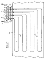
- Distribution conduit 10 provides the supply of water to pipe network 3, as shown in figure 2 .
- the inlet distribution pipe 10 is for instance provided with three connecting points 9 to which a pipe end 12 of the pipe network is connected in each case.
- FIG. 2 A typical pattern of the pipe network is shown in figure 2 .
- the water supplied to the pipe network must then be drained again by means of an outlet distribution pipe 11.
- This distribution pipe is likewise provided with three connecting points 9' to which the outer ends 12' of pipe 3 are connected.
- FIG. 3 shows a perspective view of an embodiment of the device according to the invention.
- the assembly consists of a container 1 and a cover 13.
- Distribution opening 16 is suitable for receiving a pipe end of the distribution pipe, while distribution opening 16' is suitable for receiving the socket end of the distribution pipe.
- This embodiment is particularly convenient when different containers must be coupled to each other, since a socket end 16' can be coupled in simple manner to a pipe end of a distribution pipe.
- Container 1 is provided along both sides on its upper edge with a substantially horizontal flange 17 in which semicircular channels 18 are arranged.
- Cover 13 takes a profiled form and the middle part 20 thereof is given an elevated form to provide sufficient space for connecting pipe ends 12, 12' to distribution pipe 10, 11.
- the distribution openings 16, 16' arranged in the upright side walls 15 of container 1 are shown in detail in figure 6 .
- Figure 4 shows a top view of an embodiment of the device according to the invention in which the inlet and outlet distribution pipes 10 and 11 are arranged.
- the socket end 24 of inlet distribution pipe 10 is connected to distribution opening 16, while the pipe end of inlet distribution pipe 10 protrudes from the distribution opening 16.
- the distribution outlet pipe 11 is placed in similar manner in container 1, although in reverse direction.
- FIG 5 clearly shows the semicircular shape of semicircular channels 18 arranged in the flange on the upper edge of container 1.
- two spacers 21 are arranged between two upright walls 15. These support elements prevent a deformation of the walls when container 1 is placed in the ground, so that cover 13 can be placed without problems in container 1.
- Figures 7 and 8 respectively show a top and side view of an embodiment of cover 13.
- eight semicircular channels 19 are arranged in the lower edge of cover 13.
- the radius of the semicircular channels 18 and 19 is preferably larger than the radius of jacket 2, so that during fitting of a pipe of the pipe network there is sufficient clearance to realize the connection to the distribution pipe.
- Cover 13 is mounted on container 1 via screws through holes 28 in the cover.
- a distribution box consisting for instance of three assemblies of container 1 and cover 13
- one outer end of the assembly of the three mutually coupled distribution pipes 10, 11 will have to be connected in each case to a main pipe, and the other outer end will have to be closed.
- Closing can for instance take place using the stopper 26 shown figure 9 .
- Such a stopper 26 can be fixed with tensile strength to the side wall using bolts, for instance by means of press-in nuts.
- Supply to the distribution pipe can for instance take place by means of a pipe bend 27 with a socket 29 with flange on one side and a pipe on the other side, as shown in figure 10 .
- the socket end 29 is pushed over the pipe ends of distribution pipe 10, 11 and fixed with bolts to the side of container 1.
- the pipe end of pipe bend 27 can be connected to the main pipe, for instance by means of a tensively strong socket.
- Mutual coupling of a number of containers 1 can take place by placing pipe ends 25 into sockets 24 and mutually connecting containers 1 by means of a stainless bolt.
- the embodiment variant of the device according to the invention shown in figure 4 can be manufactured from polyethylene by rotation moulding and weighs, for instance with distribution pipes, about 32 kg with cover and about 25 kg without cover.
- This light embodiment has the advantage that one man can construct the distribution station easily and quickly. Despite the light weight, this embodiment variant can still effectively withstand a high earth pressure, among other reasons because of the additional pressure-absorbing beams 30 welded on the inside of the container.
- the connecting points on distribution pipe 9, 9' are preferably provided with a tap, which can be closed if the connecting point is not in use.
- the distribution openings in the side wall of the container can be filled with polyethylene plugs.
Landscapes
- Engineering & Computer Science (AREA)
- General Engineering & Computer Science (AREA)
- Chemical & Material Sciences (AREA)
- Thermal Sciences (AREA)
- Combustion & Propulsion (AREA)
- Mechanical Engineering (AREA)
- Physics & Mathematics (AREA)
- Architecture (AREA)
- Civil Engineering (AREA)
- Structural Engineering (AREA)
- Laying Of Electric Cables Or Lines Outside (AREA)
- Refuge Islands, Traffic Blockers, Or Guard Fence (AREA)
- Supports For Pipes And Cables (AREA)
- Road Signs Or Road Markings (AREA)
Claims (13)
- Vorrichtung zum Verbinden eines Rohrnetzes (3) mit einer Verteilerleitung (10, 11), mit einer Baugruppe bestehend aus einem Behälter (1) mit aufrechten Wänden (15) und einer daran angebrachten Abdeckung (13), die mit zumindest zwei Öffnungen (14) versehen ist, durch die jeweils ein äußeres Ende (12) eines Rohres (3) des Rohrnetzes zugeführt werden kann, um dieses äußere Ende (12) mit einem Verteilerrohr (10) zu verbinden, das in dem Behälter aufgenommen werden kann, wobei für jedes Verteilerrohr (10) zumindest eine Verteileröffnung (16) in der Baugruppe angeordnet ist, die mit dem äußeren Ende des Verteilerrohres (10) verbunden werden kann, dadurch gekennzeichnet, dass Aussparungen (14) an der Position der Verbindung zwischen den aufrechten Wänden (15) und der Abdeckung (13) angeordnet sind.
- Vorrichtung gemäß Anspruch 1, dadurch gekennzeichnet, dass in der Baugruppe zumindest zwei Verteileröffnungen (16) angeordnet sind, die mit einem äußeren Ende eines Verteilereinlassrohres (10) bzw. einem äußeren Ende eines Verteilerauslassrohres (11) verbunden werden können.
- Vorrichtung gemäß einem der vorangehenden Ansprüche, dadurch gekennzeichnet, dass für jedes Verteilerrohr zwei Verteileröffnungen (16, 16') in zwei gegenüberliegenden Wänden des Behälters angeordnet sind, wobei die Öffnungen mit beiden äußeren Enden eines Verteilerrohres (10) verbunden werden können.
- Vorrichtung gemäß einem der vorangehenden Ansprüche, dadurch gekennzeichnet, dass der Behälter (1) und die Abdeckung (13) aus steifem Kunststoff hergestellt sind.
- Vorrichtung gemäß einem der vorangehenden Ansprüche, dadurch gekennzeichnet, dass zumindest eine aufrechte Wand an seiner oberen Kante mit einem im Wesentlichen horizontalen Flansch (17) versehen ist, in dem halbrunde Kanäle (18) angeordnet sind, wobei die Kanäle mit halbrunden Kanälen (19) zueammenwirken, die in der unteren Kante der Abdeckung (13) angeordnet sind, um eine kanalförmige Aussparung zu bilden.
- Vorrichtung gemäß Anspruch 5, dadurch gekennzeichnet, dass die kanalförmige Aussparung einen Querschnitt aufweist, der größer ist als jener einer Ummantelung (2), durch die das äußere Ende eines Rohres des Rohrnetzes zugeführt werden kann.
- Vorrichtung gemäß einem der vorangehenden Ansprüche, dadurch gekennzeichnet, dass der mittlere Teil (20) der Abdeckung (13) eine erhabene Form hat.
- Vorrichtung gemäß einem der vorangehenden Ansprüche, dadurch gekennzeichnet, dass Abstandsstücke (21) zwischen zwei gegenüberliegenden aufrechten Wänden (15) des Behälters angeordnet sind, um die beiden gegenüberliegenden aufrechten Wände (15) in einem konstanten Abstand zu halten.
- Verfahren zum Verbinden eines Rohrnetzes (3), das sich in einer Fahrbahn (5) befindet, mit einer Verteilerleitung (10, 11), wobei- ein Behälter (1) in den Boden angrenzend an der Fahrbahn platziert wird;- ein oder mehrere Verteilerrohre (10, 11) der Verteilerleitung in den Behälter (1) platziert und mit entsprechenden Verteileröffnungen (16, 16') verbunden werden, die in dem Behälter (1) angeordnet sind, dadurch gekennzeichnet, dass- ein Rohrende (12, 12') von jedem Rohr des Rohrnetzes zum Verbinden entlang Aussparungen (18) geführt wird, die in der oberen Kante des Behälters angeordnet sind;- wobei die äußeren Enden (12, 12') dann auf Größe gebracht werden;- und dann über eine geeignete Kopplung (22) mit dem entsprechenden Verteilerrohr (10, 11) verbunden werden;- wonach der Behälter (1) durch eine Abdeckung (13) geschlossen wird.
- Verfahren gemäß Anspruch 9, dadurch gekennzeichnet, dass eine Ummantelung (2) in den Boden zwischen der Fahrbahn und dem Behälter (1) zum Führen eines Rohres (3) des Rohrnetzes angeordnet wird, wobei die Ummantelung (2) so ausgewählt wird, dass sie durch die Aussparungen zwischen der oberen Kante des Behälters (1) und der Abdeckung (13) passt.
- Verfahren gemäß Anspruch 9 oder 10, dadurch gekennzeichnet, dass eine Anzahl Behälter (1) gemäß der Anzahl Rohrenden zum Verbinden ausgewählt wird, wobei eine aufrechte Wand (15) eines ersten Behälters (1), die mit einer oder mehreren Verteileröffnungen (16, 16') versehen ist, gegenüber einer aufrechten Wand eines nachfolgend ausgewählten Behälters (1) platziert wird, der mit einer oder mehreren Verteileröffnungen (16', 16) versehen ist, und die entsprechende eine oder die entsprechenden mehreren Verteileröffnungen (16, 16') aneinander gekoppelt werden, wobei die Schritte wiederholt werden, bis alle ausgewählten Behälter (1) aneinander gekoppelt sind.
- Verfahren gemäß Anspruch 11, dadurch gekennzeichnet, dass eine geeignete Anzahl Verteilerrohre (10, 11) an deren äußeren Ende mit einer Fassung derart versehen ist, dass ein Fassungsende (24) eines Verteilerrohres gegenüber einem Rohrende (25) des Verteilerrohres (10, 11) liegt, um es daran zu koppeln, und dass die entsprechenden Verteilerrohre (10, 11) aneinander gekoppelt werden, indem das Fassungsende (24) über das Rohrende (25) geschoben wird.
- Verfahren gemäß einem der Ansprüche 9 bis 12, dadurch gekennzeichnet, dass ein äußeres Ende des Verteilerrohres (10, 11) oder der Baugruppe der aneinander gekoppelten Verteilerrohre (10, 11) mit einem Hauptrohr über ein geeignetes Verbindungsstück (27) verbunden wird, und dass das andere Ende unter Verwendung eines Stoppers (26) geschlossen wird.
Applications Claiming Priority (2)
| Application Number | Priority Date | Filing Date | Title |
|---|---|---|---|
| NL1022113A NL1022113C2 (nl) | 2002-12-09 | 2002-12-09 | Inrichting voor het aansluiten van een in een rijweg gelegen buizennetwerk, en een werkwijze voor het gebruik van deze inrichting. |
| NL1022113 | 2002-12-09 |
Publications (2)
| Publication Number | Publication Date |
|---|---|
| EP1428934A1 EP1428934A1 (de) | 2004-06-16 |
| EP1428934B1 true EP1428934B1 (de) | 2008-07-30 |
Family
ID=32322556
Family Applications (1)
| Application Number | Title | Priority Date | Filing Date |
|---|---|---|---|
| EP03078875A Expired - Lifetime EP1428934B1 (de) | 2002-12-09 | 2003-12-08 | Vorrichtung zum Verbinden eines Rohrnetzes in einer Fahrbahn und Anwendungsverfahren |
Country Status (4)
| Country | Link |
|---|---|
| EP (1) | EP1428934B1 (de) |
| AT (1) | ATE403036T1 (de) |
| DE (1) | DE60322497D1 (de) |
| NL (1) | NL1022113C2 (de) |
Families Citing this family (3)
| Publication number | Priority date | Publication date | Assignee | Title |
|---|---|---|---|---|
| RU2287040C2 (ru) * | 2004-10-15 | 2006-11-10 | Эрнст Михайлович Симкин | Устройство для обогрева или охлаждения дорожного покрытия |
| NL2000534C2 (nl) | 2007-03-13 | 2008-09-16 | H A Prince Beheer Bergen Op Zoom Bv | Inrichting voor het aansluiten van een buizennetwerk. |
| US8342211B2 (en) | 2010-06-25 | 2013-01-01 | Fenix Energy Solutions Ltd. | Protective pipe cover and support apparatus |
Family Cites Families (2)
| Publication number | Priority date | Publication date | Assignee | Title |
|---|---|---|---|---|
| US2570226A (en) * | 1947-10-30 | 1951-10-09 | Geiringer Paul Ludwig | Airport heating and airport fog dispersal |
| US3568924A (en) * | 1969-06-25 | 1971-03-09 | Lawrence H Chenault | Snow melting system |
-
2002
- 2002-12-09 NL NL1022113A patent/NL1022113C2/nl not_active IP Right Cessation
-
2003
- 2003-12-08 AT AT03078875T patent/ATE403036T1/de active
- 2003-12-08 EP EP03078875A patent/EP1428934B1/de not_active Expired - Lifetime
- 2003-12-08 DE DE60322497T patent/DE60322497D1/de not_active Expired - Lifetime
Also Published As
| Publication number | Publication date |
|---|---|
| ATE403036T1 (de) | 2008-08-15 |
| DE60322497D1 (de) | 2008-09-11 |
| NL1022113C2 (nl) | 2004-06-18 |
| EP1428934A1 (de) | 2004-06-16 |
Similar Documents
| Publication | Publication Date | Title |
|---|---|---|
| JP3436916B2 (ja) | 鉄製マンホール | |
| US8001643B1 (en) | Cable protector | |
| EP3540331B1 (de) | An eine erdwärmequelle anschliessbare geothermieanlage | |
| US20130055650A1 (en) | Modular Integrated Underground Utilities Enclosure and Distribution System | |
| EP1428934A1 (de) | Vorrichtung zum Verbinden eines Rohrnetzes in einer Fahrbahn und Anwendungsverfahren | |
| US20040120762A1 (en) | Adjustable utility access | |
| WO2001024336A1 (en) | An underwater cable protection pipe | |
| EP0707121B1 (de) | Panelen für die Herstellung oberirdischer Rundbehälter, Giessform und Verfahren zu ihrer Herstellung | |
| EP2850263B1 (de) | Installationskabine | |
| EP0219262B1 (de) | Gebäude für rauhe Umgebungsbedingungen | |
| KR20130015697A (ko) | 조립식주택 | |
| JP2000291038A (ja) | ハンドホール | |
| JP2023064827A (ja) | 緊急施設の設置方法およびタイヤ治具 | |
| NO347226B1 (no) | Bæreelement for en søyle for et elektrisk utstyr, et system, og en framgangsmåte ved bruk av samme | |
| WO2015042227A1 (en) | A terrain compliant, eco-friendly, modular ballast system with optional integrated wire management and racking system | |
| CN212317644U (zh) | 一种市政道路基坑安全防护装置 | |
| US20250084606A1 (en) | Underground utility enclosure system and method | |
| KR20010080891A (ko) | 배수파이프용 권곡벽 | |
| KR102914413B1 (ko) | 맨홀 뚜껑 개폐장치 | |
| CN223458850U (zh) | 一种适用于高速铁路控制点保护井预制装置 | |
| KR20030026173A (ko) | Frp 박스암거의 시공방법 및 구조 | |
| AU2008203248A1 (en) | Fluid reservoir | |
| JP2003274546A (ja) | コンクリート製ボックスの組み立て方法およびプレハブユニット | |
| WO1997013686A1 (en) | Supply culvert at parking sites for airplanes at airports | |
| US6464022B1 (en) | Mobile horizontal directional boring apparatus and method for use in boring from existing utility manholes |
Legal Events
| Date | Code | Title | Description |
|---|---|---|---|
| PUAI | Public reference made under article 153(3) epc to a published international application that has entered the european phase |
Free format text: ORIGINAL CODE: 0009012 |
|
| AK | Designated contracting states |
Kind code of ref document: A1 Designated state(s): AT BE BG CH CY CZ DE DK EE ES FI FR GB GR HU IE IT LI LU MC NL PT RO SE SI SK TR |
|
| AX | Request for extension of the european patent |
Extension state: AL LT LV MK |
|
| 17P | Request for examination filed |
Effective date: 20041208 |
|
| AKX | Designation fees paid |
Designated state(s): AT BE BG CH CY CZ DE DK EE ES FI FR GB GR HU IE IT LI LU MC NL PT RO SE SI SK TR |
|
| GRAP | Despatch of communication of intention to grant a patent |
Free format text: ORIGINAL CODE: EPIDOSNIGR1 |
|
| GRAS | Grant fee paid |
Free format text: ORIGINAL CODE: EPIDOSNIGR3 |
|
| GRAA | (expected) grant |
Free format text: ORIGINAL CODE: 0009210 |
|
| AK | Designated contracting states |
Kind code of ref document: B1 Designated state(s): AT BE BG CH CY CZ DE DK EE ES FI FR GB GR HU IE IT LI LU MC NL PT RO SE SI SK TR |
|
| REG | Reference to a national code |
Ref country code: GB Ref legal event code: FG4D |
|
| REG | Reference to a national code |
Ref country code: CH Ref legal event code: NV Representative=s name: ARNOLD & SIEDSMA AG Ref country code: CH Ref legal event code: EP |
|
| REF | Corresponds to: |
Ref document number: 60322497 Country of ref document: DE Date of ref document: 20080911 Kind code of ref document: P |
|
| REG | Reference to a national code |
Ref country code: IE Ref legal event code: FG4D |
|
| PG25 | Lapsed in a contracting state [announced via postgrant information from national office to epo] |
Ref country code: ES Free format text: LAPSE BECAUSE OF FAILURE TO SUBMIT A TRANSLATION OF THE DESCRIPTION OR TO PAY THE FEE WITHIN THE PRESCRIBED TIME-LIMIT Effective date: 20081110 Ref country code: PT Free format text: LAPSE BECAUSE OF FAILURE TO SUBMIT A TRANSLATION OF THE DESCRIPTION OR TO PAY THE FEE WITHIN THE PRESCRIBED TIME-LIMIT Effective date: 20081230 |
|
| PG25 | Lapsed in a contracting state [announced via postgrant information from national office to epo] |
Ref country code: SI Free format text: LAPSE BECAUSE OF FAILURE TO SUBMIT A TRANSLATION OF THE DESCRIPTION OR TO PAY THE FEE WITHIN THE PRESCRIBED TIME-LIMIT Effective date: 20080730 Ref country code: BG Free format text: LAPSE BECAUSE OF FAILURE TO SUBMIT A TRANSLATION OF THE DESCRIPTION OR TO PAY THE FEE WITHIN THE PRESCRIBED TIME-LIMIT Effective date: 20081030 Ref country code: FI Free format text: LAPSE BECAUSE OF FAILURE TO SUBMIT A TRANSLATION OF THE DESCRIPTION OR TO PAY THE FEE WITHIN THE PRESCRIBED TIME-LIMIT Effective date: 20080730 |
|
| PG25 | Lapsed in a contracting state [announced via postgrant information from national office to epo] |
Ref country code: EE Free format text: LAPSE BECAUSE OF FAILURE TO SUBMIT A TRANSLATION OF THE DESCRIPTION OR TO PAY THE FEE WITHIN THE PRESCRIBED TIME-LIMIT Effective date: 20080730 Ref country code: DK Free format text: LAPSE BECAUSE OF FAILURE TO SUBMIT A TRANSLATION OF THE DESCRIPTION OR TO PAY THE FEE WITHIN THE PRESCRIBED TIME-LIMIT Effective date: 20080730 |
|
| PG25 | Lapsed in a contracting state [announced via postgrant information from national office to epo] |
Ref country code: CZ Free format text: LAPSE BECAUSE OF FAILURE TO SUBMIT A TRANSLATION OF THE DESCRIPTION OR TO PAY THE FEE WITHIN THE PRESCRIBED TIME-LIMIT Effective date: 20080730 Ref country code: RO Free format text: LAPSE BECAUSE OF FAILURE TO SUBMIT A TRANSLATION OF THE DESCRIPTION OR TO PAY THE FEE WITHIN THE PRESCRIBED TIME-LIMIT Effective date: 20080730 Ref country code: SK Free format text: LAPSE BECAUSE OF FAILURE TO SUBMIT A TRANSLATION OF THE DESCRIPTION OR TO PAY THE FEE WITHIN THE PRESCRIBED TIME-LIMIT Effective date: 20080730 |
|
| PLBE | No opposition filed within time limit |
Free format text: ORIGINAL CODE: 0009261 |
|
| STAA | Information on the status of an ep patent application or granted ep patent |
Free format text: STATUS: NO OPPOSITION FILED WITHIN TIME LIMIT |
|
| 26N | No opposition filed |
Effective date: 20090506 |
|
| PG25 | Lapsed in a contracting state [announced via postgrant information from national office to epo] |
Ref country code: MC Free format text: LAPSE BECAUSE OF NON-PAYMENT OF DUE FEES Effective date: 20081231 |
|
| PG25 | Lapsed in a contracting state [announced via postgrant information from national office to epo] |
Ref country code: IT Free format text: LAPSE BECAUSE OF FAILURE TO SUBMIT A TRANSLATION OF THE DESCRIPTION OR TO PAY THE FEE WITHIN THE PRESCRIBED TIME-LIMIT Effective date: 20080730 |
|
| REG | Reference to a national code |
Ref country code: IE Ref legal event code: MM4A |
|
| REG | Reference to a national code |
Ref country code: FR Ref legal event code: ST Effective date: 20090831 |
|
| PG25 | Lapsed in a contracting state [announced via postgrant information from national office to epo] |
Ref country code: IE Free format text: LAPSE BECAUSE OF NON-PAYMENT OF DUE FEES Effective date: 20081208 |
|
| PG25 | Lapsed in a contracting state [announced via postgrant information from national office to epo] |
Ref country code: SE Free format text: LAPSE BECAUSE OF FAILURE TO SUBMIT A TRANSLATION OF THE DESCRIPTION OR TO PAY THE FEE WITHIN THE PRESCRIBED TIME-LIMIT Effective date: 20081030 |
|
| PG25 | Lapsed in a contracting state [announced via postgrant information from national office to epo] |
Ref country code: FR Free format text: LAPSE BECAUSE OF NON-PAYMENT OF DUE FEES Effective date: 20081231 |
|
| PG25 | Lapsed in a contracting state [announced via postgrant information from national office to epo] |
Ref country code: LU Free format text: LAPSE BECAUSE OF NON-PAYMENT OF DUE FEES Effective date: 20081208 Ref country code: HU Free format text: LAPSE BECAUSE OF FAILURE TO SUBMIT A TRANSLATION OF THE DESCRIPTION OR TO PAY THE FEE WITHIN THE PRESCRIBED TIME-LIMIT Effective date: 20090131 Ref country code: CY Free format text: LAPSE BECAUSE OF FAILURE TO SUBMIT A TRANSLATION OF THE DESCRIPTION OR TO PAY THE FEE WITHIN THE PRESCRIBED TIME-LIMIT Effective date: 20080730 |
|
| PG25 | Lapsed in a contracting state [announced via postgrant information from national office to epo] |
Ref country code: TR Free format text: LAPSE BECAUSE OF FAILURE TO SUBMIT A TRANSLATION OF THE DESCRIPTION OR TO PAY THE FEE WITHIN THE PRESCRIBED TIME-LIMIT Effective date: 20080730 |
|
| PG25 | Lapsed in a contracting state [announced via postgrant information from national office to epo] |
Ref country code: GR Free format text: LAPSE BECAUSE OF FAILURE TO SUBMIT A TRANSLATION OF THE DESCRIPTION OR TO PAY THE FEE WITHIN THE PRESCRIBED TIME-LIMIT Effective date: 20081031 |
|
| REG | Reference to a national code |
Ref country code: NL Ref legal event code: UD Effective date: 20130214 |
|
| REG | Reference to a national code |
Ref country code: NL Ref legal event code: PLED Effective date: 20130423 |
|
| REG | Reference to a national code |
Ref country code: NL Ref legal event code: UD Effective date: 20140102 |
|
| PGFP | Annual fee paid to national office [announced via postgrant information from national office to epo] |
Ref country code: CH Payment date: 20150327 Year of fee payment: 12 |
|
| PGFP | Annual fee paid to national office [announced via postgrant information from national office to epo] |
Ref country code: GB Payment date: 20150325 Year of fee payment: 12 Ref country code: AT Payment date: 20150327 Year of fee payment: 12 |
|
| PG25 | Lapsed in a contracting state [announced via postgrant information from national office to epo] |
Ref country code: BE Free format text: LAPSE BECAUSE OF NON-PAYMENT OF DUE FEES Effective date: 20141231 |
|
| PGFP | Annual fee paid to national office [announced via postgrant information from national office to epo] |
Ref country code: NL Payment date: 20150331 Year of fee payment: 12 |
|
| PGFP | Annual fee paid to national office [announced via postgrant information from national office to epo] |
Ref country code: DE Payment date: 20150331 Year of fee payment: 12 |
|
| PGFP | Annual fee paid to national office [announced via postgrant information from national office to epo] |
Ref country code: BE Payment date: 20150401 Year of fee payment: 12 |
|
| PGRI | Patent reinstated in contracting state [announced from national office to epo] |
Ref country code: BE Effective date: 20150613 |
|
| PG25 | Lapsed in a contracting state [announced via postgrant information from national office to epo] |
Ref country code: BE Free format text: LAPSE BECAUSE OF NON-PAYMENT OF DUE FEES Effective date: 20151231 |
|
| REG | Reference to a national code |
Ref country code: DE Ref legal event code: R119 Ref document number: 60322497 Country of ref document: DE |
|
| REG | Reference to a national code |
Ref country code: CH Ref legal event code: PL |
|
| REG | Reference to a national code |
Ref country code: AT Ref legal event code: MM01 Ref document number: 403036 Country of ref document: AT Kind code of ref document: T Effective date: 20151208 |
|
| GBPC | Gb: european patent ceased through non-payment of renewal fee |
Effective date: 20151208 |
|
| REG | Reference to a national code |
Ref country code: NL Ref legal event code: MM Effective date: 20160101 |
|
| PG25 | Lapsed in a contracting state [announced via postgrant information from national office to epo] |
Ref country code: DE Free format text: LAPSE BECAUSE OF NON-PAYMENT OF DUE FEES Effective date: 20160701 Ref country code: LI Free format text: LAPSE BECAUSE OF NON-PAYMENT OF DUE FEES Effective date: 20151231 Ref country code: NL Free format text: LAPSE BECAUSE OF NON-PAYMENT OF DUE FEES Effective date: 20160101 Ref country code: CH Free format text: LAPSE BECAUSE OF NON-PAYMENT OF DUE FEES Effective date: 20151231 Ref country code: GB Free format text: LAPSE BECAUSE OF NON-PAYMENT OF DUE FEES Effective date: 20151208 |
|
| PG25 | Lapsed in a contracting state [announced via postgrant information from national office to epo] |
Ref country code: AT Free format text: LAPSE BECAUSE OF NON-PAYMENT OF DUE FEES Effective date: 20151208 |