EP0219262B1 - Gebäude für rauhe Umgebungsbedingungen - Google Patents
Gebäude für rauhe Umgebungsbedingungen Download PDFInfo
- Publication number
- EP0219262B1 EP0219262B1 EP19860307502 EP86307502A EP0219262B1 EP 0219262 B1 EP0219262 B1 EP 0219262B1 EP 19860307502 EP19860307502 EP 19860307502 EP 86307502 A EP86307502 A EP 86307502A EP 0219262 B1 EP0219262 B1 EP 0219262B1
- Authority
- EP
- European Patent Office
- Prior art keywords
- building
- base perimeter
- exterior
- wall
- exterior surface
- Prior art date
- Legal status (The legal status is an assumption and is not a legal conclusion. Google has not performed a legal analysis and makes no representation as to the accuracy of the status listed.)
- Expired
Links
- 239000000463 material Substances 0.000 claims description 3
- 239000002990 reinforced plastic Substances 0.000 claims 1
- 230000007613 environmental effect Effects 0.000 description 3
- 230000004048 modification Effects 0.000 description 2
- 238000012986 modification Methods 0.000 description 2
- 230000004308 accommodation Effects 0.000 description 1
- 230000004075 alteration Effects 0.000 description 1
- NEHMKBQYUWJMIP-UHFFFAOYSA-N chloromethane Chemical compound ClC NEHMKBQYUWJMIP-UHFFFAOYSA-N 0.000 description 1
- 239000011248 coating agent Substances 0.000 description 1
- 238000000576 coating method Methods 0.000 description 1
- 238000010276 construction Methods 0.000 description 1
- 239000011152 fibreglass Substances 0.000 description 1
- 238000000465 moulding Methods 0.000 description 1
- 239000004033 plastic Substances 0.000 description 1
- 229920003023 plastic Polymers 0.000 description 1
- 239000000088 plastic resin Substances 0.000 description 1
- 230000000717 retained effect Effects 0.000 description 1
- 238000009991 scouring Methods 0.000 description 1
Images

Classifications
-
- E—FIXED CONSTRUCTIONS
- E04—BUILDING
- E04H—BUILDINGS OR LIKE STRUCTURES FOR PARTICULAR PURPOSES; SWIMMING OR SPLASH BATHS OR POOLS; MASTS; FENCING; TENTS OR CANOPIES, IN GENERAL
- E04H9/00—Buildings, groups of buildings or shelters adapted to withstand or provide protection against abnormal external influences, e.g. war-like action, earthquake or extreme climate
- E04H9/16—Buildings, groups of buildings or shelters adapted to withstand or provide protection against abnormal external influences, e.g. war-like action, earthquake or extreme climate against adverse conditions, e.g. extreme climate, pests
Definitions
- This invention relates generally to a land building for harsh environments, and in particular to such a building including: one or more rigid exterior walls extending upwardly from a base perimeter of the building, in building use the base perimeter being adjacent a surface surrounding the building and on which the building is supported, the exterior wall(s) providing an exterior surface of the building that curves outwardly and upwardly from the base perimeter, whereby the exterior wall(s) have an undercut region adjacent the base perimeter.
- the present invention is applicable as a portable building used in snow fields, including the arctic and antarctic regions, for accommodation and work shelter and it will be convenient to hereinafter disclose the invention in relation to that exemplary application. It is to be appreciated, however, that the invention is not limited to that application.
- the present invention provides in one broad aspect a building as sat forth above and characterised in that the exterior surface in the undercut region has a radius of curvature equal to about half the width of the building, the width of the building being at a level above the base perimeter at which upward extent of the undercut region terminates, and the upward extent of the building undercut region above the base perimeter being about one-fifth the building width and/or about two-sevenths of the total building height above the base perimeter.
- the exterior surface preferably curves at least substantially throughout the upward extent of the exterior wall(s) from the base perimeter. Whilst that curvature is outward and upward in the undercut region, the surface will preferably thereafter curve inwardly and upwardly. Thus, preferably the exterior surface will have a bulged shape over its upward extent.
- the exterior wall(s) preferably extend upwardly toward a top of the building and inwardly toward one another. In that regard, preferably the wall(s) terminate adjacent one another so as to provide at least substantially the entire external surface of the building.
- the building base perimeter is preferably curved along at least a partial extent thereof.
- the building is portable in the sense that it can be transported between use and storage sites. That transportation can preferably be achieved with the building erected ready for use. However, additionally the building can preferably be selectively disassembled for transportation and storage, and assembled and reassembled as desired for use. To that end, at least some of the building wall(s) are preferably constructed of wall panels arranged to be interconnected for assembly of the building and disconnected for dismantling that building.
- a building kit of the above building is provided.
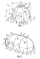
- Fig. 1 is a perspective view of the building according to one preferred embodiment of the present invention.
- Fig. 2 is a perspective view of the building according to another preferred embodiment of the present invention.
- Fig. 3 is an exploded perspective view of part of the building of Fig. 2;
- Fig. 4 is a side elevation of a pair of the buildings of Fig. 1 interconnected so as to provide a building complex.
- FIGs. 1 to 3 there is illustrated two different, but nevertheless generally similar buildings 1, erected on ground B.
- Building 1 has one (as illustrated in Fig. 1) or more (as illustrated in Figs. 2 or 3) exterior building walls 2, extending upwardly from base perimeter 3, and providing exterior surface 4, exposed to the surrounding environment.
- Exterior surface 4 curves upwardly from base perimeter 3, in such a manner that surface 4, is slightly bulged.
- Median horizontal plane P passes through building 1, at its widest extent with surface 4, extending outwardly and upwardly from base perimeter 3, to plane P, so as to form undercut region 5, in walls 2. Above median plane P, surface 4, extends generally inwardly and upwardly.
- Wall(s) 2 provide exterior surfacd 4, with a curvature related to the overall width of building 1, at least in undercut region 5.
- the curvature has radius R, which is equal to about half width W, of building 1, at plane P.
- Upward extent h, of building 1, in undercut region 5, is a small proportion of width W, and/or height H, of building 1.
- upward extent h will generally be about one fifth building width W.
- extent h may be about two sevenths of total building height H, where a greater upward extent h, is provided.
- building width W will be at plane P, whilst building height H, will be the maximum vertical distance from perimeter 3.
- Exterior surface 4 may conveniently have the same radius of curvature R, throughout its upward extent, i.e., the same radius R, as in undercut region 5. However, curvatures of different radii are evisaged.
- exterior surface 4 may curve upwardly and converge toward one another at building top 6, so that wall(s) 2, generally provide both the side and top or roof of building l. Thus, there need be no separate side and top walls in building l.
- exterior surface 4 may meet an exterior surface of one or more separate top walls connected to wall(s) 2, which become side walls. Where that occurs, then exterior surface 4, of wall(s) 2, will generally merge smoothly with the top wall exterior surface.
- the upward curvature of exterior surface 4 may or may not continue through the top wall exterior surface so that, for example, the top wall exterior surface may be differently curved or may be generally planar.
- Building l may have any suitable plan shape.
- building l may have a single wall 2, and so be generally circular in plan shape, as illustrated in Fig. l.
- building l may have multiple walls 2, with those walls 2, being straight and/or curved in plan and so be generally oblong (as illustrated in Figs. 2 and 3), oval, or square-shaped (for example).
- Building wall(s) 2 are constructed of wall panels 7, each arranged side-by-side one another along base perimeter 3. Where base perimeter 3, is curved then wall panels 7, will be generally segmental shaped (as illustrated) so as to fit one next to another. Any top wall(s) (not illustrated) or cap Pieces 8, may be provided as necessary to "fill in” between panels 7, at top 6.
- Each panel 7, has outer shell 9, with spaced side edge portions l0. Opposing side edge portions l0, of adjacent panels 7, are in juxtaposition, with adjacent wall panels 7, being interconnected at juxtaposed edge portions 9, to achieve building assembly. That may be achieved by providing each edge portion 9, with connecting flange ll, juxtaposed flanges ll, in turn being fastened together with suitable fastening elements (not illustrated) for example, bolts extending through aligned apertures in flanges ll. Flanges ll, may extend inwardly (as illustrated) or outwardly (not illustrated) relative to exterior surface 4. As will be well appreciated by those skilled in the art, shells 9, will be interconnected so as to form weatherproof seals between panels 7.
- Wall(s) 2, and any top wall(s) may be composed of any suitable material.
- wall(s) 2, and in particular panel shells 9, may be molded from plastics material such as plastic resin reinforced with fibreglass. Building features may be incorporated into panel shells 9, during and/or following molding. Exterior surfaces 4, (and also the interior surface of panels 7) may be treated as desired so that, for example, the interior surface may be provided with a decorative and/or heat insulating coating.
- building l may also include a base wall providing base perimeter 3, from which wall(s) 2, upstand, and that base wall may form a floor of building l.
- That base wall may be constructed of one or more wall sections or panels to facilitate building assembly and disassembly as outlined above.
- that base wall may be interconnected to wall(s) 2, for building assembly and disconnected therefrom for building disassembly. That connection may be achieved by providing end edge portions l4, wall panels 7, with connecting flanges l5, abutting the base wall at base perimeter 3, flanges l5, and the base wall being fastened together through suitable fastening elements (not illustrated) for example, bolts extending through aligned apertures therein.
- connection elements l6, to which tie lines T, can be attached. Those tie lines T, will in turn be secured to ground G, and drawn taut so as to firmly hold building l, against ground G.
- Connection elements l6, may be spaced apart about exterior surface 4, at plane P. Connection elements l6, may be connection lugs projecting outwardly from exterior surface 4.
- Connection elements l6, may also facilitate transportation of building l.
- connection elements l6, may be used to secure building l, to a transporter, whether aircraft, landcraft, or watercraft.
- snow blown about building l tends to be dispersed away rather than collect about base perimeter 3. That occurs, at least to some extent, by the action of wind about building undercut region 5, scouring snow from adjacent base perimeter 3, and carrying it away from building l. As such, access to and from building l, can be retained, and building damage or collapse avoided, during these environmental conditions.
- FIG. 4 there is shown a modification of building l, of Fig. l whereby two buildings l, are arranged close to one another and interconnected through corridor panels l7, providing an internal corridor interconnecting the interior of buildings l, and thereby forming a building complete.
- Corridor panels l7 may interconnect oppositely facing doorways or other openings provided in individual wall panels 7.
- Panels l7 may be removably connected to or formed integral with those respective panels 7. Any number of panels l7, may be used to provide the corridor, and those panels l7, may be constructed and interconnected together in a similar manner to panels 7. It should be well appreciated that additional buildings l, may be added to the complex, and interconnected in any desired arrangement by suitably shaped corridor panels l7, or other connecting facilities.
- the building of the present invention may be of a simple and rugged construction able to withstand physically harsh external conditions, cindlugin environmental conditions. Moreover, the building can be constructed for rapid assembly and disassembly as desired, the building being transportable in either an assembled or disassembled condition. These features make the building particularly suitable for temporary or permanent use in harsh external conditions where building transportation and setting up and ongoing building existence may otherwise be difficult and uncertain.
- the building is constructed for assembly and disassembly as desired, that can be achieved easily with little expertise or building tools. Disassembly of the building may also facilitate transportation and storage.
Landscapes
- Engineering & Computer Science (AREA)
- Architecture (AREA)
- Life Sciences & Earth Sciences (AREA)
- Pest Control & Pesticides (AREA)
- Business, Economics & Management (AREA)
- Emergency Management (AREA)
- Environmental & Geological Engineering (AREA)
- Civil Engineering (AREA)
- Structural Engineering (AREA)
- Finishing Walls (AREA)
Claims (11)
- Gebäude zur Verwendung in rauhen Umgebungen, mit einer oder mehreren starren Aussenwänden (2), welche sich von einem Basisumfang (3) des Gebäudes (1) nach oben erstrecken, wobei bei Verwendung des Gebäudes der Basisumfang (3) sich neben einer Gebäude (1) umgebenden und dieses tragenden Oberfläche (G), befindet, wobei die Aussenwand (-wände) (2) eine Aussenfläche (4) des Gebäudes (1) bildet (bilden), welche sich vom Basisumfang (3) nach aussen und nach oben krümmt, wodurch die Aussenwand (wände) (2) einen hinterschnittenen Bereich (5) neben dem Basisumfang (3) hat (haben), dadurch gekennzeichnet, dass die Aussenfläche (4) im hinterschnittenen Bereich (5) einen Krümmungsradius (R) gleich etwa der halben Breite (W) des Gebäudes (1) hat, wobei die Breite (W) des Gebäudes (1) auf einer Höhe (L) über dem Basisumfang liegt, in welcher die nach oben gehende Ausdehnung des hinterschnittenen Bereiches (5) endet, und die nach oben gehende Ausdehnung des hinterschnittenen Bereiches (5) des Gebäudes über dem Basisumfang (3) etwa 1/5 der Gebäudebreite (W) und/oder etwa 2/7 der Gesamthöhe (H) des Gebäudes über dem Basisumfang (3) ist.
- Gebäude nach Anspruch 1, dadurch gekennzeichnet, dass die Aussenfläche (4) sich mindestens im wesentlichen über die gesamte nach oben gehende Ausdehnung der Aussenwand (-wände) (2) von Basisumfang (3) her krümmt, wobei die Aussenfläche (4) sich oberhalb des hinterschnittenen Bereiches (5) nach innen und nach oben krümmt, so dass die Aussenfläche (4) über ihrer gesamten Hochausdehnung eine im wesentlichen bauchige Form hat.
- Gebäude nach Anspruch 2, dadurch gekennzeichnet, dass die Aussenfläche (4) der Aussenwand (-wände) (2) mindestens im wesentlichen den gleichen Krümmungsradius (R) über der gesamten Hochausdehnung derselben hat (haben).
- Gebäude nach Anspruch 2 oder 3, dadurch gekennzeichnet, dass die Aussenwand (-wände) (2) gegeneinander nach innen oberhalb des Basisumfanges (3) konvergieren und bei- oder nebeneinander enden, um so mindestens im wesentlichen die gesamte Aussenfläche (4) des Gebäudes (1) zu bilden.
- Gebäude nach einem der vorangehenden Ansprüche, dadurch gekennzeichnet, dass der Basisumfang (3) entlang mindestens eines Teiles seiner Ausdehnung gekrümmt ist.
- Gebäude nach Anspruch 5, dadurch gekennzeichnet, dass der Basisumfang (3) mindestens im wesentlichen kreisförmig in einer Ebene ist.
- Gebäude nach einem der vorangehenden Ansprüche, dadurch gekennzeichnet, dass eine Vielzahl von Verbindungselementen (16) in Abstand voneinander um die Aussenfläche (4) verteilt sind, wobei Zugleinen (T) an den Verbindungselementen befestigt und an der Oberfläche (G) gesichert werden können, wobei die Zugleinen (T) festgezogen werden, um so das Gebäude (1) fest gegen die Oberfläche (G) festzuhalten.
- Gebäude nach Anspruch 7, dadurch gekennzeichnet, dass die Verbindungselemente (16) Verbindungsschleifen (16) sind, welche in einer Höhe (L) über dem Basisumfang (3), in welcher die Hochsausdehnung des unterschnittenen Bereiches (5) endet, angeordnet sind.
- Gebäude nach einem der vorangehenden Ansprüche, dadurch gekennzeichnet, dass die Aussenwand (-wände) (2) aus einer Reihe von Wandpanelen (7) mit voneinander getrennten Seitenrandbereichen (10) aufgebaut ist (sind), wobei die Wandpanele (7) nebeneinander entlang des Basisumfanges (3) angeordnet und an den nebeneinanderliegenden Seitenrandbereichen (10) untereinander verbunden sind, wobei die Wandpanele (7) zum Abbau des Gebäudes (1) voneinander trennbar sind.
- Gebäude nach Anspruch 9, dadurch gekennzeichnet, dass jedes Wandpanel (7) eine äussere Schale (9) hat, welche die Aussenfläche (4) bildet und die die Wandpanele (7) miteinander verbindenden Seitenrandbereiche (10) hat, wobei jede Schale (9) leichtgewichtig ist und aus einem verstärkten Kunststoffmaterial besteht.
- Gebäudebausatz des in Anspruch 9 oder 10 beanspruchten Gebäudes, dadurch gekennzeichnet, dass der Bausatz (1) die Reihe Aussenwandpanele (7) enthält, welche an nebeneinander geordneten Seitenrandbereichen (10) während des Aufbauens des Gebäudes (1) miteinander verbindbar sind.
Priority Applications (1)
| Application Number | Priority Date | Filing Date | Title |
|---|---|---|---|
| AT86307502T ATE62314T1 (de) | 1985-10-11 | 1986-10-01 | Gebaeude fuer rauhe umgebungsbedingungen. |
Applications Claiming Priority (3)
| Application Number | Priority Date | Filing Date | Title |
|---|---|---|---|
| AU2884/85 | 1985-10-11 | ||
| AUPH288485 | 1985-10-11 | ||
| AU63689/86A AU585075B2 (en) | 1985-10-11 | 1986-10-10 | Buildings for harsh environments |
Publications (3)
| Publication Number | Publication Date |
|---|---|
| EP0219262A2 EP0219262A2 (de) | 1987-04-22 |
| EP0219262A3 EP0219262A3 (en) | 1988-03-02 |
| EP0219262B1 true EP0219262B1 (de) | 1991-04-03 |
Family
ID=25634083
Family Applications (1)
| Application Number | Title | Priority Date | Filing Date |
|---|---|---|---|
| EP19860307502 Expired EP0219262B1 (de) | 1985-10-11 | 1986-10-01 | Gebäude für rauhe Umgebungsbedingungen |
Country Status (1)
| Country | Link |
|---|---|
| EP (1) | EP0219262B1 (de) |
Cited By (2)
| Publication number | Priority date | Publication date | Assignee | Title |
|---|---|---|---|---|
| DE19820232A1 (de) * | 1998-05-06 | 1999-11-11 | Laue Hans Joachim | Hütte, insbesondere Kälberhütte |
| DE10020530A1 (de) * | 2000-04-27 | 2001-11-29 | Tiedtke Hans Uwe | Notunterkunft, geschlossene Zelle, schwimmfähig, wärmeisoliert aus Hartschaumelementen |
Families Citing this family (5)
| Publication number | Priority date | Publication date | Assignee | Title |
|---|---|---|---|---|
| GB2199858B (en) * | 1987-01-17 | 1991-07-31 | Roger Beasley | Greenhouse construction |
| DE3924631C1 (de) * | 1989-07-26 | 1990-09-27 | Polarmar Gmbh, 2850 Bremerhaven, De | |
| GB2267916A (en) * | 1992-06-12 | 1993-12-22 | John Peter Green | Privacy module |
| DE10197004D2 (de) * | 2001-09-12 | 2004-07-22 | Hans-Uwe Tiedtke | Notunterkunft aus formgeschäumten Elementen |
| GB2382085A (en) * | 2001-11-16 | 2003-05-21 | Jeremy Michael Charlesworth | Portable circular building |
Family Cites Families (6)
| Publication number | Priority date | Publication date | Assignee | Title |
|---|---|---|---|---|
| GB517548A (en) * | 1938-07-29 | 1940-02-01 | Norman Stuart Bellman | Improvements in portable buildings |
| CH419564A (fr) * | 1965-07-22 | 1966-08-31 | Camoletti Bruno | Jeu d'éléments préfabriqués pour la construction d'un habitacle en forme d'ellipsoïde de révolution |
| CA1063310A (en) * | 1978-01-05 | 1979-10-02 | John R. Peirson | Building construction |
| FR2426122A1 (fr) * | 1978-05-16 | 1979-12-14 | Cotechnipp Sa | Batiment en forme de coupole et equipement propre a sa construction |
| GB2056518A (en) * | 1979-06-21 | 1981-03-18 | Plumley K | Frameless buildings |
| IT1218406B (it) * | 1980-04-21 | 1990-04-19 | Stoffelen Marcellus Franciscus | Pannello leggereo convesso autoportante per la composizione di cupole |
-
1986
- 1986-10-01 EP EP19860307502 patent/EP0219262B1/de not_active Expired
Cited By (4)
| Publication number | Priority date | Publication date | Assignee | Title |
|---|---|---|---|---|
| DE19820232A1 (de) * | 1998-05-06 | 1999-11-11 | Laue Hans Joachim | Hütte, insbesondere Kälberhütte |
| DE19820232B4 (de) * | 1998-05-06 | 2008-12-11 | Laue, Hans-Joachim, Prof. Dr. | Kälberhütte |
| DE10020530A1 (de) * | 2000-04-27 | 2001-11-29 | Tiedtke Hans Uwe | Notunterkunft, geschlossene Zelle, schwimmfähig, wärmeisoliert aus Hartschaumelementen |
| DE10020530C2 (de) * | 2000-04-27 | 2002-06-20 | Tiedtke Hans Uwe | Notunterkunft |
Also Published As
| Publication number | Publication date |
|---|---|
| EP0219262A2 (de) | 1987-04-22 |
| EP0219262A3 (en) | 1988-03-02 |
Similar Documents
| Publication | Publication Date | Title |
|---|---|---|
| US4848046A (en) | Buildings for harsh environments | |
| CA2238480C (en) | Wall structures for swimming pools | |
| US3791080A (en) | Floating or land based modular assembly for housing or commercial use | |
| US3665882A (en) | Buoyant structure | |
| US4655013A (en) | Prefabricated modular building and method of assembly | |
| US20040060245A1 (en) | Shelter construction kit | |
| FI3688240T3 (en) | Construction system for a building module | |
| US4106520A (en) | Enclosure | |
| US4567707A (en) | Geodesic structure | |
| EP0013285A1 (de) | Rahmenförmige Raumstruktur bestehend aus im wesentlichen Y-förmigen Elementen | |
| EP0170653B1 (de) | Kuppelbaustruktur | |
| EP4461905A1 (de) | Modulare, mobile, temporäre strukturen und herstellungsverfahren | |
| EP0219262B1 (de) | Gebäude für rauhe Umgebungsbedingungen | |
| US4698941A (en) | Framework for dome-shaped roofs | |
| US3898777A (en) | Dome and vault construction | |
| US4700514A (en) | Monocoque building shell | |
| US20030167702A1 (en) | Building structure | |
| US20150000216A1 (en) | Portable building structures | |
| US4611442A (en) | Large span dome | |
| CA2160771A1 (en) | Emergency shelter | |
| US3281998A (en) | Self-sustaining collapsible building structure | |
| US3062334A (en) | Metallic building structure | |
| GB2081768A (en) | Polyhedral building structure | |
| US3656267A (en) | Structures of two basic elements | |
| CA2225864C (en) | New age shelters |
Legal Events
| Date | Code | Title | Description |
|---|---|---|---|
| PUAI | Public reference made under article 153(3) epc to a published international application that has entered the european phase |
Free format text: ORIGINAL CODE: 0009012 |
|
| AK | Designated contracting states |
Kind code of ref document: A2 Designated state(s): AT BE CH DE ES FR GB GR IT LI LU NL SE |
|
| PUAL | Search report despatched |
Free format text: ORIGINAL CODE: 0009013 |
|
| AK | Designated contracting states |
Kind code of ref document: A3 Designated state(s): AT BE CH DE ES FR GB GR IT LI LU NL SE |
|
| 17P | Request for examination filed |
Effective date: 19880823 |
|
| 17Q | First examination report despatched |
Effective date: 19890717 |
|
| GRAA | (expected) grant |
Free format text: ORIGINAL CODE: 0009210 |
|
| AK | Designated contracting states |
Kind code of ref document: B1 Designated state(s): AT BE CH DE ES FR GB GR IT LI LU NL SE |
|
| PG25 | Lapsed in a contracting state [announced via postgrant information from national office to epo] |
Ref country code: IT Free format text: LAPSE BECAUSE OF FAILURE TO SUBMIT A TRANSLATION OF THE DESCRIPTION OR TO PAY THE FEE WITHIN THE PRE;WARNING: LAPSES OF ITALIAN PATENTS WITH EFFECTIVE DATE BEFORE 2007 MAY HAVE OCCURRED AT ANY TIME BEFORE 2007. THE CORRECT EFFECTIVE DATE MAY BE DIFFERENT FROM THE ONE RECORDED.SCRIBED TIME-LIMIT Effective date: 19910403 Ref country code: SE Effective date: 19910403 Ref country code: NL Effective date: 19910403 Ref country code: LI Effective date: 19910403 Ref country code: AT Effective date: 19910403 Ref country code: GR Free format text: LAPSE BECAUSE OF FAILURE TO SUBMIT A TRANSLATION OF THE DESCRIPTION OR TO PAY THE FEE WITHIN THE PRESCRIBED TIME-LIMIT Effective date: 19910403 Ref country code: FR Effective date: 19910403 Ref country code: CH Effective date: 19910403 Ref country code: BE Effective date: 19910403 |
|
| REF | Corresponds to: |
Ref document number: 62314 Country of ref document: AT Date of ref document: 19910415 Kind code of ref document: T |
|
| REF | Corresponds to: |
Ref document number: 3678522 Country of ref document: DE Date of ref document: 19910508 |
|
| PG25 | Lapsed in a contracting state [announced via postgrant information from national office to epo] |
Ref country code: ES Free format text: LAPSE BECAUSE OF FAILURE TO SUBMIT A TRANSLATION OF THE DESCRIPTION OR TO PAY THE FEE WITHIN THE PRESCRIBED TIME-LIMIT Effective date: 19910714 |
|
| REG | Reference to a national code |
Ref country code: CH Ref legal event code: PL |
|
| EN | Fr: translation not filed | ||
| NLV1 | Nl: lapsed or annulled due to failure to fulfill the requirements of art. 29p and 29m of the patents act | ||
| PG25 | Lapsed in a contracting state [announced via postgrant information from national office to epo] |
Ref country code: LU Free format text: LAPSE BECAUSE OF NON-PAYMENT OF DUE FEES Effective date: 19911031 |
|
| PLBE | No opposition filed within time limit |
Free format text: ORIGINAL CODE: 0009261 |
|
| STAA | Information on the status of an ep patent application or granted ep patent |
Free format text: STATUS: NO OPPOSITION FILED WITHIN TIME LIMIT |
|
| 26N | No opposition filed | ||
| REG | Reference to a national code |
Ref country code: GB Ref legal event code: IF02 |
|
| PGFP | Annual fee paid to national office [announced via postgrant information from national office to epo] |
Ref country code: DE Payment date: 20030715 Year of fee payment: 18 |
|
| PGFP | Annual fee paid to national office [announced via postgrant information from national office to epo] |
Ref country code: GB Payment date: 20030801 Year of fee payment: 18 |
|
| PG25 | Lapsed in a contracting state [announced via postgrant information from national office to epo] |
Ref country code: GB Free format text: LAPSE BECAUSE OF NON-PAYMENT OF DUE FEES Effective date: 20041001 |
|
| PG25 | Lapsed in a contracting state [announced via postgrant information from national office to epo] |
Ref country code: DE Free format text: LAPSE BECAUSE OF NON-PAYMENT OF DUE FEES Effective date: 20050503 |
|
| GBPC | Gb: european patent ceased through non-payment of renewal fee |
Effective date: 20041001 |