EP1428931A1 - Verstellglied mit spritzwasserdichtem Gehäuse - Google Patents
Verstellglied mit spritzwasserdichtem Gehäuse Download PDFInfo
- Publication number
- EP1428931A1 EP1428931A1 EP03104622A EP03104622A EP1428931A1 EP 1428931 A1 EP1428931 A1 EP 1428931A1 EP 03104622 A EP03104622 A EP 03104622A EP 03104622 A EP03104622 A EP 03104622A EP 1428931 A1 EP1428931 A1 EP 1428931A1
- Authority
- EP
- European Patent Office
- Prior art keywords
- adjusting member
- housing
- suction
- controllable
- controllable adjusting
- Prior art date
- Legal status (The legal status is an assumption and is not a legal conclusion. Google has not performed a legal analysis and makes no representation as to the accuracy of the status listed.)
- Granted
Links
- 239000000463 material Substances 0.000 claims abstract description 5
- 239000003570 air Substances 0.000 claims description 6
- 239000012080 ambient air Substances 0.000 claims description 5
- 239000000123 paper Substances 0.000 claims description 5
- 230000007797 corrosion Effects 0.000 claims description 4
- 238000005260 corrosion Methods 0.000 claims description 4
- 239000011800 void material Substances 0.000 abstract 1
- 238000007789 sealing Methods 0.000 description 4
- 238000004519 manufacturing process Methods 0.000 description 3
- 238000006073 displacement reaction Methods 0.000 description 2
- 230000035515 penetration Effects 0.000 description 2
- 238000009423 ventilation Methods 0.000 description 2
- 230000033228 biological regulation Effects 0.000 description 1
- 238000005265 energy consumption Methods 0.000 description 1
- 230000001771 impaired effect Effects 0.000 description 1
- 230000010354 integration Effects 0.000 description 1
- 239000007788 liquid Substances 0.000 description 1
- 230000014759 maintenance of location Effects 0.000 description 1
- 239000003973 paint Substances 0.000 description 1
- 230000008092 positive effect Effects 0.000 description 1
- XLYOFNOQVPJJNP-UHFFFAOYSA-N water Substances O XLYOFNOQVPJJNP-UHFFFAOYSA-N 0.000 description 1
Images
Classifications
-
- D—TEXTILES; PAPER
- D21—PAPER-MAKING; PRODUCTION OF CELLULOSE
- D21F—PAPER-MAKING MACHINES; METHODS OF PRODUCING PAPER THEREON
- D21F7/00—Other details of machines for making continuous webs of paper
-
- D—TEXTILES; PAPER
- D21—PAPER-MAKING; PRODUCTION OF CELLULOSE
- D21F—PAPER-MAKING MACHINES; METHODS OF PRODUCING PAPER THEREON
- D21F3/00—Press section of machines for making continuous webs of paper
- D21F3/02—Wet presses
- D21F3/10—Suction rolls, e.g. couch rolls
-
- D—TEXTILES; PAPER
- D21—PAPER-MAKING; PRODUCTION OF CELLULOSE
- D21G—CALENDERS; ACCESSORIES FOR PAPER-MAKING MACHINES
- D21G9/00—Other accessories for paper-making machines
Definitions
- the invention relates to a controllable adjusting element for changing the position of a Control object in a machine for producing and / or finishing a paper, Cardboard, tissue or other fibrous web and its application.
- the object of the invention is therefore the reliability and lifespan of especially electromechanical actuators when used in machines for Increase production and / or refinement of fibrous webs.
- the object was achieved in that the adjusting member has at least splash-proof housing.
- This housing is said to hinder the penetration of moisture and so one Prevent corrosion and pollution.
- an electromechanical actuator It can be done so easily with electrical power and a power cord Control unit can be connected. But also with the execution as pneumatic or hydraulic actuator, the connection with the control and Supply unit relatively simple.
- Self-locking of the adjusting element should also be used, for example, with the help of a worm gear can be realized. This ensures the retention of Position of the actuator in the event of a power failure.
- the adjusting member has one or several adjustment elements that can be moved, rotated or swiveled.
- the Sealing of the interior of the adjusting member prepares especially in the area of this Adjustment elements often cause problems. Therefore, it can be advantageous if at least parts of the housing consist of a flexible material. Allow these flexible parts sealing the housing too much without the mobility of the adjustment elements to limit. For example, in the case of an adjusting member in the form of a Linear actuator for sealing a bellows over the push rod of the Adjustment member are pushed.
- the housing should be considered Corrosion protection have a coat of paint. But it can also be necessary, at least Manufacture parts of the housing from a corrosion-resistant material.
- the air pressure at least in an inner region of the housing, preferably in the entire housing, above the air pressure outside the housing lies.
- At least one Interior of the housing is connected to a source of excess pressure.
- the higher pressure in the interior can already be created in that at least one interior of the housing connects to the ambient air the machine has.
- the ambient air should be clean and dry.
- controllable adjusting member has particular advantages Change of position of a control object in a machine for manufacturing and / or Finishing a paper, cardboard, tissue or other fibrous web then, if the actuator inside one, connected to a vacuum source Suction roller is arranged.
- suction rolls are generally used to dewater the fibrous web and / or to support the web guide. In any case, water gets into it Interior of the suction roll, which is the reliability and lifespan of actuators impaired. In addition, temperatures can sometimes reach 60 ° C or more.
- the adjusting member to control the expansion serves at least one suction zone of the suction roller.
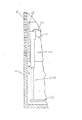
- the suction roll has a perforated roll casing 1, the interior of which is connected to a vacuum source, the perforation 7 being formed by through-holes in the roll casing 1.
- Such suction rolls are used in paper machines for dewatering and to support the guidance of the fibrous web on a belt.
- the axial displacement of the cover 6 takes place here in the form of an adjusting member 2 a linear actuator.
- the adjusting member 2 has one or more electrical leads to the outside Supply, measuring and control lines 4, the integration of the actuator in a control or regulation allows, as well as sensors for determining the position of the Push rod 3.
- the housing of the adjusting member 2 is connected via a ventilation line 5 connected to the ambient air.
- This dry and clean ambient air shows normal atmospheric pressure, which is higher than the negative pressure inside the suction roll, that is around the housing of the adjusting member 2.
- This relative Overpressure in the housing prevents moisture and dirt from entering the housing of the adjusting member 2, especially in the area where the sliding push rod 3 is guided out of the housing and thus ensures the reliable function of the adjusting member 2.
Landscapes
- Paper (AREA)
- Input Circuits Of Receivers And Coupling Of Receivers And Audio Equipment (AREA)
- Fire-Detection Mechanisms (AREA)
- Casings For Electric Apparatus (AREA)
Abstract
Description
Derartige Saugwalzen werden in Papiermaschinen zur Entwässerung sowie zur Unterstützung der Führung der Faserstoffbahn an einem Band eingesetzt.
Claims (10)
- Steuerbares Verstellglied (2) zur Lageveränderung eines Steuerobjektes in einer Maschine zur Herstellung und/oder Veredlung einer Papier-, Karton-, Tissue- oder einer anderen Faserstoffbahn, dadurch gekennzeichnet, dass
das Verstellglied (2) ein zumindest spritzwasserdichtes Gehäuse besitzt. - Steuerbares Verstellglied (2) nach Anspruch 1, dadurch gekennzeichnet, dass zumindest Teile des Gehäuses aus einem flexiblen Material bestehen.
- Steuerbares Verstellglied (2) nach Anspruch 1 oder 2, dadurch gekennzeichnet, dass
zumindest Teile des Gehäuses aus einem korrosionsbeständigem Material bestehen. - Steuerbares Verstellglied (2) nach einem der vorhergehenden Ansprüche, dadurch gekennzeichnet, dass
der Luftdruck zumindest in einem Innenbereich des Gehäuses über dem Luftdruck außerhalb des Gehäuses liegt. - Steuerbares Verstellglied (2) nach Anspruch 4, dadurch gekennzeichnet, dass zumindest ein Innenbereich des Gehäuses mit einer Überdruckquelle verbunden ist.
- Steuerbares Verstellglied (2) nach Anspruch 4, welches in einem Unterdruckbereich angeordnet ist, dadurch gekennzeichnet, dass zumindest ein Innenbereich des Gehäuses eine Verbindung mit der Umgebungsluft der Maschine hat.
- Anwendung des steuerbaren Verstellgliedes (2) zur Lageveränderung eines Steuerobjektes in einer Maschine zur Herstellung und/oder Veredlung einer Papier-, Karton-, Tissue- oder einer anderen Faserstoffbahn nach einem der vorhergehenden Ansprüche, insbesondere nach einem der Ansprüche 4 bis 6, dadurch gekennzeichnet, dass das Verstellglied (2) im Inneren einer, mit einer Unterdruckquelle verbundenen Saugwalze angeordnet ist.
- Anwendung nach Anspruch 7, dadurch gekennzeichnet, dass
das Verstellglied (2) zur Steuerung der Ausdehnung wenigstens einer Saugzone der Saugwalze dient. - Anwendung nach Anspruch 8, dadurch gekennzeichnet, dass
die Saugwalze einen perforierten Walzenmantel (1) besitzt und das Steuerobjekt von einer Abdeckung (6) der Perforation (7) an der Innenseite des Walzenmantels (1) gebildet wird. - Anwendung nach einem der vorhergehenden Ansprüche, dadurch gekennzeichnet, dass
das Verstellglied (2) als Linearantrieb ausgebildet ist.
Applications Claiming Priority (2)
| Application Number | Priority Date | Filing Date | Title |
|---|---|---|---|
| DE10258289 | 2002-12-13 | ||
| DE10258289A DE10258289A1 (de) | 2002-12-13 | 2002-12-13 | Verstellglied |
Publications (2)
| Publication Number | Publication Date |
|---|---|
| EP1428931A1 true EP1428931A1 (de) | 2004-06-16 |
| EP1428931B1 EP1428931B1 (de) | 2007-10-24 |
Family
ID=32319085
Family Applications (1)
| Application Number | Title | Priority Date | Filing Date |
|---|---|---|---|
| EP03104622A Expired - Lifetime EP1428931B1 (de) | 2002-12-13 | 2003-12-10 | Verstellglied mit spritzwasserdichtem Gehäuse |
Country Status (3)
| Country | Link |
|---|---|
| EP (1) | EP1428931B1 (de) |
| AT (1) | ATE376605T1 (de) |
| DE (2) | DE10258289A1 (de) |
Families Citing this family (1)
| Publication number | Priority date | Publication date | Assignee | Title |
|---|---|---|---|---|
| FI131692B1 (en) * | 2024-06-20 | 2025-09-24 | Valmet Technologies Oy | Adjustment system for a suction roll of a fiber web machine and a suction roll equipped with an adjustment system |
Citations (6)
| Publication number | Priority date | Publication date | Assignee | Title |
|---|---|---|---|---|
| DE236522C (de) * | ||||
| DE1034475B (de) * | 1955-05-10 | 1958-07-17 | Doerries A G O | Saugwalze fuer Papier-, Zellstoffentwaesserungs- oder dergleichen Maschinen |
| DE1206297B (de) * | 1960-03-26 | 1965-12-02 | Voith Gmbh J M | Bandlaufregler fuer ein endloses Band, wie z. B. Sieb oder Filz einer Papiermaschine |
| DE4440948A1 (de) * | 1994-11-17 | 1996-05-23 | Voith Gmbh J M | Verfahren zum Aufführen einer Papierbahn in eine Papiermaschine, Naßpartie einer Papiermaschine sowie Saugwalze für eine Papiermaschine |
| EP0857821A2 (de) * | 1997-02-05 | 1998-08-12 | Voith Sulzer Papiermaschinen GmbH | Saugeinrichtung |
| DE19822052A1 (de) * | 1996-11-20 | 1999-11-18 | Voith Sulzer Papiermasch Gmbh | Vorrichtung zur Führung einer Materialbahn |
Family Cites Families (4)
| Publication number | Priority date | Publication date | Assignee | Title |
|---|---|---|---|---|
| US2392150A (en) * | 1942-05-20 | 1946-01-01 | Beloit Iron Works | Suction roll helper drive |
| US3395073A (en) * | 1965-08-12 | 1968-07-30 | William P. Davis Sr. | Suction roll assembly |
| US4598238A (en) * | 1985-04-24 | 1986-07-01 | Albany International Corp. | Electro-mechanical shower oscillator for papermaking machine |
| US4753712A (en) * | 1987-06-05 | 1988-06-28 | Westvaco Corporation | Papermachine felt shower oscillator |
-
2002
- 2002-12-13 DE DE10258289A patent/DE10258289A1/de not_active Withdrawn
-
2003
- 2003-12-10 DE DE50308454T patent/DE50308454D1/de not_active Expired - Lifetime
- 2003-12-10 AT AT03104622T patent/ATE376605T1/de active
- 2003-12-10 EP EP03104622A patent/EP1428931B1/de not_active Expired - Lifetime
Patent Citations (6)
| Publication number | Priority date | Publication date | Assignee | Title |
|---|---|---|---|---|
| DE236522C (de) * | ||||
| DE1034475B (de) * | 1955-05-10 | 1958-07-17 | Doerries A G O | Saugwalze fuer Papier-, Zellstoffentwaesserungs- oder dergleichen Maschinen |
| DE1206297B (de) * | 1960-03-26 | 1965-12-02 | Voith Gmbh J M | Bandlaufregler fuer ein endloses Band, wie z. B. Sieb oder Filz einer Papiermaschine |
| DE4440948A1 (de) * | 1994-11-17 | 1996-05-23 | Voith Gmbh J M | Verfahren zum Aufführen einer Papierbahn in eine Papiermaschine, Naßpartie einer Papiermaschine sowie Saugwalze für eine Papiermaschine |
| DE19822052A1 (de) * | 1996-11-20 | 1999-11-18 | Voith Sulzer Papiermasch Gmbh | Vorrichtung zur Führung einer Materialbahn |
| EP0857821A2 (de) * | 1997-02-05 | 1998-08-12 | Voith Sulzer Papiermaschinen GmbH | Saugeinrichtung |
Also Published As
| Publication number | Publication date |
|---|---|
| DE10258289A1 (de) | 2004-07-29 |
| ATE376605T1 (de) | 2007-11-15 |
| EP1428931B1 (de) | 2007-10-24 |
| DE50308454D1 (de) | 2007-12-06 |
Similar Documents
| Publication | Publication Date | Title |
|---|---|---|
| EP0008814B1 (de) | Walze mit steuerbarer Durchbiegung, insbesondere für Maschinen zur Erzeugung und Verarbeitung von Bahnen aus Papier oder Kunststoff | |
| AT511975B1 (de) | Transfersaugwalze zum überführen einer materialbahn | |
| DE3832324C2 (de) | ||
| DE4411621A1 (de) | Preßmantel | |
| DE2522657C3 (de) | Walze zur Druckbehandlung von bahnförmigen Materialien | |
| EP0857821A2 (de) | Saugeinrichtung | |
| EP1428931B1 (de) | Verstellglied mit spritzwasserdichtem Gehäuse | |
| DE3715548C2 (de) | ||
| EP4004280B1 (de) | Presseneinheit | |
| EP1362948A1 (de) | Verfahren zur Entwässerung einer Faserstoffbahn | |
| WO2021013455A1 (de) | Schuhpresse | |
| DE102007014568A1 (de) | Verstelleinrichtung für eine Schuhpresswalze | |
| EP2847381B1 (de) | Dichtleiste mit integriertem schmierwasserzuführungssystem | |
| DE102007024508A1 (de) | Schuhsaugpresswalze | |
| DE69810078T2 (de) | Verfahren zur beaufschlagung der dichtungsleiste einer saugwalze und dichtungsleiste für eine walze | |
| EP1344865B1 (de) | Schallemissionsminderung | |
| CH694993A5 (de) | Tuchfuehrungsvorrichtung einer Papiermaschine oder Kartonmaschine. | |
| DE20105600U1 (de) | Saugwalze | |
| DE9011940U1 (de) | Pressenpartie einer Papiermaschine | |
| DE102005041044A1 (de) | Papiermaschinenwalze | |
| DE4301650C1 (de) | Filzspannwalze | |
| DE10336216A1 (de) | Dichtungseinrichtung für eine Papiermaschine | |
| EP1673505B1 (de) | Saug- oder blaswalze | |
| EP2128338A1 (de) | Biegeeinstellwalze | |
| EP1285990A1 (de) | Vorrichtung zum Bilden eines Langspalts |
Legal Events
| Date | Code | Title | Description |
|---|---|---|---|
| PUAI | Public reference made under article 153(3) epc to a published international application that has entered the european phase |
Free format text: ORIGINAL CODE: 0009012 |
|
| AK | Designated contracting states |
Kind code of ref document: A1 Designated state(s): AT BE BG CH CY CZ DE DK EE ES FI FR GB GR HU IE IT LI LU MC NL PT RO SE SI SK TR |
|
| AX | Request for extension of the european patent |
Extension state: AL LT LV MK |
|
| 17P | Request for examination filed |
Effective date: 20041216 |
|
| AKX | Designation fees paid |
Designated state(s): AT BE BG CH CY CZ DE DK EE ES FI FR GB GR HU IE IT LI LU MC NL PT RO SE SI SK TR |
|
| RAP1 | Party data changed (applicant data changed or rights of an application transferred) |
Owner name: VOITH PATENT GMBH |
|
| GRAP | Despatch of communication of intention to grant a patent |
Free format text: ORIGINAL CODE: EPIDOSNIGR1 |
|
| GRAS | Grant fee paid |
Free format text: ORIGINAL CODE: EPIDOSNIGR3 |
|
| GRAA | (expected) grant |
Free format text: ORIGINAL CODE: 0009210 |
|
| AK | Designated contracting states |
Kind code of ref document: B1 Designated state(s): AT BE BG CH CY CZ DE DK EE ES FI FR GB GR HU IE IT LI LU MC NL PT RO SE SI SK TR |
|
| REG | Reference to a national code |
Ref country code: GB Ref legal event code: FG4D Free format text: NOT ENGLISH |
|
| REG | Reference to a national code |
Ref country code: CH Ref legal event code: EP |
|
| REG | Reference to a national code |
Ref country code: IE Ref legal event code: FG4D Free format text: LANGUAGE OF EP DOCUMENT: GERMAN |
|
| REF | Corresponds to: |
Ref document number: 50308454 Country of ref document: DE Date of ref document: 20071206 Kind code of ref document: P |
|
| REG | Reference to a national code |
Ref country code: SE Ref legal event code: TRGR |
|
| NLV1 | Nl: lapsed or annulled due to failure to fulfill the requirements of art. 29p and 29m of the patents act | ||
| PG25 | Lapsed in a contracting state [announced via postgrant information from national office to epo] |
Ref country code: NL Free format text: LAPSE BECAUSE OF FAILURE TO SUBMIT A TRANSLATION OF THE DESCRIPTION OR TO PAY THE FEE WITHIN THE PRESCRIBED TIME-LIMIT Effective date: 20071024 Ref country code: ES Free format text: LAPSE BECAUSE OF FAILURE TO SUBMIT A TRANSLATION OF THE DESCRIPTION OR TO PAY THE FEE WITHIN THE PRESCRIBED TIME-LIMIT Effective date: 20080204 |
|
| GBV | Gb: ep patent (uk) treated as always having been void in accordance with gb section 77(7)/1977 [no translation filed] | ||
| PG25 | Lapsed in a contracting state [announced via postgrant information from national office to epo] |
Ref country code: PT Free format text: LAPSE BECAUSE OF FAILURE TO SUBMIT A TRANSLATION OF THE DESCRIPTION OR TO PAY THE FEE WITHIN THE PRESCRIBED TIME-LIMIT Effective date: 20080324 Ref country code: BG Free format text: LAPSE BECAUSE OF FAILURE TO SUBMIT A TRANSLATION OF THE DESCRIPTION OR TO PAY THE FEE WITHIN THE PRESCRIBED TIME-LIMIT Effective date: 20080124 Ref country code: SI Free format text: LAPSE BECAUSE OF FAILURE TO SUBMIT A TRANSLATION OF THE DESCRIPTION OR TO PAY THE FEE WITHIN THE PRESCRIBED TIME-LIMIT Effective date: 20071024 |
|
| REG | Reference to a national code |
Ref country code: IE Ref legal event code: FD4D |
|
| BERE | Be: lapsed |
Owner name: VOITH PATENT G.M.B.H. Effective date: 20071231 |
|
| PG25 | Lapsed in a contracting state [announced via postgrant information from national office to epo] |
Ref country code: CZ Free format text: LAPSE BECAUSE OF FAILURE TO SUBMIT A TRANSLATION OF THE DESCRIPTION OR TO PAY THE FEE WITHIN THE PRESCRIBED TIME-LIMIT Effective date: 20071024 Ref country code: MC Free format text: LAPSE BECAUSE OF NON-PAYMENT OF DUE FEES Effective date: 20071231 Ref country code: DK Free format text: LAPSE BECAUSE OF FAILURE TO SUBMIT A TRANSLATION OF THE DESCRIPTION OR TO PAY THE FEE WITHIN THE PRESCRIBED TIME-LIMIT Effective date: 20071024 |
|
| REG | Reference to a national code |
Ref country code: CH Ref legal event code: PL |
|
| EN | Fr: translation not filed | ||
| PG25 | Lapsed in a contracting state [announced via postgrant information from national office to epo] |
Ref country code: RO Free format text: LAPSE BECAUSE OF FAILURE TO SUBMIT A TRANSLATION OF THE DESCRIPTION OR TO PAY THE FEE WITHIN THE PRESCRIBED TIME-LIMIT Effective date: 20071024 Ref country code: SK Free format text: LAPSE BECAUSE OF FAILURE TO SUBMIT A TRANSLATION OF THE DESCRIPTION OR TO PAY THE FEE WITHIN THE PRESCRIBED TIME-LIMIT Effective date: 20071024 |
|
| PLBE | No opposition filed within time limit |
Free format text: ORIGINAL CODE: 0009261 |
|
| STAA | Information on the status of an ep patent application or granted ep patent |
Free format text: STATUS: NO OPPOSITION FILED WITHIN TIME LIMIT |
|
| PG25 | Lapsed in a contracting state [announced via postgrant information from national office to epo] |
Ref country code: BE Free format text: LAPSE BECAUSE OF NON-PAYMENT OF DUE FEES Effective date: 20071231 |
|
| 26N | No opposition filed |
Effective date: 20080725 |
|
| PG25 | Lapsed in a contracting state [announced via postgrant information from national office to epo] |
Ref country code: LI Free format text: LAPSE BECAUSE OF NON-PAYMENT OF DUE FEES Effective date: 20071231 Ref country code: FR Free format text: LAPSE BECAUSE OF FAILURE TO SUBMIT A TRANSLATION OF THE DESCRIPTION OR TO PAY THE FEE WITHIN THE PRESCRIBED TIME-LIMIT Effective date: 20080808 Ref country code: CH Free format text: LAPSE BECAUSE OF NON-PAYMENT OF DUE FEES Effective date: 20071231 Ref country code: IE Free format text: LAPSE BECAUSE OF FAILURE TO SUBMIT A TRANSLATION OF THE DESCRIPTION OR TO PAY THE FEE WITHIN THE PRESCRIBED TIME-LIMIT Effective date: 20071024 |
|
| PG25 | Lapsed in a contracting state [announced via postgrant information from national office to epo] |
Ref country code: GB Free format text: LAPSE BECAUSE OF FAILURE TO SUBMIT A TRANSLATION OF THE DESCRIPTION OR TO PAY THE FEE WITHIN THE PRESCRIBED TIME-LIMIT Effective date: 20071024 |
|
| PG25 | Lapsed in a contracting state [announced via postgrant information from national office to epo] |
Ref country code: GR Free format text: LAPSE BECAUSE OF FAILURE TO SUBMIT A TRANSLATION OF THE DESCRIPTION OR TO PAY THE FEE WITHIN THE PRESCRIBED TIME-LIMIT Effective date: 20080125 Ref country code: EE Free format text: LAPSE BECAUSE OF FAILURE TO SUBMIT A TRANSLATION OF THE DESCRIPTION OR TO PAY THE FEE WITHIN THE PRESCRIBED TIME-LIMIT Effective date: 20071024 |
|
| PG25 | Lapsed in a contracting state [announced via postgrant information from national office to epo] |
Ref country code: CY Free format text: LAPSE BECAUSE OF FAILURE TO SUBMIT A TRANSLATION OF THE DESCRIPTION OR TO PAY THE FEE WITHIN THE PRESCRIBED TIME-LIMIT Effective date: 20071024 |
|
| PG25 | Lapsed in a contracting state [announced via postgrant information from national office to epo] |
Ref country code: LU Free format text: LAPSE BECAUSE OF NON-PAYMENT OF DUE FEES Effective date: 20071210 |
|
| PG25 | Lapsed in a contracting state [announced via postgrant information from national office to epo] |
Ref country code: HU Free format text: LAPSE BECAUSE OF FAILURE TO SUBMIT A TRANSLATION OF THE DESCRIPTION OR TO PAY THE FEE WITHIN THE PRESCRIBED TIME-LIMIT Effective date: 20080425 Ref country code: TR Free format text: LAPSE BECAUSE OF FAILURE TO SUBMIT A TRANSLATION OF THE DESCRIPTION OR TO PAY THE FEE WITHIN THE PRESCRIBED TIME-LIMIT Effective date: 20071024 |
|
| PGFP | Annual fee paid to national office [announced via postgrant information from national office to epo] |
Ref country code: AT Payment date: 20101214 Year of fee payment: 8 |
|
| PG25 | Lapsed in a contracting state [announced via postgrant information from national office to epo] |
Ref country code: IT Free format text: LAPSE BECAUSE OF NON-PAYMENT OF DUE FEES Effective date: 20071231 |
|
| PGFP | Annual fee paid to national office [announced via postgrant information from national office to epo] |
Ref country code: SE Payment date: 20101214 Year of fee payment: 8 |
|
| PGFP | Annual fee paid to national office [announced via postgrant information from national office to epo] |
Ref country code: FI Payment date: 20111214 Year of fee payment: 9 |
|
| PGFP | Annual fee paid to national office [announced via postgrant information from national office to epo] |
Ref country code: DE Payment date: 20111222 Year of fee payment: 9 |
|
| REG | Reference to a national code |
Ref country code: SE Ref legal event code: EUG |
|
| PG25 | Lapsed in a contracting state [announced via postgrant information from national office to epo] |
Ref country code: SE Free format text: LAPSE BECAUSE OF NON-PAYMENT OF DUE FEES Effective date: 20111211 |
|
| REG | Reference to a national code |
Ref country code: AT Ref legal event code: MM01 Ref document number: 376605 Country of ref document: AT Kind code of ref document: T Effective date: 20121210 |
|
| PG25 | Lapsed in a contracting state [announced via postgrant information from national office to epo] |
Ref country code: FI Free format text: LAPSE BECAUSE OF NON-PAYMENT OF DUE FEES Effective date: 20121210 |
|
| REG | Reference to a national code |
Ref country code: DE Ref legal event code: R119 Ref document number: 50308454 Country of ref document: DE Effective date: 20130702 |
|
| PG25 | Lapsed in a contracting state [announced via postgrant information from national office to epo] |
Ref country code: AT Free format text: LAPSE BECAUSE OF NON-PAYMENT OF DUE FEES Effective date: 20121210 Ref country code: DE Free format text: LAPSE BECAUSE OF NON-PAYMENT OF DUE FEES Effective date: 20130702 |