EP1428742A1 - Fahrzeugdach - Google Patents
Fahrzeugdach Download PDFInfo
- Publication number
- EP1428742A1 EP1428742A1 EP03026597A EP03026597A EP1428742A1 EP 1428742 A1 EP1428742 A1 EP 1428742A1 EP 03026597 A EP03026597 A EP 03026597A EP 03026597 A EP03026597 A EP 03026597A EP 1428742 A1 EP1428742 A1 EP 1428742A1
- Authority
- EP
- European Patent Office
- Prior art keywords
- roof
- edge
- securing element
- vehicle roof
- module
- Prior art date
- Legal status (The legal status is an assumption and is not a legal conclusion. Google has not performed a legal analysis and makes no representation as to the accuracy of the status listed.)
- Granted
Links
- 239000006260 foam Substances 0.000 claims description 13
- 229910052751 metal Inorganic materials 0.000 claims description 6
- 239000002184 metal Substances 0.000 claims description 6
- 238000004026 adhesive bonding Methods 0.000 claims description 4
- 230000002787 reinforcement Effects 0.000 claims description 3
- 230000003014 reinforcing effect Effects 0.000 claims 1
- 230000000284 resting effect Effects 0.000 abstract 1
- 239000011324 bead Substances 0.000 description 6
- 239000000853 adhesive Substances 0.000 description 4
- 230000001070 adhesive effect Effects 0.000 description 4
- 238000005187 foaming Methods 0.000 description 2
- 239000002985 plastic film Substances 0.000 description 2
- 229920006255 plastic film Polymers 0.000 description 2
- 229910052782 aluminium Inorganic materials 0.000 description 1
- XAGFODPZIPBFFR-UHFFFAOYSA-N aluminium Chemical compound [Al] XAGFODPZIPBFFR-UHFFFAOYSA-N 0.000 description 1
- 230000005540 biological transmission Effects 0.000 description 1
- 238000006073 displacement reaction Methods 0.000 description 1
- 239000000463 material Substances 0.000 description 1
- 239000004033 plastic Substances 0.000 description 1
Images


Classifications
-
- B—PERFORMING OPERATIONS; TRANSPORTING
- B62—LAND VEHICLES FOR TRAVELLING OTHERWISE THAN ON RAILS
- B62D—MOTOR VEHICLES; TRAILERS
- B62D21/00—Understructures, i.e. chassis frame on which a vehicle body may be mounted
- B62D21/15—Understructures, i.e. chassis frame on which a vehicle body may be mounted having impact absorbing means, e.g. a frame designed to permanently or temporarily change shape or dimension upon impact with another body
-
- B—PERFORMING OPERATIONS; TRANSPORTING
- B62—LAND VEHICLES FOR TRAVELLING OTHERWISE THAN ON RAILS
- B62D—MOTOR VEHICLES; TRAILERS
- B62D25/00—Superstructure or monocoque structure sub-units; Parts or details thereof not otherwise provided for
- B62D25/06—Fixed roofs
-
- B—PERFORMING OPERATIONS; TRANSPORTING
- B62—LAND VEHICLES FOR TRAVELLING OTHERWISE THAN ON RAILS
- B62D—MOTOR VEHICLES; TRAILERS
- B62D65/00—Designing, manufacturing, e.g. assembling, facilitating disassembly, or structurally modifying motor vehicles or trailers, not otherwise provided for
- B62D65/02—Joining sub-units or components to, or positioning sub-units or components with respect to, body shell or other sub-units or components
- B62D65/06—Joining sub-units or components to, or positioning sub-units or components with respect to, body shell or other sub-units or components the sub-units or components being doors, windows, openable roofs, lids, bonnets, or weather strips or seals therefor
Definitions
- the invention relates to a vehicle roof, with a roof frame and a Roof module that is permanently and rigidly attached to the roof frame, the Roof frame has an edge pointing inwards towards the roof module.
- Modern vehicle roofs do not consist of one on the roof frame welded or integrally formed with it, but increasingly from a roof frame on which a manufactured by a supplier Roof module is permanently and rigidly fixed by gluing and screwing. permanent and rigidly attached, should not rule out that the roof module for replacement purposes can be detached from the frame in the workshop by a new one Roof module to be replaced, which then remains permanent and rigid on the Roof frame is attached.
- the roof module usually consists of Plastic, with an outer skin made of, for example, an aluminum or Plastic film that is back-foamed.
- the roof module must also on the roof frame in the event of an impact and severe deformation of the roof frame stay. In the event of a side impact, which is simulated by a pile test, comes it immediately causes a deformation of the roof frame. The attachment of the The roof module on the vehicle roof is therefore exposed to high requirements.
- the invention provides a vehicle roof in which the connection between Roof module and roof frame is further improved.
- This will be one Vehicle roof of the type mentioned achieved in that in the area Underside of the roof module, a rigid securing element is provided has at least one projecting section facing the adjacent edge, which is positioned lower than the edge.
- the rigid securing element does not worry only for a positive locking when the Roof frame, but it also reinforces the roof module itself. If the Roof frame with its inward, i.e. edge facing the securing element is shifted horizontally by deformation, the edge moves over the protruding section of the roof module so that the securing element the edge engages behind.
- Lifting the roof module off the roof frame is therefore self then prevented if the fastening of the roof frame and roof module would be destroyed in sections. If the roof frame is not deformed the projecting section to the side of the edge, so it still engages behind the edge Not. This allows the roof module to be on top of the roof frame is put on. The securing element is almost immediately adjacent the edge, so that even with small deformation of the roof frame, the edge from Securing element is "caught".
- the edge is preferably a flange-like, inward-facing extension of the Roof frame.
- the roof frame is a hollow profile, of which a horizontal, preferably closed circumferential thin sheet metal flange protrudes inwards, which serves to fasten, center and support the roof module.
- the sheet metal flange is the edge of the Roof frame, under which the securing element in the event of deformation of the roof frame attacks.
- the roof module is preferably attached to this edge, in particular by gluing and screw connections, with a corresponding adhesive bead according to the preferred embodiment runs around the edge closed.
- the securing element is, for example, a sheet metal.
- the securing element is in a Underside of an outer skin of the roof module embedded.
- This embedding can be carried out so that the securing element even is fully embedded in the back foam, which is a good attachment of the securing element in the rear foam.
- the back-foaming but sets the horizontally displaceable edge in the deformation of the roof frame no great resistance, so that the edge in the foam penetrates and extends over the deeper projecting section of the securing element can slide.
- the securing element in the preferred embodiment is a Edge of the roof frame open hollow profile, the horizontal displacement of the Edge in the direction of the securing element absorbs the edge.
- the securing element is preferably a C-profile or can e.g. also a double T profile his.
- the securing element on the underside of the roof module rotates, it can additionally serve as a reinforcement frame and have a double function.
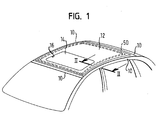
- a vehicle roof is shown, the one revolving closed Has roof frame 10.
- a Roof module 12 placed and permanently attached to the roof frame, i.e. the roof module 12 cannot be moved relative to the roof frame 10.
- the Roof module 12 can be closed by a movable cover 14 Have roof cutout 16 so that the roof module 12 has an integrated sliding roof system can include.
- the roof frame which consists of sheet metal, a Cut closed hollow profile, of which an inward-facing extension protrudes in the form of a plate-shaped, horizontal, flange-like edge 20.
- the roof module 12 is placed from above.
- the roof module 12 has an outer skin 22, preferably a deep-drawn one Plastic film, with a rear foam 24 on its underside, the Foaming is preferably made of PU material.
- a seal is on The outer edge of the roof module 12 denotes a tight seal to To ensure roof frame 10.
- the back foam 24 has in the area of Edge 20 a groove-like depression 30 in which one is closed over the entire Edge 20 circumferential adhesive bead 32 is located, by means of which the roof module 12 on Edge 20 is attached.
- screw connections 60 can also be provided his.
- the roof module 12 engages behind the roof frame 10 at no point, so that it can simply be placed on the edge 20 from above can.
- the rear foam 24 has one downward protruding bead 40, which is lower than the edge 20.
- the Bead 40 In the area of the Bead 40 is a C-shaped hollow profile open to the edge 20 or e.g. on Double-T profile 70 completely embedded in the rear foam 24.
- the Hollow profile forms a securing element 50 which acts in the event of a crash Connection roof frame to roof module.
- the lower leg 52 of the securing element 50 ie a section of the securing element 50, is lower than that Edge 20, the upper leg 54 is higher than the edge 20. As in FIG can be seen, the securing element 50 borders almost immediately on the edge 20.
- the securing element 50 forms a circumferential reinforcement profile of the Roof module 12.
- the securing element 50 only be attached along the side rails of the roof frame 10, so only in Extend the vehicle's longitudinal direction, with additional optional connecting struts between the two-sided, rail-shaped securing elements 50 could be provided.
- the mode of operation of the securing element 50 can be seen in FIG. 3.
- a horizontal, lateral force F acts on the roof frame 10.
- the roof frame 10 is laterally deformed horizontally, and its edge 20 is laterally displaced horizontally.
- the edge 20 penetrates into the rear foam 24 and is received between the legs 52, 54 in the securing element 50, and depending on the level of the force F it can abut the connecting web 56 of the legs 52, 54.
Landscapes
- Engineering & Computer Science (AREA)
- Chemical & Material Sciences (AREA)
- Combustion & Propulsion (AREA)
- Transportation (AREA)
- Mechanical Engineering (AREA)
- Manufacturing & Machinery (AREA)
- Body Structure For Vehicles (AREA)
- Vehicle Interior And Exterior Ornaments, Soundproofing, And Insulation (AREA)
Abstract
Description
- Figur 1eine Draufsicht auf ein erfindungsgemäßes Fahrzeugdach,
- Figur 2einen Schnitt längs der Linie II-II durch das Fahrzeugdach im Bereich der Verbindung zwischen Dachrahmen und Dachmodul,
- Figur 3eine Schnittansicht des in Figur 2 gezeigten Bereichs bei einem durch einen Pfahltest deformierten Dachrahmen.
Claims (16)
- Fahrzeugdach, mit einem Dachrahmen (10) und
einem Dachmodul (12), das am Dachrahmen (10) bleibend und starr befestigt ist,
wobei der Dachrahmen (10) einen zum Dachmodul (12) einwärts weisenden Rand (20) hat,
dadurch gekennzeichnet, daß im Bereich der Unterseite des Dachmoduls (12) ein starres Sicherungselement (50) vorgesehen ist, welches zumindest einen zum angrenzenden Rand (20) weisenden, vorstehenden Abschnitt hat, der tiefer als der Rand (20) positioniert ist. - Fahrzeugdach nach Anspruch 1, dadurch gekennzeichnet, daß das Sicherungselement (50) den Rand (20) nicht hintergreift.
- Fahrzeugdach nach Anspruch 1 oder 2, dadurch gekennzeichnet, daß der Rand (20) ein flanschartiger, einwärts weisender Fortsatz des Dachrahmens (10) ist.
- Fahrzeugdach nach Anspruch 3, dadurch gekennzeichnet, daß der flanschartige Fortsatz ein plattenartiger Blechabschnitt ist.
- Fahrzeugdach nach einem der vorhergehenden Ansprüche, dadurch gekennzeichnet, daß das Dachmodul (12) am Rand (20) befestigt ist.
- Fahrzeugdach nach Anspruch 5, dadurch gekennzeichnet, daß das Dachmodul (12) an dem Rand (20) durch Kleben befestigt ist.
- Fahrzeugdach nach Anspruch 6, dadurch gekennzeichnet, daß das Dachmodul (12) am Rand (20) umlaufend durch Kleben befestigt ist.
- Fahrzeugdach nach einem der vorhergehenden Ansprüche, dadurch gekennzeichnet, daß das Dachmodul am Rand (20) zusätzlich durch wenigstens eine Schraubverbindung (60) gesichert ist.
- Fahrzeugdach nach einem der vorhergehenden Ansprüche, dadurch gekennzeichnet, daß das Sicherungselement (50) ein Blech ist.
- Fahrzeugdach nach einem der vorhergehenden Ansprüche, dadurch gekennzeichnet, daß das Sicherungselement (50) in eine unterseitige Hinterschäumung (24) einer Außenhaut (22) des Dachmoduls (12) eingebettet ist.
- Fahrzeugdach nach Anspruch 10, dadurch gekennzeichnet, daß das Sicherungselement (50) vollständig in die Hinterschäumung (24) eingebettet ist.
- Fahrzeugdach nach einem der vorhergehenden Ansprüche, dadurch gekennzeichnet, daß das Sicherungselement (50) ein zum Rand (20) offenes Hohlprofil ist, welches bei horizontaler Verschiebung des Randes (20) zum Sicherungselement (50) hin den Rand (20) in sich aufnimmt.
- Fahrzeugdach nach einem der vorhergehenden Ansprüche, dadurch gekennzeichnet, daß das Sicherungselement (50) ein C-Profil ist.
- Fahrzeugdach nach einem der Ansprüche 1 bis 12, dadurch gekennzeichnet, daß das Sicherungselement ein Doppel-T-Profil ist.
- Fahrzeugdach nach einem der vorhergehenden Ansprüche, dadurch gekennzeichnet, daß das Sicherungselement (50) ein umlaufender Verstärkungsrahmen des Dachmoduls (12) ist.
- Fahrzeugdach nach Anspruch 15, dadurch gekennzeichnet, daß der Verstärkungsrahmen ringförmig geschlossen ist.
Applications Claiming Priority (2)
| Application Number | Priority Date | Filing Date | Title |
|---|---|---|---|
| DE10257398A DE10257398A1 (de) | 2002-12-09 | 2002-12-09 | Fahrzeugdach |
| DE10257398 | 2002-12-09 |
Publications (3)
| Publication Number | Publication Date |
|---|---|
| EP1428742A1 true EP1428742A1 (de) | 2004-06-16 |
| EP1428742B1 EP1428742B1 (de) | 2006-05-03 |
| EP1428742B2 EP1428742B2 (de) | 2009-02-25 |
Family
ID=32319007
Family Applications (1)
| Application Number | Title | Priority Date | Filing Date |
|---|---|---|---|
| EP03026597A Expired - Lifetime EP1428742B2 (de) | 2002-12-09 | 2003-11-19 | Fahrzeugdach |
Country Status (4)
| Country | Link |
|---|---|
| US (1) | US6869137B2 (de) |
| EP (1) | EP1428742B2 (de) |
| AT (1) | ATE325025T1 (de) |
| DE (2) | DE10257398A1 (de) |
Cited By (3)
| Publication number | Priority date | Publication date | Assignee | Title |
|---|---|---|---|---|
| EP1857351A2 (de) | 2006-05-20 | 2007-11-21 | GM Global Technology Operations, Inc. | Kraftfahrzeugkarosserie mit schmaler Dachfuge |
| DE102010009228A1 (de) * | 2010-02-25 | 2011-08-25 | Webasto AG, 82131 | Fahrzeug-Verbundbauteil mit wenigstens einem Verbindungselement |
| EP3907124A4 (de) * | 2019-03-06 | 2022-03-23 | Mazda Motor Corporation | Fahrzeugdachstruktur |
Families Citing this family (11)
| Publication number | Priority date | Publication date | Assignee | Title |
|---|---|---|---|---|
| US20030159264A1 (en) * | 2002-02-22 | 2003-08-28 | The Dow Chemical Company | Automotive roof module and method of assembly of the module to an automotive vehicle |
| DE10340022A1 (de) * | 2003-08-28 | 2005-03-24 | Webasto Ag | Fahrzeugdach |
| FR2873648B1 (fr) * | 2004-07-30 | 2006-10-13 | Webasto Systemes Carrosserie S | Pavillon permeable a la lumiere pour vehicule automobile |
| ATE386676T1 (de) * | 2005-03-18 | 2008-03-15 | Arvinmeritor Gmbh | Karosserieanbauteil, zwischenprodukt und verfahren zum herstellen eines solchen karosserieanbauteils |
| DE102005016458A1 (de) * | 2005-04-11 | 2006-10-12 | GM Global Technology Operations, Inc., Detroit | Dachkonstruktion für ein Kraftfahrzeug mit einem Flansch mit einem Längs-Auflageabschnitt |
| DE102005029849A1 (de) * | 2005-06-27 | 2007-01-04 | Webasto Ag | Verfahren zur Herstellung eines Verbund-Fahrzeugkarosserieelements |
| JP4704995B2 (ja) * | 2006-10-10 | 2011-06-22 | 株式会社クボタ | キャビンのシール構造 |
| US8167364B2 (en) * | 2009-07-23 | 2012-05-01 | International Truck Intellectual Property Company, Llc | Roof panel with insert |
| DE102013215933A1 (de) * | 2013-08-05 | 2015-02-19 | Bayerische Motoren Werke Aktiengesellschaft | Strukturbauteil eines Fahrzeugs |
| US9676426B1 (en) * | 2016-02-17 | 2017-06-13 | Honda Motor Co., Ltd. | Vehicle roof structure |
| KR102440731B1 (ko) * | 2017-11-08 | 2022-09-05 | 현대자동차주식회사 | 자동차 루프 지지구조 |
Citations (4)
| Publication number | Priority date | Publication date | Assignee | Title |
|---|---|---|---|---|
| DE19709016A1 (de) * | 1997-03-06 | 1998-09-10 | Rockwell International Gmbh | Fahrzeugdach und Verfahren zur Montage des Fahrzeugdachs an einer Karosserie |
| JP2000062646A (ja) * | 1998-08-24 | 2000-02-29 | Mazda Motor Corp | 車両の上部車体構造 |
| WO2001042051A1 (de) * | 1999-12-06 | 2001-06-14 | Webasto Vehicle Systems International Gmbh | Dachmodul |
| WO2003045762A1 (de) * | 2001-11-28 | 2003-06-05 | Daimlerchrysler Ag | Moduldach für ein kraftfahrzeug und verfahren zu seiner montage |
Family Cites Families (12)
| Publication number | Priority date | Publication date | Assignee | Title |
|---|---|---|---|---|
| DE3202594A1 (de) * | 1982-01-27 | 1983-08-11 | Ford-Werke AG, 5000 Köln | Kraftfahrzeugkarosserie mit einem fest verbundenen dach aus verbundwerkstoff |
| JPH0631008B2 (ja) | 1986-02-28 | 1994-04-27 | 日野自動車工業株式会社 | 自動車のパネル補強方法 |
| JPH09109926A (ja) | 1995-10-19 | 1997-04-28 | Toyota Autom Loom Works Ltd | センタピラー上部の結合構造 |
| JPH09175429A (ja) | 1995-12-26 | 1997-07-08 | Toyota Autom Loom Works Ltd | センタピラー上部の結合構造 |
| JPH10167114A (ja) | 1996-12-05 | 1998-06-23 | Nissan Motor Co Ltd | 自動車のルーフボウ取付構造 |
| JP2000142469A (ja) | 1998-11-11 | 2000-05-23 | Nissan Shatai Co Ltd | 車体構造 |
| DE10022915A1 (de) * | 2000-05-11 | 2001-11-22 | Webasto Vehicle Sys Int Gmbh | Fahrzeugdach mit einklebbarem Dachmodul |
| DE10105166A1 (de) † | 2001-02-06 | 2002-08-08 | Jac Products Deutschland Gmbh | Fahrzeugdach |
| JP3765239B2 (ja) | 2001-03-13 | 2006-04-12 | 日産自動車株式会社 | 車体上部構造 |
| DE10163709B4 (de) * | 2001-12-21 | 2006-05-24 | Arvinmeritor Gmbh | Modulartiges Fahrzeugdach |
| DE10233280B4 (de) * | 2002-07-23 | 2005-09-01 | Arvinmeritor Gmbh | Fahrzeugdachmodul |
| DE10254773B4 (de) * | 2002-11-22 | 2007-03-22 | Webasto Ag | Modulares Fahrzeugdach |
-
2002
- 2002-12-09 DE DE10257398A patent/DE10257398A1/de not_active Withdrawn
-
2003
- 2003-11-19 AT AT03026597T patent/ATE325025T1/de not_active IP Right Cessation
- 2003-11-19 EP EP03026597A patent/EP1428742B2/de not_active Expired - Lifetime
- 2003-11-19 DE DE50303177T patent/DE50303177D1/de not_active Expired - Lifetime
- 2003-12-03 US US10/726,844 patent/US6869137B2/en not_active Expired - Fee Related
Patent Citations (4)
| Publication number | Priority date | Publication date | Assignee | Title |
|---|---|---|---|---|
| DE19709016A1 (de) * | 1997-03-06 | 1998-09-10 | Rockwell International Gmbh | Fahrzeugdach und Verfahren zur Montage des Fahrzeugdachs an einer Karosserie |
| JP2000062646A (ja) * | 1998-08-24 | 2000-02-29 | Mazda Motor Corp | 車両の上部車体構造 |
| WO2001042051A1 (de) * | 1999-12-06 | 2001-06-14 | Webasto Vehicle Systems International Gmbh | Dachmodul |
| WO2003045762A1 (de) * | 2001-11-28 | 2003-06-05 | Daimlerchrysler Ag | Moduldach für ein kraftfahrzeug und verfahren zu seiner montage |
Non-Patent Citations (1)
| Title |
|---|
| PATENT ABSTRACTS OF JAPAN vol. 2000, no. 05 14 September 2000 (2000-09-14) * |
Cited By (4)
| Publication number | Priority date | Publication date | Assignee | Title |
|---|---|---|---|---|
| EP1857351A2 (de) | 2006-05-20 | 2007-11-21 | GM Global Technology Operations, Inc. | Kraftfahrzeugkarosserie mit schmaler Dachfuge |
| EP1857351A3 (de) * | 2006-05-20 | 2009-03-25 | GM Global Technology Operations, Inc. | Kraftfahrzeugkarosserie mit schmaler Dachfuge |
| DE102010009228A1 (de) * | 2010-02-25 | 2011-08-25 | Webasto AG, 82131 | Fahrzeug-Verbundbauteil mit wenigstens einem Verbindungselement |
| EP3907124A4 (de) * | 2019-03-06 | 2022-03-23 | Mazda Motor Corporation | Fahrzeugdachstruktur |
Also Published As
| Publication number | Publication date |
|---|---|
| EP1428742B1 (de) | 2006-05-03 |
| US20040124673A1 (en) | 2004-07-01 |
| DE50303177D1 (de) | 2006-06-08 |
| ATE325025T1 (de) | 2006-06-15 |
| US6869137B2 (en) | 2005-03-22 |
| EP1428742B2 (de) | 2009-02-25 |
| DE10257398A1 (de) | 2004-06-24 |
Similar Documents
| Publication | Publication Date | Title |
|---|---|---|
| EP1428742A1 (de) | Fahrzeugdach | |
| EP2042361B1 (de) | Fahrzeugdach | |
| EP2050600B1 (de) | Entlüftungsvorrichtung | |
| EP1448427A1 (de) | Moduldach für ein kraftfahrzeug und verfahren zu seiner montage | |
| EP1859931A1 (de) | Verbundbauteil, insbesondere transparentes Bauteil für ein Fahrzeug-Dachsystem | |
| DE102007014391B4 (de) | Seitenaufprallschutzeinrichtung, die zwischen Innen- und Außenbleche eingebaut ist | |
| EP1247672B2 (de) | Dachmodul für ein Fahrzeug | |
| EP1669245A1 (de) | Dachmodul für ein Fahrzeug | |
| DE1161155B (de) | Dachausschnitt an Schiebedaechern, insbesondere von Kraftfahrzeugen | |
| DE102006022926B4 (de) | Fahrzeug-Dachteil mit wenigstens einer Kunststoffschicht und einem damit verbundenen Rahmen | |
| EP1431092B1 (de) | Fahrzeugdach mit einem Schiebedach | |
| DE202007010766U1 (de) | Befestigungsvorrichtung | |
| EP1764286B1 (de) | Karosseriesäule | |
| DE10219957B4 (de) | Fahrzeugdach zum Einsetzen in eine Karosserie | |
| DE8119662U1 (de) | Entlüftungsdach für Kraftfahrzeuge | |
| DE102015014644A1 (de) | Seitenwand für ein Kraftfahrzeug und Baugruppe dafür | |
| DE202011051781U1 (de) | Türmodul für eine Fahrzeugtür | |
| DE10103676A1 (de) | Modular aufgebautes Fahrzeugdach | |
| DE2847331A1 (de) | Dachflaechenanordnung fuer fahrzeuge | |
| DE102008052791B4 (de) | Einrichtung zum Unterdrücken einer übermäßigen Schließbewegung bei einer Fahrzeugtür | |
| EP1346862A2 (de) | Dachrahmen eines öffnungsfähigen Fahrzeugdaches | |
| WO2019158178A1 (de) | Fahrzeugtür mit höhenverstellbarer fensterscheibe | |
| DE202015004903U1 (de) | Dachaufbau für ein Kraftfahrzeug | |
| DE102022206638A1 (de) | Dachaufbau für eine Kraftfahrzeugkarosserie | |
| WO2005095185A1 (de) | Hochdach fur ein fahrerhaus |
Legal Events
| Date | Code | Title | Description |
|---|---|---|---|
| PUAI | Public reference made under article 153(3) epc to a published international application that has entered the european phase |
Free format text: ORIGINAL CODE: 0009012 |
|
| AK | Designated contracting states |
Kind code of ref document: A1 Designated state(s): AT BE BG CH CY CZ DE DK EE ES FI FR GB GR HU IE IT LI LU MC NL PT RO SE SI SK TR |
|
| AX | Request for extension of the european patent |
Extension state: AL LT LV MK |
|
| 17P | Request for examination filed |
Effective date: 20041213 |
|
| AKX | Designation fees paid |
Designated state(s): DE FR IT NL |
|
| RBV | Designated contracting states (corrected) |
Designated state(s): AT BE BG CH CY CZ DE DK EE ES FI FR GB GR HU IE IT LI LU MC NL PT RO SE SI SK TR |
|
| 17Q | First examination report despatched |
Effective date: 20050309 |
|
| GRAP | Despatch of communication of intention to grant a patent |
Free format text: ORIGINAL CODE: EPIDOSNIGR1 |
|
| GRAS | Grant fee paid |
Free format text: ORIGINAL CODE: EPIDOSNIGR3 |
|
| GRAA | (expected) grant |
Free format text: ORIGINAL CODE: 0009210 |
|
| AK | Designated contracting states |
Kind code of ref document: B1 Designated state(s): AT BE BG CH CY CZ DE DK EE ES FI FR GB GR HU IE IT LI LU MC NL PT RO SE SI SK TR |
|
| PG25 | Lapsed in a contracting state [announced via postgrant information from national office to epo] |
Ref country code: CZ Free format text: LAPSE BECAUSE OF FAILURE TO SUBMIT A TRANSLATION OF THE DESCRIPTION OR TO PAY THE FEE WITHIN THE PRESCRIBED TIME-LIMIT Effective date: 20060503 Ref country code: SK Free format text: LAPSE BECAUSE OF FAILURE TO SUBMIT A TRANSLATION OF THE DESCRIPTION OR TO PAY THE FEE WITHIN THE PRESCRIBED TIME-LIMIT Effective date: 20060503 Ref country code: SI Free format text: LAPSE BECAUSE OF FAILURE TO SUBMIT A TRANSLATION OF THE DESCRIPTION OR TO PAY THE FEE WITHIN THE PRESCRIBED TIME-LIMIT Effective date: 20060503 Ref country code: RO Free format text: LAPSE BECAUSE OF FAILURE TO SUBMIT A TRANSLATION OF THE DESCRIPTION OR TO PAY THE FEE WITHIN THE PRESCRIBED TIME-LIMIT Effective date: 20060503 Ref country code: IE Free format text: LAPSE BECAUSE OF FAILURE TO SUBMIT A TRANSLATION OF THE DESCRIPTION OR TO PAY THE FEE WITHIN THE PRESCRIBED TIME-LIMIT Effective date: 20060503 Ref country code: FI Free format text: LAPSE BECAUSE OF FAILURE TO SUBMIT A TRANSLATION OF THE DESCRIPTION OR TO PAY THE FEE WITHIN THE PRESCRIBED TIME-LIMIT Effective date: 20060503 Ref country code: IT Free format text: LAPSE BECAUSE OF FAILURE TO SUBMIT A TRANSLATION OF THE DESCRIPTION OR TO PAY THE FEE WITHIN THE PRESCRIBED TIME-LIMIT;WARNING: LAPSES OF ITALIAN PATENTS WITH EFFECTIVE DATE BEFORE 2007 MAY HAVE OCCURRED AT ANY TIME BEFORE 2007. THE CORRECT EFFECTIVE DATE MAY BE DIFFERENT FROM THE ONE RECORDED. Effective date: 20060503 |
|
| REG | Reference to a national code |
Ref country code: GB Ref legal event code: FG4D Free format text: NOT ENGLISH |
|
| REG | Reference to a national code |
Ref country code: CH Ref legal event code: EP |
|
| REF | Corresponds to: |
Ref document number: 50303177 Country of ref document: DE Date of ref document: 20060608 Kind code of ref document: P |
|
| REG | Reference to a national code |
Ref country code: IE Ref legal event code: FG4D Free format text: LANGUAGE OF EP DOCUMENT: GERMAN |
|
| REG | Reference to a national code |
Ref country code: SE Ref legal event code: TRGR |
|
| PG25 | Lapsed in a contracting state [announced via postgrant information from national office to epo] |
Ref country code: DK Free format text: LAPSE BECAUSE OF FAILURE TO SUBMIT A TRANSLATION OF THE DESCRIPTION OR TO PAY THE FEE WITHIN THE PRESCRIBED TIME-LIMIT Effective date: 20060803 |
|
| PG25 | Lapsed in a contracting state [announced via postgrant information from national office to epo] |
Ref country code: ES Free format text: LAPSE BECAUSE OF FAILURE TO SUBMIT A TRANSLATION OF THE DESCRIPTION OR TO PAY THE FEE WITHIN THE PRESCRIBED TIME-LIMIT Effective date: 20060814 |
|
| GBT | Gb: translation of ep patent filed (gb section 77(6)(a)/1977) |
Effective date: 20060724 |
|
| PG25 | Lapsed in a contracting state [announced via postgrant information from national office to epo] |
Ref country code: PT Free format text: LAPSE BECAUSE OF FAILURE TO SUBMIT A TRANSLATION OF THE DESCRIPTION OR TO PAY THE FEE WITHIN THE PRESCRIBED TIME-LIMIT Effective date: 20061003 |
|
| ET | Fr: translation filed | ||
| PG25 | Lapsed in a contracting state [announced via postgrant information from national office to epo] |
Ref country code: MC Free format text: LAPSE BECAUSE OF NON-PAYMENT OF DUE FEES Effective date: 20061130 Ref country code: BE Free format text: LAPSE BECAUSE OF NON-PAYMENT OF DUE FEES Effective date: 20061130 |
|
| PGFP | Annual fee paid to national office [announced via postgrant information from national office to epo] |
Ref country code: IT Payment date: 20061130 Year of fee payment: 4 Ref country code: SE Payment date: 20061130 Year of fee payment: 4 |
|
| REG | Reference to a national code |
Ref country code: IE Ref legal event code: FD4D |
|
| PLBI | Opposition filed |
Free format text: ORIGINAL CODE: 0009260 |
|
| PLAX | Notice of opposition and request to file observation + time limit sent |
Free format text: ORIGINAL CODE: EPIDOSNOBS2 |
|
| 26 | Opposition filed |
Opponent name: WEBASTO AG Effective date: 20070204 |
|
| NLR1 | Nl: opposition has been filed with the epo |
Opponent name: WEBASTO AG |
|
| PLAF | Information modified related to communication of a notice of opposition and request to file observations + time limit |
Free format text: ORIGINAL CODE: EPIDOSCOBS2 |
|
| PLBB | Reply of patent proprietor to notice(s) of opposition received |
Free format text: ORIGINAL CODE: EPIDOSNOBS3 |
|
| BERE | Be: lapsed |
Owner name: ARVINMERITOR G.M.B.H. Effective date: 20061130 |
|
| PG25 | Lapsed in a contracting state [announced via postgrant information from national office to epo] |
Ref country code: AT Free format text: LAPSE BECAUSE OF NON-PAYMENT OF DUE FEES Effective date: 20061119 |
|
| PG25 | Lapsed in a contracting state [announced via postgrant information from national office to epo] |
Ref country code: GR Free format text: LAPSE BECAUSE OF FAILURE TO SUBMIT A TRANSLATION OF THE DESCRIPTION OR TO PAY THE FEE WITHIN THE PRESCRIBED TIME-LIMIT Effective date: 20060804 |
|
| PG25 | Lapsed in a contracting state [announced via postgrant information from national office to epo] |
Ref country code: EE Free format text: LAPSE BECAUSE OF FAILURE TO SUBMIT A TRANSLATION OF THE DESCRIPTION OR TO PAY THE FEE WITHIN THE PRESCRIBED TIME-LIMIT Effective date: 20060503 Ref country code: BG Free format text: LAPSE BECAUSE OF FAILURE TO SUBMIT A TRANSLATION OF THE DESCRIPTION OR TO PAY THE FEE WITHIN THE PRESCRIBED TIME-LIMIT Effective date: 20060803 |
|
| EUG | Se: european patent has lapsed | ||
| GBPC | Gb: european patent ceased through non-payment of renewal fee |
Effective date: 20071119 |
|
| PG25 | Lapsed in a contracting state [announced via postgrant information from national office to epo] |
Ref country code: TR Free format text: LAPSE BECAUSE OF FAILURE TO SUBMIT A TRANSLATION OF THE DESCRIPTION OR TO PAY THE FEE WITHIN THE PRESCRIBED TIME-LIMIT Effective date: 20060503 Ref country code: CH Free format text: LAPSE BECAUSE OF NON-PAYMENT OF DUE FEES Effective date: 20071130 Ref country code: HU Free format text: LAPSE BECAUSE OF FAILURE TO SUBMIT A TRANSLATION OF THE DESCRIPTION OR TO PAY THE FEE WITHIN THE PRESCRIBED TIME-LIMIT Effective date: 20061104 Ref country code: LU Free format text: LAPSE BECAUSE OF NON-PAYMENT OF DUE FEES Effective date: 20061119 Ref country code: LI Free format text: LAPSE BECAUSE OF NON-PAYMENT OF DUE FEES Effective date: 20071130 |
|
| REG | Reference to a national code |
Ref country code: CH Ref legal event code: PL |
|
| PG25 | Lapsed in a contracting state [announced via postgrant information from national office to epo] |
Ref country code: SE Free format text: LAPSE BECAUSE OF NON-PAYMENT OF DUE FEES Effective date: 20071120 |
|
| PG25 | Lapsed in a contracting state [announced via postgrant information from national office to epo] |
Ref country code: CY Free format text: LAPSE BECAUSE OF FAILURE TO SUBMIT A TRANSLATION OF THE DESCRIPTION OR TO PAY THE FEE WITHIN THE PRESCRIBED TIME-LIMIT Effective date: 20060503 |
|
| PG25 | Lapsed in a contracting state [announced via postgrant information from national office to epo] |
Ref country code: GB Free format text: LAPSE BECAUSE OF NON-PAYMENT OF DUE FEES Effective date: 20071119 |
|
| PUAH | Patent maintained in amended form |
Free format text: ORIGINAL CODE: 0009272 |
|
| STAA | Information on the status of an ep patent application or granted ep patent |
Free format text: STATUS: PATENT MAINTAINED AS AMENDED |
|
| 27A | Patent maintained in amended form |
Effective date: 20090225 |
|
| AK | Designated contracting states |
Kind code of ref document: B2 Designated state(s): AT BE BG CH CY CZ DE DK EE ES FI FR GB GR HU IE IT LI LU MC NL PT RO SE SI SK TR |
|
| REG | Reference to a national code |
Ref country code: ES Ref legal event code: FD2A Effective date: 20061120 |
|
| NLR2 | Nl: decision of opposition |
Effective date: 20090225 |
|
| NLR3 | Nl: receipt of modified translations in the netherlands language after an opposition procedure | ||
| PG25 | Lapsed in a contracting state [announced via postgrant information from national office to epo] |
Ref country code: IT Free format text: LAPSE BECAUSE OF NON-PAYMENT OF DUE FEES Effective date: 20071119 |
|
| REG | Reference to a national code |
Ref country code: NL Ref legal event code: SD Effective date: 20110106 |
|
| REG | Reference to a national code |
Ref country code: FR Ref legal event code: TP |
|
| REG | Reference to a national code |
Ref country code: DE Ref legal event code: R081 Ref document number: 50303177 Country of ref document: DE Owner name: ROOF SYSTEMS GERMANY GMBH, DE Free format text: FORMER OWNER: ARVINMERITOR GMBH, 63128 DIETZENBACH, DE Effective date: 20110504 |
|
| PGFP | Annual fee paid to national office [announced via postgrant information from national office to epo] |
Ref country code: FR Payment date: 20111118 Year of fee payment: 9 Ref country code: NL Payment date: 20111117 Year of fee payment: 9 |
|
| PGFP | Annual fee paid to national office [announced via postgrant information from national office to epo] |
Ref country code: DE Payment date: 20121128 Year of fee payment: 10 |
|
| REG | Reference to a national code |
Ref country code: NL Ref legal event code: V1 Effective date: 20130601 |
|
| REG | Reference to a national code |
Ref country code: FR Ref legal event code: ST Effective date: 20130731 |
|
| PG25 | Lapsed in a contracting state [announced via postgrant information from national office to epo] |
Ref country code: NL Free format text: LAPSE BECAUSE OF NON-PAYMENT OF DUE FEES Effective date: 20130601 |
|
| PG25 | Lapsed in a contracting state [announced via postgrant information from national office to epo] |
Ref country code: FR Free format text: LAPSE BECAUSE OF NON-PAYMENT OF DUE FEES Effective date: 20121130 |
|
| REG | Reference to a national code |
Ref country code: DE Ref legal event code: R119 Ref document number: 50303177 Country of ref document: DE Effective date: 20140603 |
|
| PG25 | Lapsed in a contracting state [announced via postgrant information from national office to epo] |
Ref country code: DE Free format text: LAPSE BECAUSE OF NON-PAYMENT OF DUE FEES Effective date: 20140603 |