EP1428232B1 - Mobilmagnetbetätigungsglied - Google Patents
Mobilmagnetbetätigungsglied Download PDFInfo
- Publication number
- EP1428232B1 EP1428232B1 EP02772452A EP02772452A EP1428232B1 EP 1428232 B1 EP1428232 B1 EP 1428232B1 EP 02772452 A EP02772452 A EP 02772452A EP 02772452 A EP02772452 A EP 02772452A EP 1428232 B1 EP1428232 B1 EP 1428232B1
- Authority
- EP
- European Patent Office
- Prior art keywords
- magnetic part
- magnetic
- mobile
- fixed
- actuator
- Prior art date
- Legal status (The legal status is an assumption and is not a legal conclusion. Google has not performed a legal analysis and makes no representation as to the accuracy of the status listed.)
- Expired - Lifetime
Links
- 230000005291 magnetic effect Effects 0.000 claims abstract description 353
- 230000000977 initiatory effect Effects 0.000 claims abstract 8
- 239000000758 substrate Substances 0.000 claims description 78
- 239000004020 conductor Substances 0.000 claims description 42
- 238000004804 winding Methods 0.000 claims description 29
- 239000000463 material Substances 0.000 claims description 20
- 230000005415 magnetization Effects 0.000 claims description 19
- 239000000696 magnetic material Substances 0.000 claims description 13
- 238000000034 method Methods 0.000 claims description 10
- 238000000151 deposition Methods 0.000 claims description 9
- 238000005530 etching Methods 0.000 claims description 8
- 239000004065 semiconductor Substances 0.000 claims description 8
- 238000010438 heat treatment Methods 0.000 claims description 7
- 239000011159 matrix material Substances 0.000 claims description 7
- 239000007787 solid Substances 0.000 claims description 7
- 239000002889 diamagnetic material Substances 0.000 claims description 4
- 239000003989 dielectric material Substances 0.000 claims description 2
- 238000006073 displacement reaction Methods 0.000 description 34
- 239000011347 resin Substances 0.000 description 16
- 229920005989 resin Polymers 0.000 description 16
- XUIMIQQOPSSXEZ-UHFFFAOYSA-N Silicon Chemical compound [Si] XUIMIQQOPSSXEZ-UHFFFAOYSA-N 0.000 description 8
- 230000003287 optical effect Effects 0.000 description 8
- 229910052710 silicon Inorganic materials 0.000 description 8
- 239000010703 silicon Substances 0.000 description 8
- 238000000206 photolithography Methods 0.000 description 7
- 238000004519 manufacturing process Methods 0.000 description 4
- RYGMFSIKBFXOCR-UHFFFAOYSA-N Copper Chemical compound [Cu] RYGMFSIKBFXOCR-UHFFFAOYSA-N 0.000 description 3
- 230000008901 benefit Effects 0.000 description 3
- 229910052802 copper Inorganic materials 0.000 description 3
- 239000010949 copper Substances 0.000 description 3
- 230000008021 deposition Effects 0.000 description 3
- 230000006870 function Effects 0.000 description 3
- PCHJSUWPFVWCPO-UHFFFAOYSA-N gold Chemical compound [Au] PCHJSUWPFVWCPO-UHFFFAOYSA-N 0.000 description 3
- 229910052737 gold Inorganic materials 0.000 description 3
- 239000010931 gold Substances 0.000 description 3
- 239000011810 insulating material Substances 0.000 description 3
- 230000003993 interaction Effects 0.000 description 3
- 238000005339 levitation Methods 0.000 description 3
- 230000015654 memory Effects 0.000 description 3
- 230000035939 shock Effects 0.000 description 3
- XEEYBQQBJWHFJM-UHFFFAOYSA-N Iron Chemical compound [Fe] XEEYBQQBJWHFJM-UHFFFAOYSA-N 0.000 description 2
- PXHVJJICTQNCMI-UHFFFAOYSA-N Nickel Chemical compound [Ni] PXHVJJICTQNCMI-UHFFFAOYSA-N 0.000 description 2
- 229910004298 SiO 2 Inorganic materials 0.000 description 2
- VYPSYNLAJGMNEJ-UHFFFAOYSA-N Silicium dioxide Chemical compound O=[Si]=O VYPSYNLAJGMNEJ-UHFFFAOYSA-N 0.000 description 2
- RTAQQCXQSZGOHL-UHFFFAOYSA-N Titanium Chemical compound [Ti] RTAQQCXQSZGOHL-UHFFFAOYSA-N 0.000 description 2
- QJVKUMXDEUEQLH-UHFFFAOYSA-N [B].[Fe].[Nd] Chemical compound [B].[Fe].[Nd] QJVKUMXDEUEQLH-UHFFFAOYSA-N 0.000 description 2
- CLBRCZAHAHECKY-UHFFFAOYSA-N [Co].[Pt] Chemical compound [Co].[Pt] CLBRCZAHAHECKY-UHFFFAOYSA-N 0.000 description 2
- NYOGMBUMDPBEJK-UHFFFAOYSA-N arsanylidynemanganese Chemical compound [As]#[Mn] NYOGMBUMDPBEJK-UHFFFAOYSA-N 0.000 description 2
- 238000004630 atomic force microscopy Methods 0.000 description 2
- 230000008859 change Effects 0.000 description 2
- 230000007797 corrosion Effects 0.000 description 2
- 238000005260 corrosion Methods 0.000 description 2
- 230000008878 coupling Effects 0.000 description 2
- 238000010168 coupling process Methods 0.000 description 2
- 238000005859 coupling reaction Methods 0.000 description 2
- 230000005347 demagnetization Effects 0.000 description 2
- 238000001312 dry etching Methods 0.000 description 2
- 239000003302 ferromagnetic material Substances 0.000 description 2
- 239000012530 fluid Substances 0.000 description 2
- 230000001939 inductive effect Effects 0.000 description 2
- 238000009413 insulation Methods 0.000 description 2
- 239000012212 insulator Substances 0.000 description 2
- 229910001172 neodymium magnet Inorganic materials 0.000 description 2
- 229910000938 samarium–cobalt magnet Inorganic materials 0.000 description 2
- 229910052814 silicon oxide Inorganic materials 0.000 description 2
- 239000010936 titanium Substances 0.000 description 2
- 229910052719 titanium Inorganic materials 0.000 description 2
- 229910000859 α-Fe Inorganic materials 0.000 description 2
- OKTJSMMVPCPJKN-UHFFFAOYSA-N Carbon Chemical compound [C] OKTJSMMVPCPJKN-UHFFFAOYSA-N 0.000 description 1
- 101100536354 Drosophila melanogaster tant gene Proteins 0.000 description 1
- 229910001030 Iron–nickel alloy Inorganic materials 0.000 description 1
- BQCADISMDOOEFD-UHFFFAOYSA-N Silver Chemical compound [Ag] BQCADISMDOOEFD-UHFFFAOYSA-N 0.000 description 1
- 229910001069 Ti alloy Inorganic materials 0.000 description 1
- PAZONJYZYLTGFZ-UHFFFAOYSA-N [B].[Fe].[Er] Chemical compound [B].[Fe].[Er] PAZONJYZYLTGFZ-UHFFFAOYSA-N 0.000 description 1
- QVYYOKWPCQYKEY-UHFFFAOYSA-N [Fe].[Co] Chemical compound [Fe].[Co] QVYYOKWPCQYKEY-UHFFFAOYSA-N 0.000 description 1
- BTGZYWWSOPEHMM-UHFFFAOYSA-N [O].[Cu].[Y].[Ba] Chemical compound [O].[Cu].[Y].[Ba] BTGZYWWSOPEHMM-UHFFFAOYSA-N 0.000 description 1
- XHOGEDXMEXSLPN-UHFFFAOYSA-N [P].[Mn].[Co] Chemical compound [P].[Mn].[Co] XHOGEDXMEXSLPN-UHFFFAOYSA-N 0.000 description 1
- 229910045601 alloy Inorganic materials 0.000 description 1
- 239000000956 alloy Substances 0.000 description 1
- 229910052782 aluminium Inorganic materials 0.000 description 1
- XAGFODPZIPBFFR-UHFFFAOYSA-N aluminium Chemical compound [Al] XAGFODPZIPBFFR-UHFFFAOYSA-N 0.000 description 1
- -1 aluminum-nickel-cobalt Chemical compound 0.000 description 1
- 230000004888 barrier function Effects 0.000 description 1
- 230000006399 behavior Effects 0.000 description 1
- 229910052797 bismuth Inorganic materials 0.000 description 1
- JCXGWMGPZLAOME-UHFFFAOYSA-N bismuth atom Chemical compound [Bi] JCXGWMGPZLAOME-UHFFFAOYSA-N 0.000 description 1
- 230000015556 catabolic process Effects 0.000 description 1
- 238000003486 chemical etching Methods 0.000 description 1
- GUBSQCSIIDQXLB-UHFFFAOYSA-N cobalt platinum Chemical compound [Co].[Pt].[Pt].[Pt] GUBSQCSIIDQXLB-UHFFFAOYSA-N 0.000 description 1
- KPLQYGBQNPPQGA-UHFFFAOYSA-N cobalt samarium Chemical compound [Co].[Sm] KPLQYGBQNPPQGA-UHFFFAOYSA-N 0.000 description 1
- 230000001143 conditioned effect Effects 0.000 description 1
- 238000006731 degradation reaction Methods 0.000 description 1
- 230000000694 effects Effects 0.000 description 1
- 230000008030 elimination Effects 0.000 description 1
- 238000003379 elimination reaction Methods 0.000 description 1
- 238000005265 energy consumption Methods 0.000 description 1
- 238000005516 engineering process Methods 0.000 description 1
- 230000005284 excitation Effects 0.000 description 1
- 230000002349 favourable effect Effects 0.000 description 1
- 230000005294 ferromagnetic effect Effects 0.000 description 1
- 239000011521 glass Substances 0.000 description 1
- 229910002804 graphite Inorganic materials 0.000 description 1
- 239000010439 graphite Substances 0.000 description 1
- 230000001976 improved effect Effects 0.000 description 1
- 229910052742 iron Inorganic materials 0.000 description 1
- XWHPIFXRKKHEKR-UHFFFAOYSA-N iron silicon Chemical compound [Si].[Fe] XWHPIFXRKKHEKR-UHFFFAOYSA-N 0.000 description 1
- 238000004377 microelectronic Methods 0.000 description 1
- 230000004048 modification Effects 0.000 description 1
- 238000012986 modification Methods 0.000 description 1
- 229910052759 nickel Inorganic materials 0.000 description 1
- 229910000889 permalloy Inorganic materials 0.000 description 1
- 230000008569 process Effects 0.000 description 1
- 230000001902 propagating effect Effects 0.000 description 1
- 238000005086 pumping Methods 0.000 description 1
- 238000007789 sealing Methods 0.000 description 1
- 229910052709 silver Inorganic materials 0.000 description 1
- 239000004332 silver Substances 0.000 description 1
Images


Classifications
-
- H—ELECTRICITY
- H01—ELECTRIC ELEMENTS
- H01H—ELECTRIC SWITCHES; RELAYS; SELECTORS; EMERGENCY PROTECTIVE DEVICES
- H01H37/00—Thermally-actuated switches
- H01H37/02—Details
- H01H37/32—Thermally-sensitive members
- H01H37/58—Thermally-sensitive members actuated due to thermally controlled change of magnetic permeability
-
- H—ELECTRICITY
- H01—ELECTRIC ELEMENTS
- H01F—MAGNETS; INDUCTANCES; TRANSFORMERS; SELECTION OF MATERIALS FOR THEIR MAGNETIC PROPERTIES
- H01F7/00—Magnets
- H01F7/06—Electromagnets; Actuators including electromagnets
- H01F7/08—Electromagnets; Actuators including electromagnets with armatures
-
- H—ELECTRICITY
- H01—ELECTRIC ELEMENTS
- H01H—ELECTRIC SWITCHES; RELAYS; SELECTORS; EMERGENCY PROTECTIVE DEVICES
- H01H50/00—Details of electromagnetic relays
- H01H50/005—Details of electromagnetic relays using micromechanics
-
- H—ELECTRICITY
- H01—ELECTRIC ELEMENTS
- H01F—MAGNETS; INDUCTANCES; TRANSFORMERS; SELECTION OF MATERIALS FOR THEIR MAGNETIC PROPERTIES
- H01F7/00—Magnets
- H01F7/06—Electromagnets; Actuators including electromagnets
- H01F2007/068—Electromagnets; Actuators including electromagnets using printed circuit coils
-
- H—ELECTRICITY
- H01—ELECTRIC ELEMENTS
- H01H—ELECTRIC SWITCHES; RELAYS; SELECTORS; EMERGENCY PROTECTIVE DEVICES
- H01H1/00—Contacts
- H01H1/0036—Switches making use of microelectromechanical systems [MEMS]
- H01H2001/0042—Bistable switches, i.e. having two stable positions requiring only actuating energy for switching between them, e.g. with snap membrane or by permanent magnet
-
- H—ELECTRICITY
- H01—ELECTRIC ELEMENTS
- H01H—ELECTRIC SWITCHES; RELAYS; SELECTORS; EMERGENCY PROTECTIVE DEVICES
- H01H50/00—Details of electromagnetic relays
- H01H50/005—Details of electromagnetic relays using micromechanics
- H01H2050/007—Relays of the polarised type, e.g. the MEMS relay beam having a preferential magnetisation direction
-
- H—ELECTRICITY
- H01—ELECTRIC ELEMENTS
- H01H—ELECTRIC SWITCHES; RELAYS; SELECTORS; EMERGENCY PROTECTIVE DEVICES
- H01H51/00—Electromagnetic relays
- H01H51/22—Polarised relays
- H01H51/2209—Polarised relays with rectilinearly movable armature
- H01H2051/2218—Polarised relays with rectilinearly movable armature having at least one movable permanent magnet
-
- H—ELECTRICITY
- H01—ELECTRIC ELEMENTS
- H01H—ELECTRIC SWITCHES; RELAYS; SELECTORS; EMERGENCY PROTECTIVE DEVICES
- H01H51/00—Electromagnetic relays
- H01H51/22—Polarised relays
- H01H51/2209—Polarised relays with rectilinearly movable armature
Definitions
- the subject of the present invention is a magnetic actuator with a moving magnet and in particular a microactuator that can be produced by microtechnology techniques.
- This actuator when it has several stable positions, finds its application in the production of microrelays or electrical microswitches controlling the opening or closing of an electrical contact possibly taken among several microrelais or microswitches controlling the passage, the shutter, the switching or switching a light beam, microvannes controlling the passage, sealing or switching of a fluid, micropumps controlling the pumping of a fluid.
- This actuator can be controlled so that it can take a multitude of successive positions with a nanometric precision following 5 degrees of freedom.
- Known magnetic actuators comprise a fixed magnetic part, a movable magnetic part which is mechanically connected to the fixed magnetic part.
- An electrical circuit is used to excite the moving magnetic part to make it take a working position by moving it relative to the fixed magnetic part. In the absence of excitation, the moving magnetic part is in a rest position.
- the article "Latching micro magnetic relays with multistrip permalloy cantilevers" by M. RUAN and J. SHEN published in IEEE MENS 2001 page 224 to 227 discloses a magnet magnetic microactuator made on a silicon substrate.
- the magnet is fixed, it is embedded in the silicon, it is covered by a control winding and the movable magnetic part to move is in the form of a beam with a free end and a recessed end and thus mechanically secured to the fixed magnetic part .
- the movable magnetic part is mechanically connected to the fixed magnetic part.
- This mechanical connection is difficult to achieve by collective manufacturing techniques.
- this connection limits the mobility of the mobile magnetic part, this mobility results from a deformation of one of the elements connecting the moving part to the fixed part. The speed performance of such actuators are low.
- the driving forces of the mobile magnetic part are due to the magnetic field created by at least one coil.
- Gold at constant current density a microbobine creates a force much lower than a coil of the same shape but larger.
- the performance of such microactuators therefore remains poor.
- the mass forces they are able to provide are small relative to their size.
- actuators must be electrically powered so that they remain in a working position, in the absence of power they return to a rest position.
- a method of producing a magnetic actuator in microelectronic mechanical systems (MEM) having a mechanical connection between the moving magnetic part and the fixed magnetic part is described in. WO 01/16484.
- a magnetic actuator without mechanical connection between the movable magnetic part and the fixed magnetic part is known in EP 0 179 911.
- the present invention is intended to provide a magnetic actuator that does not have all these disadvantages.
- the actuator of the present invention is particularly adapted to an embodiment in microtechnologies. It has a high movement speed, an ability to exert significant mass forces and large displacements in relation to its size. In stable position, position which can correspond to a working position, the power consumption of this actuator is zero.
- the actuator of the invention comprises a fixed magnetic part and a movable magnetic part formed by a magnet which when not glued to the fixed magnetic part is levitated without contact. When it moves and is attracted by the fixed magnetic part, it is totally guided magnetically. There is no mechanical guidance.
- the magnetic actuator according to the invention comprises a fixed magnetic part which magnetically cooperates with a mobile magnetic part and means for triggering the displacement of the mobile magnetic part.
- the mobile magnetic part comprises at least one magnet and the fixed magnetic part has at least two attraction zones on which the mobile magnetic part is likely to stick, the mobile magnetic part being levitated when it is not glued. on one of the zones of attraction, its displacement being done by magnetic guidance.
- the fixed magnetic part may be made of a material selected from the group of soft magnetic materials, hard magnetic materials, hysteresis materials, superconducting materials, diamagnetic materials, these materials being taken alone or in combination.
- the means for triggering the displacement of the mobile magnetic part are means magnetic, they can be heating means of the fixed magnetic part.
- the material of the fixed magnetic portion may have a lower Curie point than that of the magnet of the moving magnetic portion, so heating does not disturb the properties of the magnet. If this is not the case, it is necessary to take into account the thermal coupling, it is possible to thermally insulate the magnet from the moving magnetic part of the fixed magnetic part.
- the means for triggering the displacement of the moving magnetic portion creates a magnetic field in the vicinity of the moving magnetic portion.
- the means for triggering the displacement of the mobile magnetic part can be made by at least one electrical conductor.
- the actuator may comprise means for controlling the current to be circulated in the conductor at the position of the movable magnetic part so that it can take a plurality of stable levitation positions. It can then function as a positioner.
- the means for triggering the displacement of the mobile magnetic part thus serve to keep the moving magnetic part stable in levitation.
- the driver can surround the fixed magnetic part.
- the conductor may take the form of a substantially planar winding.
- the fixed and mobile magnetic parts can also be substantially flat, they can be arranged substantially in the same plane.
- the driver on the one hand and the fixed and mobile magnetic parts on the other hand can then be arranged in substantially parallel planes.
- the fixed magnetic part may be a single element which surrounds the moving magnetic part, the latter then being able to take up several stable positions inside the fixed magnetic part. It can thus have at least four degrees of freedom.
- the fixed magnetic part may be formed of several elements, the moving magnetic part being adhered to one of the elements of the fixed magnetic part or on another.
- the moving magnetic part can then take the orientation of the element on which it is glued.
- the magnetization of the fixed magnetic part and that of the movable magnetic part may be directed in the same direction or on the contrary be directed in opposite directions.
- the means for triggering the displacement of the movable magnetic part can trigger a rotational movement.
- the fixed magnetic part may comprise, at the level of at least one attraction zone, a pair of electrical contacts and the magnetic part that is mobile with at least one electrical contact, the mobile magnetic part coming to connect the two contacts of the pair when it comes stick to the area of attraction.
- the movable magnetic part may comprise a reflecting zone intended to reflect a light beam, the actuator may then be used as an optical relay or switch, as a scanner for example according to the displacement that the moving magnetic part can make.
- Such an actuator is feasible on a non-magnetic substrate, the means for triggering the displacement of the mobile magnetic part being embedded in the substrate.
- An array of actuators can be made with a plurality of magnetic actuators thus defined, these magnetic actuators being grouped together on the same support.
- the present invention also relates to a device that uses at least one magnetic actuator thus defined. It may be for example a relay, a switch, a pump, a valve, a positioner, an optical scanner.
- It also comprises a magnetization step of the magnet of the mobile magnetic part and possibly of the fixed magnetic part before the release of the mobile magnetic part.
- the step of etching the dielectric layer of the first substrate also aims to provide at least one opening for access to at least one electrical contact for powering the conductor.
- a step of producing at least one electrical contact for the supply of the conductor may take place on the second substrate, after the deposition of the conductor and before the assembly of the two substrates.
- a step of depositing a dielectric material on the surface of the second substrate can intervene before assembling the two substrates to protect the driver.
- the two substrates may be solid semiconductor substrates or SOI substrates.
- FIG. 1A to 1D which schematically illustrate an actuator according to the invention and different positions that its moving magnetic part can take.
- the fixed magnetic part 3 may comprise one or more elements based on permanent magnets 3-1 and / or magnetic material. In Figures 1, it is assumed that the fixed magnetic portion 3 comprises two elements 3-1 which are permanent magnets.
- the mobile magnetic part assembly and fixed part is supported by a non-magnetic support (not shown in FIGS. 1). When producing such an actuator in microtechnologies, it can be performed on or in a substrate as will be seen later.
- the fixed magnetic part 3 and the mobile magnetic part 1 cooperate magnetically with each other.
- the fixed magnetic portion 3 is configured to have at least two attraction zones 3-2 which separately and naturally attract the mobile magnetic part 1.
- the mobile magnetic part 1 is limited to a single permanent magnet 1-1 in the form of a parallelepiped plate. It is located between the two permanent magnets 3-1 of the fixed magnetic part 3 which are also in the form of a parallelepiped plate.
- the zones of attraction 3-2 are lateral faces of the fixed magnets 3-1.
- the movable magnet 1-1 can be glued either to one of the faces 3-2 of the fixed magnet of the right or to one of the faces 3-2 of the fixed magnet of the left, these two faces being in opposite.
- the three magnets 1-1 and 3-1 are aligned and extend substantially in the x, y plane.
- the mobile magnetic part 1 is devoid of permanent mechanical connection with the fixed part 2.
- the mobile magnetic part 1 is not bonded to one of the attraction zones 3-2, it is free, levitated without contact, thanks to the interactions it has with the fixed magnetic part 3. During its displacement, it is guided magnetically.
- the means 4 for triggering the displacement of the movable magnetic part 1 have the function of modifying the forces interacting on the moving magnetic part 1 and thus of modifying the balance of the fixed magnetic magnetic 1-part mobile part assembly 3. initiate the displacement of the mobile magnetic part 1 but then the displacement is due to the interactions between the fixed magnetic part 3 and the mobile magnetic part 1.
- the means 4 for triggering the displacement are magnetic means. They can act next several different physical principles. They can, by a localized increase of the temperature, modify the magnetic characteristics of the fixed magnetic part 3 at the zone of attraction 3-2 on which is glued the mobile magnetic part 1. According to a variation, they can create a magnetic field at the mobile magnetic part, this magnetic field modifies the magnetic characteristics of the assembly and sets in motion the moving magnetic part.
- each of the magnets 3-1 of the fixed magnetic part 3 is provided with a heating resistor R.
- This resistor R may be deposited on one faces of the magnets 3-1 of the fixed magnetic part. It can be made of copper, silver, gold, aluminum for example.
- a light beam for example a laser beam which would irradiate the fixed magnetic portion at the area whose magnetic properties are to be modified.
- the fixed magnetic part 3 can then be made of a material whose Curie point is low, for example less than or equal to 100 ° C. Its magnetic properties are likely to disappear with an increase in temperature.
- the material used is magnetic below 100 ° C and non-magnetic above 100 ° C.
- the temperature reached by the fixed magnetic portion during heating should not disturb the behavior of the magnet of the moving magnetic part which can then have a higher Curie point.
- the Curie point of the magnet of the moving magnetic part may not be less than that of the fixed magnetic part, but in this case the magnet of the mobile magnetic part will have a weak thermal coupling with the fixed magnetic part of not to heat up when the fixed magnetic part heats up.
- the movable magnet 1-1 is glued to the fixed magnet 3-1 of the left. Once in such a stable position, the magnetic forces are so great that even a very violent shock will not succeed in detaching it.
- mobile and fixed magnets with dimensions of 50 ⁇ m x 50 ⁇ m x 10 ⁇ m, with a magnetization of 1 Tesla, it would take a shock well above 1000G to be able to take off and move it 1 .mu.m.
- the movable magnet 1-1 comes off, enters into motion and is attracted by the right fixed magnet 3-1. It sticks on the fixed magnet 3-1 on the right and takes another stable position.
- the movable magnet 1-1 is levitating between the fixed magnet 3-1 of the left and the fixed magnet 3-1 of the right which attracts it.
- the moving magnet 1-1 is now bonded to the fixed magnet 3-1 from the right, he stays in that position which is stable. The fixed magnet 3-1 on the left, which is no longer heated, resumes its magnetic properties.
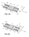
- the fixed magnetic part 3 and the mobile magnetic part 1 can be provided with electrical contacts as illustrated in FIGS. 2A, 2B, 2C, 2D.
- At least one attraction zone 3-2 of the fixed magnetic portion 3 is provided with a pair of electrical contacts C1, C2, these contacts extend beyond the attraction zone 3-2 to be accessible.
- the mobile magnetic part 1 is provided with at least one electrical contact C. When the mobile magnetic part 1 is bonded to the attraction zone 3-2, its contact C electrically connects the two contacts C1, C2 of the pair. One can thus realize an electrical relay.
- the two fixed magnets 3-1 are provided with contacts C1, C2 and the movable magnet 1-1 has two of its faces 1-2 each having a contact C (contact C on its face 1-2 which comes into contact with the fixed magnet 3-1 of the left is not visible in Figures 2A, 2B).
- a device 20 for example of the electric switch type, comprising at least one magnetic actuator according to the invention.
- the fixed magnetic portion instead of being formed of two elements 3-1 each having a pair of electrical contacts is formed of two pairs of elements 3-1a, 3-1b.
- the elements 3-1a, 3-1b of a pair are side by side but disjoint.
- Each of the elements 3-1a, 3-1b of the pair is provided with an electrical contact C1, C2 respectively. There is no change for the moving magnetic part 1.
- the magnetization of the fixed and movable magnetic parts is directed in the same direction along the x axis.
- FIG. 3A The only difference with respect to the preceding figures is at the level of the means 4 for triggering the displacement of the mobile magnetic part 1.
- Their principle is now to create a magnetic field in the vicinity of the moving magnetic part.
- These means 4 may be made by at least one conductor 4-1 intended to be traversed by an electric current to generate the magnetic field.
- the driver 4-1 can have a large number of configurations, for example it can take the form of an open loop or a winding with one or more turns. In the remainder of the description, when the term "winding" has been used, it could equally well be a conductor taking a form suitable for generating the magnetic field without being a winding.
- FIG. 3A there is a single winding 4-1 substantially flat extending in an x plane, y.
- the winding comprises one or more turns wound around an empty central part, the fixed magnetic part 3 is in the vicinity of the turns and the moving magnetic part 1, when it is levitated is close to the central part of the winding 4-1.
- a current pulse travels through this winding 4-1, a magnetic field is created and it has the effect of modifying the magnetic equilibrium of the fixed magnetic 3 and mobile 1 parts and triggering the displacement of the mobile magnetic part 1 of a stable position towards another.
- the pulse necessary for the passage from one position to another may be less than 5 ⁇ s for the actuator whose characteristics have been given above.
- the rest of the actuator does not consume energy.
- An actuator that would switch a thousand times per second would consume about 2mW which is very low. With magnetic materials of very good quality, this consumption could be reduced.
- the fixed magnetic part 3 can rest on the winding 4-1 while the mobile magnetic part 1 is levitated above. Appropriate insulations are inserted between the fixed magnetic part and the winding.
- the direction of movement is conditioned by the direction of the current flowing in the winding 4-1. For example, with a current flowing in the winding 4-1 clockwise and a magnetization in the fixed magnets 3-1 and mobile 1-1 in the x-axis direction, the moving magnet 3-1 will be attracted to the left 3-1 fixed magnet.
- the means 4 for triggering the displacement of the mobile magnetic part 1 are now made by two conductors 40 which each surround one of the elements of the fixed magnetic part. They take the form of tubular windings.
- soft magnetic materials such as iron, nickel, iron-nickel alloys, iron-cobalt, iron-silicon
- Hard magnetic materials correspond to magnets such as ferrite magnets, samarium-cobalt magnets, neodymium-iron-boron magnets, platinum-cobalt magnets. Their magnetization depends little on the external magnetic field.
- Hysteresis materials for example of aluminum-nickel-cobalt (AlNiCo) type, have properties that are between those of soft magnetic materials and those of hard magnetic materials. They are sensitive to the magnetic field in which they are. When with diamagnetic materials such as bismuth or pyrolitic graphite, their magnetization is collinear with the inducing magnetic field but of opposite direction.
- the superconducting materials could be nobium-titanium alloys (NbTi), yttrium-barium-copper-oxygen (YBaCuO) for example.
- the magnet of the mobile magnetic part may be made for example of ferrite, samarium-cobalt, neodymium-iron-boron, platinum-cobalt.
- the low Curie magnetic materials which are suitable for producing the fixed magnetic part are, for example, the manganese-arsenic (MnAs), cobalt-manganese-phosphorus (CoMnP), erbium-iron-boron (ErFeB) alloys.
- MnAs manganese-arsenic
- CoMnP cobalt-manganese-phosphorus
- ErFeB erbium-iron-boron alloys.
- the actuator according to the invention is transformed into a positioner.
- the mobile magnetic part 1 is capable of taking a plurality of intermediate positions between the two extreme stable positions which correspond to the cases where it is glued to the fixed magnetic part 3.
- the means for triggering the displacement of the moving magnetic part then serve to keep the moving magnetic part in a stable position while it is levitating.
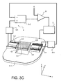
- a device 5 which detects the position of the mobile magnetic part 1.
- the signal delivered by this device 5 is compared with a setpoint K in a comparator 6 and the result of this comparison serves to control a power source 7 provided to power the driver 4-1.
- the device 5 which detects the position of the mobile magnetic part 1 may comprise, associated with each of the fixed magnetic elements 3-1, a capacitive position sensor 5-1 which measures the capacitance existing between the fixed magnetic element 3-1 with which it is associated with and the moving magnetic part 1.
- a differentiator device 5-2 receives the signals coming from the two capacitive position sensors 5-1, makes the difference and delivers a signal representative of the position of the mobile magnetic part 1.
- FIGS. 1 to 3 have the advantage of allowing the use of medium quality magnets. Indeed a magnet creates a magnetic field that tends to demagnetize it. The intensity of this phenomenon depends on the direction of magnetization with respect to the shape of the magnet. This phenomenon of demagnetization is more intense when the magnetization follows a small side of the magnet and it is less intense when the magnetization is directed along a long side of the magnet, which is the case in these figures, with a magnetization directed along the x axis.
- the magnets compatible with the collective manufacturing technologies are sensitive to demagnetization, but by magnetizing them in a direction that follows one of their long side, this disadvantage is mitigated.
- the magnets that they belong to the fixed magnetic part or the mobile magnetic part can finally be realized in a simple way and in one operation because they are all magnetized in the same direction.
- FIG. 4 shows a variant of an actuator according to the invention made on a substrate 9, for example a silicon wafer. It can have a thickness of 300 ⁇ m if the mobile and fixed magnetic parts have the dimensions mentioned above (50 ⁇ m x 50 ⁇ m x 10 ⁇ m)
- the fixed magnetic part 3 is attached to the surface of the substrate 9, the mobile magnetic part 1, when it is not glued to the fixed magnetic part 3, floats above the substrate 9, in the magnetic field created by the fixed magnetic part 3, as to the means 4 for triggering the displacement of the mobile magnetic part 1, they are embedded in the substrate 9.
- the mobile 1 and fixed 3 magnetic parts can be made similar to those of Figures 1 to 3, but other configurations are possible. Instead of being formed by two elements, the fixed magnetic part could be massive. Instead of being made from a magnet, it could be made of a ferromagnetic material.
- the magnetization of the fixed and mobile magnetic parts now follow the z-axis instead of following the x-axis.
- This magnetization follows the thickness of the mobile and fixed magnetic parts which have the form of plates. But these magnetizations are in opposite directions.
- the two magnet plates 3-1 or ferromagnetic material of the fixed magnetic part 3 have a magnetization in the same direction and the magnetization of the magnet 1-1 of the movable magnetic part 1 is of opposite direction. If the plates 3-1 of the fixed magnetic part 3 are ferromagnetic, their magnetization depends on that of the magnet 1-1 of the mobile magnetic part 1, it is naturally opposite to that of the mobile magnetic part 1.
- the means 4 for triggering the displacement of the mobile magnetic part 1 are suitably modified to be effective. They are formed in this example of two coils 410, 411 substantially planar, placed side by side in the same plane, along the x axis. Each of these windings 410, 411 is comparable to that shown in Figure 3A. But now the moving magnetic part 1 is straddling portions of turn of each of the windings 410, 411.
- the two coils 410, 411 can be supplied in series, in parallel or independently of one another. No power source has been shown to avoid overloading the figure.
- the creation of an asymmetry in the currents flowing through the two coils 410, 411 can make it possible to drive the mobile magnetic part 1 in rotation about the y axis when it is levitating.
- this portion 10 is on the upper main face of the mobile magnetic part 1. It can be thus realize an optical scanner.
- the portion 10 is on an edge of the movable magnetic part 1 or on its lower main face if the substrate 9 allows it. The latter could be provided with an opening or let the light beam F if it is made of glass for example.
- the mobile magnetic part 1 has a resonant frequency and by using this frequency, it is possible to make an optical scanner with very low power consumption.
- This power supply corresponds to that injected into the windings to obtain the rotation of the moving magnetic part when it is in levitation and thus the desired scanning of the light beam F.
- At the resonance it is necessary to supply very little energy to the system for the to oscillate. In theory, an impulse would be enough to make it oscillate indefinitely.
- Figure 5 illustrates a variant of the previous configuration.
- the two elements 3-1 of the fixed magnetic part 3 instead of being in the same plane, have a dissymmetry of shape or position with respect to the mobile magnetic part 1.
- they are now inclined. one compared to the other.
- they are inclined around the x axis.
- the mobile magnetic part 1 coming to stick on one of the elements 3-1 of the fixed magnetic part takes the same inclination as him. If the mobile magnetic part 1 is provided with a reflective portion 10, a light ray F which is reflected on this portion 10 will be deflected with a inclination which depends on that of the fixed magnetic element on which sticks the moving magnetic part. An optical switch is then produced.
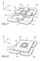
- FIG. 6 is an actuator according to the invention which is deduced from the configuration of FIG. 4.
- the means 4 for triggering the displacement of the mobile magnetic part 1 comprise four windings 401, 402, 403, 404 planes, situated in a same plane x, y and arranged in matrix.
- the moving magnetic portion overlaps a turn portion of the four windings 401, 402, 403, 404 and each member 3-1 of the fixed magnetic portion 3 overlaps a turn portion of two of the windings 401, 402, 403, 404.
- Two degrees of freedom of the moving magnetic part are controlled.
- the mobile magnetic part 1 is similar to that of FIG. means 4 to trigger the movement also with the exception of the fifth winding 405 which has been omitted, for the sake of simplification but which could be present.
- the difference now lies in the fixed magnetic means 3 which now comprise four fixed magnetic elements 31, 32, 33, 34 forming a cross with the moving magnetic part 1.
- Each of these elements 31, 32, 33, 34 of the part fixed magnetic magnet 3 overlaps a turn portion of two coils respectively (401, 404), (401, 402), (402, 403), (403, 404).
- the mobile magnetic part 1 can then be controlled in the same directions as those of FIG. 6.
- the addition of the fifth winding could be envisaged to obtain a displacement in a direction perpendicular to the plane of the first windings 401, 402, 403, 404.
- the actuator can take four stable positions, the mobile magnetic part 1 can stick on each of the four fixed magnetic elements 31, 32, 33, 34.
- the fixed magnetic portion 3 is formed of a single element 30 which surrounds the mobile magnetic part 1. The mobile magnetic part 1 can then take an infinity of stable positions when it comes to stick against the fixed magnetic element 30. It is then possible to obtain a positioner.
- the fixed magnetic portion has been shown as a hollowed square plate.
- Other shapes are of course conceivable, for example ring.
- the moving magnetic part must have a shape compatible with that of the fixed magnetic part.
- a ring shape for the fixed magnetic portion would correspond to a disk shape for the moving magnetic portion.
- the control of the position of the moving magnetic part is similar to that described in FIGS. 6 and 7.
- a fifth coil could be added to control the position in a plane perpendicular to that of the first four coils.
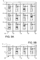
- FIGS. 9A, 9B A device with a plurality of actuators A according to the invention has been shown in FIGS. 9A, 9B.
- the various actuators A are arranged in matrix M on the same support 9, at the intersection between n line conductors 11 to 13 and m column conductors j1 to j4 (n and m are integers, n and m may be different or not).
- signals propagating on a web formed of n line conductors i1 to i3 can be switched to the m column conductors j1, j2, j3, j4.
- These signals can be electrical or optical signals depending on the nature of the actuators A. Due to the bistability of the actuators A of the matrix M, the latter can be programmed and keep its configuration without the need to power it.
- actuators operate in positioners, such a matrix makes it possible to access several memories mounted in parallel, each position of the positioner corresponding to a memory position of one of the memories.
- the actuators can be grouped into a particular matrix B as in FIG. 9B with a line conductor 11 and several column conductors j1 to j4. By connecting a bus to the line conductor i1, the signals it conveys can be directed to the different column conductors j1 to j4 according to the state of the various actuators A.
- microactuators have their magnetic parts movable and fixed carried by magnets.
- the means for triggering the displacement of the mobile magnetic part are made by coils.
- the advantage of this process is to be able to make several at the same time on the same substrate.
- the microactuator is completely embedded in the substrate made in two assembled parts.
- the triggering means are embedded in the substrate, also made in two assembled parts, the moving and fixed magnetic parts being placed on the substrate.
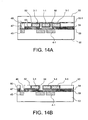
- the two parts are solid classical semiconductor substrates while in Figs. 14A, 14B, one of them is a massive conventional substrate while the other is an SOI substrate (acronym silicon on insulator, for silicon on insulator).
- SOI substrate an SOI substrate
- Such a silicon substrate has a layer of insulating material 93-1, silicon oxide buried in the silicon. Its advantage is that when performing an etching operation, the layer of insulating material can serve as a barrier layer.
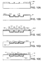
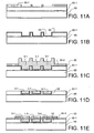
- a first solid classical substrate 91 made of semiconductor material, or SOI type 93 the micro-magnets will be produced (FIGS. 10A to 10I and 11A to 11I).
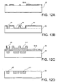
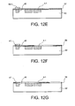
- a second solid substrate 92 made of semiconductor material or of the SOI type the displacement triggering means taking the form of one or more conductors which can be arranged in winding (FIGS. 12A to 12G) will be realized.
- FIG. 12B the position of the layer of insulating material of an SOI substrate is shown schematically by dotted lines.
- 93 crates 51 are etched for the magnets.
- the engraving can be a dry etching.
- the etching stops on the oxide layer 93-1. We remove the resin 50-1.
- a conductive bonding sub-layer 52 is deposited on the substrate 91, 93. In fact this variant is only found in FIG. 11B.
- FIG. 10B there are two attachment sublayers 52-1, 52-2, the second 52-2 being inserted between the first 52-1 and the substrate 91. It allows a good adhesion to the substrate 91 of the first underlayer 52-1. It also allows protection of the movable magnet 1-1, made subsequently, against corrosion.
- the first undercoat can be gold and the second titanium.
- the deposition zone of the magnets is defined by photolithography.
- the resin layer employed is 50-2.
- the magnets 3-1, 1-1 are deposited electrolytically.
- the material used may be cobalt-platinum ( Figures 10C, 11C).
- a planarization step of the magnets is carried out and then a step of removing the sub-layer 52 at the surface (FIG. 10D) or of the two sub-layers 52-1, 52-2 ( Figure 11D).
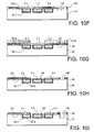
- a conductive layer 53 is then deposited on the surface intended to make the electrical contacts C1, C2, C on the magnets 3-1, 1-1.
- the geometry of the contacts C1, C2, C is defined by photolithography.
- the resin has the reference 50-3 ( Figures 10E, 11E). Since all the magnets are made at the same time, the movable magnet 1-1 also carries a conductive layer on its upper face, it has a role of protection against corrosion.
- the next step is a step of etching the conductive layer 53 to delimit the contacts C1, C2, C.
- the resin 50-3 is then removed.
- An insulating layer 54 made of SiO 2 for example, is deposited on the surface and then a planarization step is carried out (FIGS. 10F, 11F).
- At least one opening 46 will be defined to make the feed contacts of the conductor or conductors to be made accessible on the second substrate accessible, as well as the geometry of the free space 58 surrounding the mobile magnetic part 1-1 so as to allow his displacement.
- This step is a photolithography step and the resin employed is referenced 50-4 (FIGS. 10G, 11G).
- the insulation layer 54 is then etched where there is no resin 50-4. Resin 50-4 is removed ( Figures 10H, 11H). The moving magnet 1-1 is then exposed as well as its surroundings to the fixed magnets 3-1.
- the second substrate 92 On the second substrate 92, it defines the geometry of the conductor 4-1 and its ends 45 to carry the feed contacts by photolithography.
- the resin employed has the reference 50-5 (FIG. 12A).
- Photolithography is defined as the deposition area of the conductor.
- the resin used has the reference 50-6.
- the conductor 4-1 is deposited electrolytically, its referenced ends 45 are clearly visible (FIG. 12C).
- the deposit may be copper.
- a conductive layer 57 for making the power supply contacts 47 of the conductor 4-1 these contacts 47 covering the ends 45 of the conductor 4-1.
- the geometry of the contacts 47 is defined by photolithography, the resin used for this bearing the reference 50-7 (FIG. 12E).
- the conductive layer 57 is then etched so as to remove it wherever it is not protected by the resin 50-7.
- an insulating layer 59 is deposited on the surface. It can be made of silicon oxide SiO 2 . It will isolate the conductor 4-1 magnets 3-1, 1-1 during the assembly of the first substrate 91, 93 and the second substrate 92 ( Figure 12F).
- Planarization is carried out on the surface and the contacts 47 are exposed (FIG. 12G).
- the substrate of FIG. 10I will be assembled by bonding them face to face to the substrate of FIG. 12G (FIG. 13A) or the substrate of FIG. 11I to the substrate of FIG. 12G (FIG. 14A).
- the first substrate 91, 93 will be totally or partially removed. It may be a mechanical thinning and / or chemical etching.
- the substrate 91 has been completely removed while in Fig. 14B, the removal has stopped on the oxide layer 93-1 and the silicon of the substrate 93 underneath it remains in place. It ends with the removal of the oxide layer 93-1.
- the magnets 3-1, 1-1 are then embedded in the substrate formed by the two assembled parts 92 and 93 while in FIG. 13B they are on the surface of the substrate 92.
- the actuator according to the invention if it occupies a volume greater than about 1 cubic centimeter, risk to be sensitive to the external environment such as vibrations and shocks. Its performance may not be optimal in such disturbed environments. On the other hand, against all odds, with smaller dimensions its performances are greatly improved whatever the environment.
- the interaction between the fixed and mobile magnetic parts is favorable and does not bring performance degradation as in the case of a much larger actuator.
Landscapes
- Physics & Mathematics (AREA)
- Electromagnetism (AREA)
- Engineering & Computer Science (AREA)
- Power Engineering (AREA)
- Thermal Sciences (AREA)
- Micromachines (AREA)
- Reciprocating, Oscillating Or Vibrating Motors (AREA)
- Magnetic Bearings And Hydrostatic Bearings (AREA)
- Vehicle Body Suspensions (AREA)
Claims (31)
- Magnetisches Betätigungsglied, einen stationären magnetischen Teil (3), der magnetisch kooperiert mit einem mobilen magnetischen Teil (1), und Einrichtungen (4) zur Auslösung der Verschiebung des mobilen magnetischen Teils (1) umfassend,
dadurch gekennzeichnet, dass der mobile magnetische Teil (1) wenigstens einen Magnet (1-1) umfasst, und dadurch, dass der stationäre magnetische Teil (3) wenigstens zwei Anziehungszonen (3-2) umfasst, an denen der mobile magnetische Teil kleben kann, wobei der mobile magnetische Teil (1), wenn er nicht an einer der Anziehungszonen (3-2) klebt, sich im magnetischen Schwebezustand befindet und seine Verschiebung mittels magnetischer Führung erfolgt, - Magnetisches Betätigungsglied nach Anspruch 1, dadurch gekennzeichnet, dass der stationäre magnetische Teil (3) aus einem Material ist, das gewählt wird aus der Gruppe der weichmagnetischen Werkstoffe, der hartmagnetischen Werkstoffe, der Hysteresis-Werkstoffe, der Supraleiter-Werkstoffe, der diamagnetischen Werkstoffe, wobei diese Materialien einzeln oder kombiniert verwendet werden.
- Magnetisches Betätigungsglied nach einem der Ansprüche 1 oder 2, dadurch gekennzeichnet, dass die Einrichtungen (4) zur Auslösung der Verschiebung des mobilen magnetischen Teils (1) magnetische Einrichtungen sind.
- Magnetisches Betätigungsglied nach Anspruch 3, dadurch gekennzeichnet, dass die Einrichtungen (4) zur Auslösung der Verschiebung des mobilen magnetischen Teils (1) Heizeinrichtungen (R) des stationären magnetischen Teils (3) sind.
- Magnetisches Betätigungsglied nach Anspruch 4, dadurch gekennzeichnet, dass das Material des stationären magnetischen Teils (3) eine Curie-Temperatur aufweist, die niedriger ist als diejenige des Magnets (1-1) des mobilen magnetischen Teils.
- Magnetisches Betätigungsglied nach Anspruch 4, dadurch gekennzeichnet, dass der Magnet (1-1) des mobilen magnetischen Teils (1) von dem stationären magnetischen Teil (3) thermisch isoliert ist.
- Magnetisches Betätigungsglied nach Anspruch 3, dadurch gekennzeichnet, dass die Einrichtungen (4) zur Auslösung der Verschiebung des mobilen magnetischen Teils (1) in der Nähe bzw. Umgebung des mobilen magnetischen Teils (1) ein Magnetfeld erzeugen.
- Magnetisches Betätigungsglied nach Anspruch 7, dadurch gekennzeichnet, dass die Einrichtungen (4) zur Auslösung der Verschiebung des mobilen magnetischen Teils (1) durch wenigstens einen Leiter (4-1) gebildet werden, in dem ein Strom fließen kann.
- Magnetisches Betätigungsglied nach Anspruch 8, dadurch gekennzeichnet, dass es Einrichtungen (5, 6) umfasst, um den Strom, der in dem Positionierungsleiter (4-1) des mobilen magnetischen Teils (1) fließt, derart zu regeln, dass er eine Vielzahl stabiler magnetischer Schwebezustandspositionen einnehmen kann.
- Magnetisches Betätigungsglied nach einem der Ansprüche 8 oder 9, dadurch gekennzeichnet, dass der Leiter (40) den stationären magnetischen Teil (3) umgibt.
- Magnetisches Betätigungsglied nach einem der Ansprüche 8 bis 10, dadurch gekennzeichnet, dass der Leiter (4-1) die Form einer im Wesentlichen planen Wicklung annimmt.
- Magnetisches Betätigungsglied nach einem der Ansprüche 1 bis 11, dadurch gekennzeichnet, dass die stationären (3) und mobilen (1) magnetischen Teile im Wesentlichen plan sind.
- Magnetisches Betätigungsglied nach Anspruch 12, dadurch gekennzeichnet, dass die stationären (3) und mobilen (1) magnetischen Teile im Wesentlichen in derselben Ebene angeordnet sind.
- Magnetisches Betätigungsglied nach einem der Ansprüche 1 bis 13, dadurch gekennzeichnet, dass einerseits der Leiter (4-1) und andererseits die stationären (3) und mobilen (1) magnetischen Teile in im Wesentlichen parallelen Ebenen angeordnet sind.
- Magnetisches Betätigungsglied nach einem der Ansprüche 1 bis 14, dadurch gekennzeichnet, dass der stationäre magnetische Teil (3) durch ein Element (30) gebildet wird, das den mobilen magnetischen Teil (1) umgibt.
- Magnetisches Betätigungsglied nach einem der Ansprüche 1 bis 15, dadurch gekennzeichnet, dass der stationäre magnetische Teil (3) durch mehrere Elemente (3-1) gebildet wird, wobei der mobile magnetische Teil (1) an einem der Elemente (3-1) des stationären magnetischen Teils (3) oder an einem anderen klebt.
- Magnetisches Betätigungsglied nach Anspruch 16, bei dem der stationäre magnetische Teil (3) mehrere in verschiedene Ebenen orientierte Elemente (3-1) umfasst, wobei der mobile magnetische Teil (1) die Orientierung des Elements (3-1) annimmt, an dem er klebt.
- Magnetisches Betätigungsglied nach einem der Ansprüche 1 bis 17, dadurch gekennzeichnet, dass die Magnetisierung des stationären magnetischen Teils (3) und die des mobilen magnetischen Teils (1) dieselbe Richtung aufweisen.
- Magnetisches Betätigungsglied nach einem der Ansprüche 1 bis 17, dadurch gekennzeichnet, dass die Magnetisierung des stationären magnetischen Teils (3) und die des mobilen magnetischen Teils (1) entgegengesetzte Richtungen aufweisen.
- Magnetisches Betätigungsglied nach Anspruch 17, dadurch gekennzeichnet, dass die Einrichtungen (4) zur Auslösung der Verschiebung des mobilen magnetischen Teils (1) fähig sind, eine Rotationsverschiebung auszulösen.
- Magnetisches Betätigungsglied nach einem der Ansprüche 1 bis 20, dadurch gekennzeichnet, dass der stationäre magnetische Teil (3) auf Höhe einer Anziehungszone (3-2) ein Paar elektrischer Kontakte (C1, C2) umfasst, und dadurch, dass der mobile magnetische Teil (1) wenigstens einen elektrischen Kontakt (C) umfasst, wobei der mobile magnetische Teil (1) die beiden Kontakte (C1, C2) des Paars verbindet, wenn er an der Anziehungszone (3-2) klebt.
- Magnetisches Betätigungsglied nach einem der Ansprüche 1 bis 21, dadurch gekennzeichnet, dass der mobile bewegliche Teil (1) eine Reflexionszone (10) umfasst, die dazu dient, einen Lichtstrahl (F) zu reflektieren.
- Magnetisches Betätigungsglied nach einem der Ansprüche 1 bis 22, dadurch gekennzeichnet, dass es auf einem unmagnetischen Substrat (9) realisiert ist, wobei die Einrichtungen (4) zur Auslösung der Verschiebung des mobilen beweglichen Teils (1) in das Substrat eingebettet sind.
- Matrix für magnetische Betätigungsglieder, dadurch gekennzeichnet, dass sie eine Vielzahl magnetischer Betätigungsglieder (A) nach einem der Ansprüche 1 bis 23 umfasst, wobei diese magnetischen Betätigungsglieder auf einem selben Träger (9) zusammengefasst sind.
- Vorrichtung, dadurch gekennzeichnet, dass sie wenigstens ein magnetisches Betätigungsglied nach einem der Ansprüche 1 bis 23 umfasst.
- Verfahren zur Realisierung eines magnetischen Betätigungsglieds, dadurch gekennzeichnet, dass es die folgenden Schritte umfasst:- Realisierung von Senken (51) in einem ersten Substrat (91, 93), die zur Aufnahme eines stationären magnetischen Teils und eines mobilen magnetischen Teils mit einem Magnet bestimmt sind,- Abscheidung des stationären magnetischen Teils (3) und des mobilen magnetischen Teils (1) mit dem Magnet (1-1) in den Senken (51),- Abscheidung einer dielektrischen Schicht (54) und Ätzung dieser letzteren, um den mobilen magnetischen Teil (1) und seine Umgebung freizulegen bis zu dem stationären magnetischen Teil (3),- Realisierung wenigstens einer Senke (55) in einem zweiten Substrat (92) zur Aufnahme eines Leiters, der dazu bestimmt ist, eine Verschiebung des mobilen magnetischen Teils auszulösen,- Abscheidung des Leiters (4-1) in der Senke (55),- Zusammenbau der beiden Substrate (91 oder 93, 92), Vorderseite auf Vorderseite,- totale oder partielle Eliminierung des ersten Substrats (91, 93), um den mobilen magnetischen Teil (1) freizulegen.
- Verfahren nach Anspruch 26, dadurch gekennzeichnet, dass es einen Schritt zur Magnetisierung des Magnets (1-1) des mobilen magnetischen Teils (1) und eventuell des stationären magnetischen Teils (3) vor dem Freilegen des mobilen magnetischen Teils (1) umfasst.
- Verfahren nach einem der Ansprüche 26 oder 27, dadurch gekennzeichnet, dass der Schritt zum Ätzen der dielektrischen Schicht (54) des ersten Substrats (91, 93) auch dazu dient, wenigstens eine Zugangsöffnung (46) zu wenigstens einem elektrischen Versorgungskontakt des Leiters (4-1) zu realisieren.
- Verfahren nach einem der Ansprüche 26 bis 28, dadurch gekennzeichnet, dass es einen Schritt zur Realisierung wenigstens eines elektrischen Kontakts (47) zur Versorgung des Leiters (4-1) in dem zweiten Substrat umfasst, nach dem Abscheiden des Leiters und vor dem Zusammenbau der beiden Substrate (91 oder 93, 92).
- Verfahren nach einem der Ansprüche 26 bis 28, dadurch gekennzeichnet, dass es einen Schritt zur Abscheidung eines dielektrischen Materials (59) auf der Oberfläche des zweiten Substrats umfasst, vor dem Zusammenbau der beiden Substrate (91 oder 93, 92), um den Leiter (4-1) zu schützen.
- Verfahren nach einem der Ansprüche 26 bis 30, dadurch gekennzeichnet, dass die Substrate massive Substrate des Halbleitertyps oder SOI-Typs (93) sind.
Applications Claiming Priority (3)
| Application Number | Priority Date | Filing Date | Title |
|---|---|---|---|
| FR0110081 | 2001-07-27 | ||
| FR0110081A FR2828000B1 (fr) | 2001-07-27 | 2001-07-27 | Actionneur magnetique a aimant mobile |
| PCT/FR2002/002666 WO2003012805A2 (fr) | 2001-07-27 | 2002-07-25 | Actionneur magnetique a aimant mobile |
Publications (3)
| Publication Number | Publication Date |
|---|---|
| EP1428232A2 EP1428232A2 (de) | 2004-06-16 |
| EP1428232B1 true EP1428232B1 (de) | 2006-10-11 |
| EP1428232B8 EP1428232B8 (de) | 2006-12-06 |
Family
ID=8866001
Family Applications (1)
| Application Number | Title | Priority Date | Filing Date |
|---|---|---|---|
| EP02772452A Expired - Lifetime EP1428232B8 (de) | 2001-07-27 | 2002-07-25 | Mobilmagnetbetätigungsglied |
Country Status (6)
| Country | Link |
|---|---|
| US (1) | US7106159B2 (de) |
| EP (1) | EP1428232B8 (de) |
| AT (1) | ATE342572T1 (de) |
| DE (1) | DE60215367T2 (de) |
| FR (1) | FR2828000B1 (de) |
| WO (1) | WO2003012805A2 (de) |
Families Citing this family (17)
| Publication number | Priority date | Publication date | Assignee | Title |
|---|---|---|---|---|
| US6894593B2 (en) * | 2003-02-12 | 2005-05-17 | Moog Inc. | Torque motor |
| FR2857777A1 (fr) * | 2003-07-17 | 2005-01-21 | Commissariat Energie Atomique | Actionneur magnetique a levitation a temps de commutation et/ou courant d'actionnement reduits. |
| FR2857778B1 (fr) * | 2003-07-17 | 2006-02-03 | Commissariat Energie Atomique | Actionneur magnetique a levitation a temps de commutation et/ou courant d'actionnement reduits. |
| US7394332B2 (en) * | 2005-09-01 | 2008-07-01 | International Business Machines Corporation | Micro-cavity MEMS device and method of fabricating same |
| WO2008019054A2 (en) * | 2006-08-03 | 2008-02-14 | Deak David G | Electromotive device |
| EP1914792A2 (de) * | 2006-10-17 | 2008-04-23 | Samsung Electronics Co., Ltd. | Verfahren zur Herstellung einer Spule |
| CH697642B1 (de) * | 2007-05-15 | 2008-12-31 | Philippe Saint Ger Ag | Verfahren zur Beeinflussung der magnetischen Kopplung zwischen zwei voneinander beabstandeten Körpern sowie Vorrichtung zur Durchführung des Verfahrens. |
| FR2938112A1 (fr) * | 2008-10-31 | 2010-05-07 | Constance Guisset | Dispositif formant interrupteur comportant un mobile pouvant leviter. |
| EP2270813B1 (de) * | 2009-06-29 | 2016-01-06 | Taiwan Semiconductor Manufacturing Co., Ltd. | Nicht-flüchtiger Speicher |
| US8159320B2 (en) | 2009-09-14 | 2012-04-17 | Meichun Ruan | Latching micro-magnetic relay and method of operating same |
| EP2737498B1 (de) * | 2011-07-27 | 2017-03-29 | SRI International | Herstellung mit schwebenden manipulatorrobotern |
| US9343931B2 (en) | 2012-04-06 | 2016-05-17 | David Deak | Electrical generator with rotational gaussian surface magnet and stationary coil |
| US9741918B2 (en) | 2013-10-07 | 2017-08-22 | Hypres, Inc. | Method for increasing the integration level of superconducting electronics circuits, and a resulting circuit |
| US10574100B2 (en) * | 2016-03-31 | 2020-02-25 | Intel Corporation | Magnetic circuits for MEMS devices |
| FR3050339B1 (fr) | 2016-04-15 | 2020-08-28 | Enerbee | Generateur d'electricite comprenant un convertisseur magneto-electrique et son procede de fabrication |
| CN111819770B (zh) | 2017-10-30 | 2023-09-19 | 威能科技有限责任公司 | 磁动量传递式发电机 |
| US11973391B2 (en) | 2019-11-21 | 2024-04-30 | Wepower Technologies Llc | Tangentially actuated magnetic momentum transfer generator |
Family Cites Families (6)
| Publication number | Priority date | Publication date | Assignee | Title |
|---|---|---|---|---|
| WO1985004044A1 (en) * | 1984-03-05 | 1985-09-12 | Mitsubishi Mining & Cement Co., Ltd. | Electromagnetic actuator apparatus |
| CH655983A5 (en) * | 1984-03-30 | 1986-05-30 | Inrad Sa | Bistable pneumatic valve |
| FR2612276B1 (fr) * | 1987-03-13 | 1989-08-04 | Pilato Maurice | Procedes et dispositifs inducteurs electromagnetiques bistables pour electrovannes et circuits electroniques connexes, a tres faible consommation electrique; avec application a l'arrosage automatique asservi au besoin en eau des plantes a la profondeur desiree |
| JP3405881B2 (ja) * | 1996-03-15 | 2003-05-12 | 株式会社東芝 | 磁気浮上型リニアアクチュエータ |
| WO2001016484A2 (en) * | 1999-09-02 | 2001-03-08 | Teledyne Technologies, Inc. | A magnetically-assisted shape memory alloy actuator |
| AU1329001A (en) * | 1999-10-18 | 2001-04-30 | William W. French | Self rotating display spherical device |
-
2001
- 2001-07-27 FR FR0110081A patent/FR2828000B1/fr not_active Expired - Fee Related
-
2002
- 2002-07-25 US US10/485,193 patent/US7106159B2/en not_active Expired - Fee Related
- 2002-07-25 AT AT02772452T patent/ATE342572T1/de not_active IP Right Cessation
- 2002-07-25 DE DE60215367T patent/DE60215367T2/de not_active Expired - Lifetime
- 2002-07-25 EP EP02772452A patent/EP1428232B8/de not_active Expired - Lifetime
- 2002-07-25 WO PCT/FR2002/002666 patent/WO2003012805A2/fr active IP Right Grant
Also Published As
| Publication number | Publication date |
|---|---|
| EP1428232B8 (de) | 2006-12-06 |
| WO2003012805A2 (fr) | 2003-02-13 |
| ATE342572T1 (de) | 2006-11-15 |
| FR2828000B1 (fr) | 2003-12-05 |
| DE60215367T2 (de) | 2007-08-23 |
| EP1428232A2 (de) | 2004-06-16 |
| FR2828000A1 (fr) | 2003-01-31 |
| DE60215367D1 (de) | 2006-11-23 |
| WO2003012805A3 (fr) | 2003-10-02 |
| US7106159B2 (en) | 2006-09-12 |
| US20040183382A1 (en) | 2004-09-23 |
Similar Documents
| Publication | Publication Date | Title |
|---|---|---|
| EP1428232B1 (de) | Mobilmagnetbetätigungsglied | |
| EP1519213B1 (de) | Bimorph angetriebener, schwingender Mikrospiegel | |
| EP0974185B1 (de) | Verbesserter linearantrieb | |
| EP1525595B1 (de) | Magnetschwebebetätiger | |
| EP1698041B1 (de) | Elektrostatische steuereinrichtung | |
| US6894823B2 (en) | Magnetically actuated microelectromechanical devices and method of manufacture | |
| FR2985085A1 (fr) | Actionneur electromagnetique a aimants permanents et interrupteur-sectionneur mecanique actionne par un tel actionneur | |
| FR2607315A1 (fr) | Organe electromagnetique de commande | |
| FR2865724A1 (fr) | Microsysteme electromecanique pouvant basculer entre deux positions stables | |
| EP1836714B1 (de) | Mikrosystem mit elektromagnetischer steuerung | |
| FR2929753A1 (fr) | Actionneur magnetique controlable a fer mobile. | |
| JPH10511209A (ja) | 電磁リフト装置を持つ情報記録ユニット | |
| FR2826504A1 (fr) | Actionneur magnetique a temps de reponse reduit | |
| EP1647034B1 (de) | Schwebender magnetischer aktuator | |
| JP4254220B2 (ja) | 電磁アクチュエータおよび力学量センサ | |
| EP1664896B1 (de) | Elektrisch drehbarer mikrospiegel oder mikrolinse | |
| US7079329B2 (en) | Micro actuator for controlling focal depth | |
| EP2351114B1 (de) | Verfahren und vorrichtung für magnetischen antrieb | |
| FR2927466A1 (fr) | Actionneur bistable a commande electrostatique et consommation electrique faible | |
| FR2857777A1 (fr) | Actionneur magnetique a levitation a temps de commutation et/ou courant d'actionnement reduits. | |
| KR20060065086A (ko) | 광자기 기록/재생용 광 픽업 헤드 및 그 제조방법 | |
| WO2006072628A1 (fr) | Microsysteme integrant un circuit magnetique reluctant | |
| JP2003121765A (ja) | 光スイッチ |
Legal Events
| Date | Code | Title | Description |
|---|---|---|---|
| PUAI | Public reference made under article 153(3) epc to a published international application that has entered the european phase |
Free format text: ORIGINAL CODE: 0009012 |
|
| 17P | Request for examination filed |
Effective date: 20040120 |
|
| AK | Designated contracting states |
Kind code of ref document: A2 Designated state(s): AT BE BG CH CY CZ DE DK EE ES FI FR GB GR IE IT LI LU MC NL PT SE SK TR |
|
| GRAP | Despatch of communication of intention to grant a patent |
Free format text: ORIGINAL CODE: EPIDOSNIGR1 |
|
| GRAS | Grant fee paid |
Free format text: ORIGINAL CODE: EPIDOSNIGR3 |
|
| GRAA | (expected) grant |
Free format text: ORIGINAL CODE: 0009210 |
|
| AK | Designated contracting states |
Kind code of ref document: B1 Designated state(s): AT BE BG CH CY CZ DE DK EE ES FI FR GB GR IE IT LI LU MC NL PT SE SK TR |
|
| PG25 | Lapsed in a contracting state [announced via postgrant information from national office to epo] |
Ref country code: IT Free format text: LAPSE BECAUSE OF FAILURE TO SUBMIT A TRANSLATION OF THE DESCRIPTION OR TO PAY THE FEE WITHIN THE PRESCRIBED TIME-LIMIT;WARNING: LAPSES OF ITALIAN PATENTS WITH EFFECTIVE DATE BEFORE 2007 MAY HAVE OCCURRED AT ANY TIME BEFORE 2007. THE CORRECT EFFECTIVE DATE MAY BE DIFFERENT FROM THE ONE RECORDED. Effective date: 20061011 Ref country code: CZ Free format text: LAPSE BECAUSE OF FAILURE TO SUBMIT A TRANSLATION OF THE DESCRIPTION OR TO PAY THE FEE WITHIN THE PRESCRIBED TIME-LIMIT Effective date: 20061011 Ref country code: AT Free format text: LAPSE BECAUSE OF FAILURE TO SUBMIT A TRANSLATION OF THE DESCRIPTION OR TO PAY THE FEE WITHIN THE PRESCRIBED TIME-LIMIT Effective date: 20061011 Ref country code: IE Free format text: LAPSE BECAUSE OF FAILURE TO SUBMIT A TRANSLATION OF THE DESCRIPTION OR TO PAY THE FEE WITHIN THE PRESCRIBED TIME-LIMIT Effective date: 20061011 Ref country code: NL Free format text: LAPSE BECAUSE OF FAILURE TO SUBMIT A TRANSLATION OF THE DESCRIPTION OR TO PAY THE FEE WITHIN THE PRESCRIBED TIME-LIMIT Effective date: 20061011 Ref country code: FI Free format text: LAPSE BECAUSE OF FAILURE TO SUBMIT A TRANSLATION OF THE DESCRIPTION OR TO PAY THE FEE WITHIN THE PRESCRIBED TIME-LIMIT Effective date: 20061011 Ref country code: SK Free format text: LAPSE BECAUSE OF FAILURE TO SUBMIT A TRANSLATION OF THE DESCRIPTION OR TO PAY THE FEE WITHIN THE PRESCRIBED TIME-LIMIT Effective date: 20061011 |
|
| REG | Reference to a national code |
Ref country code: GB Ref legal event code: FG4D Free format text: NOT ENGLISH |
|
| REG | Reference to a national code |
Ref country code: CH Ref legal event code: EP |
|
| RAP2 | Party data changed (patent owner data changed or rights of a patent transferred) |
Owner name: CENTRE NATIONAL DE LA RECHERCHE SCIENTIFIQUE (CNRS Owner name: INSTITUT NATIONAL POLYTECHNIQUE DE GRENOBLE Owner name: COMMISSARIAT A L'ENERGIE ATOMIQUE |
|
| REG | Reference to a national code |
Ref country code: IE Ref legal event code: FG4D Free format text: LANGUAGE OF EP DOCUMENT: FRENCH |
|
| REF | Corresponds to: |
Ref document number: 60215367 Country of ref document: DE Date of ref document: 20061123 Kind code of ref document: P |
|
| NLT2 | Nl: modifications (of names), taken from the european patent patent bulletin |
Owner name: COMMISSARIAT A L'ENERGIE ATOMIQUE EN CENTRE NATION Effective date: 20061102 |
|
| PG25 | Lapsed in a contracting state [announced via postgrant information from national office to epo] |
Ref country code: BG Free format text: LAPSE BECAUSE OF FAILURE TO SUBMIT A TRANSLATION OF THE DESCRIPTION OR TO PAY THE FEE WITHIN THE PRESCRIBED TIME-LIMIT Effective date: 20070111 Ref country code: SE Free format text: LAPSE BECAUSE OF FAILURE TO SUBMIT A TRANSLATION OF THE DESCRIPTION OR TO PAY THE FEE WITHIN THE PRESCRIBED TIME-LIMIT Effective date: 20070111 Ref country code: DK Free format text: LAPSE BECAUSE OF FAILURE TO SUBMIT A TRANSLATION OF THE DESCRIPTION OR TO PAY THE FEE WITHIN THE PRESCRIBED TIME-LIMIT Effective date: 20070111 |
|
| PG25 | Lapsed in a contracting state [announced via postgrant information from national office to epo] |
Ref country code: ES Free format text: LAPSE BECAUSE OF FAILURE TO SUBMIT A TRANSLATION OF THE DESCRIPTION OR TO PAY THE FEE WITHIN THE PRESCRIBED TIME-LIMIT Effective date: 20070122 |
|
| GBT | Gb: translation of ep patent filed (gb section 77(6)(a)/1977) |
Effective date: 20070111 |
|
| PG25 | Lapsed in a contracting state [announced via postgrant information from national office to epo] |
Ref country code: PT Free format text: LAPSE BECAUSE OF FAILURE TO SUBMIT A TRANSLATION OF THE DESCRIPTION OR TO PAY THE FEE WITHIN THE PRESCRIBED TIME-LIMIT Effective date: 20070319 |
|
| NLV1 | Nl: lapsed or annulled due to failure to fulfill the requirements of art. 29p and 29m of the patents act | ||
| REG | Reference to a national code |
Ref country code: IE Ref legal event code: FD4D |
|
| PLBE | No opposition filed within time limit |
Free format text: ORIGINAL CODE: 0009261 |
|
| STAA | Information on the status of an ep patent application or granted ep patent |
Free format text: STATUS: NO OPPOSITION FILED WITHIN TIME LIMIT |
|
| 26N | No opposition filed |
Effective date: 20070712 |
|
| BERE | Be: lapsed |
Owner name: CENTRE NATIONAL DE LA RECHERCHE SCIENTIFIQUE (CNR Effective date: 20070731 Owner name: INSTITUT NATIONAL POLYTECHNIQUE DE GRENOBLE Effective date: 20070731 Owner name: COMMISSARIAT A L'ENERGIE ATOMIQUE Effective date: 20070731 |
|
| REG | Reference to a national code |
Ref country code: CH Ref legal event code: PL |
|
| PG25 | Lapsed in a contracting state [announced via postgrant information from national office to epo] |
Ref country code: CH Free format text: LAPSE BECAUSE OF NON-PAYMENT OF DUE FEES Effective date: 20070731 Ref country code: GR Free format text: LAPSE BECAUSE OF FAILURE TO SUBMIT A TRANSLATION OF THE DESCRIPTION OR TO PAY THE FEE WITHIN THE PRESCRIBED TIME-LIMIT Effective date: 20070112 Ref country code: LI Free format text: LAPSE BECAUSE OF NON-PAYMENT OF DUE FEES Effective date: 20070731 Ref country code: MC Free format text: LAPSE BECAUSE OF NON-PAYMENT OF DUE FEES Effective date: 20070731 |
|
| PG25 | Lapsed in a contracting state [announced via postgrant information from national office to epo] |
Ref country code: BE Free format text: LAPSE BECAUSE OF NON-PAYMENT OF DUE FEES Effective date: 20070731 |
|
| PG25 | Lapsed in a contracting state [announced via postgrant information from national office to epo] |
Ref country code: EE Free format text: LAPSE BECAUSE OF FAILURE TO SUBMIT A TRANSLATION OF THE DESCRIPTION OR TO PAY THE FEE WITHIN THE PRESCRIBED TIME-LIMIT Effective date: 20061011 |
|
| PG25 | Lapsed in a contracting state [announced via postgrant information from national office to epo] |
Ref country code: CY Free format text: LAPSE BECAUSE OF FAILURE TO SUBMIT A TRANSLATION OF THE DESCRIPTION OR TO PAY THE FEE WITHIN THE PRESCRIBED TIME-LIMIT Effective date: 20061011 Ref country code: LU Free format text: LAPSE BECAUSE OF NON-PAYMENT OF DUE FEES Effective date: 20070725 |
|
| PG25 | Lapsed in a contracting state [announced via postgrant information from national office to epo] |
Ref country code: TR Free format text: LAPSE BECAUSE OF FAILURE TO SUBMIT A TRANSLATION OF THE DESCRIPTION OR TO PAY THE FEE WITHIN THE PRESCRIBED TIME-LIMIT Effective date: 20061011 |
|
| PGFP | Annual fee paid to national office [announced via postgrant information from national office to epo] |
Ref country code: DE Payment date: 20140711 Year of fee payment: 13 |
|
| PGFP | Annual fee paid to national office [announced via postgrant information from national office to epo] |
Ref country code: FR Payment date: 20140731 Year of fee payment: 13 Ref country code: GB Payment date: 20140717 Year of fee payment: 13 |
|
| PGFP | Annual fee paid to national office [announced via postgrant information from national office to epo] |
Ref country code: IT Payment date: 20140716 Year of fee payment: 13 |
|
| REG | Reference to a national code |
Ref country code: DE Ref legal event code: R119 Ref document number: 60215367 Country of ref document: DE |
|
| GBPC | Gb: european patent ceased through non-payment of renewal fee |
Effective date: 20150725 |
|
| PG25 | Lapsed in a contracting state [announced via postgrant information from national office to epo] |
Ref country code: IT Free format text: LAPSE BECAUSE OF NON-PAYMENT OF DUE FEES Effective date: 20150725 Ref country code: GB Free format text: LAPSE BECAUSE OF NON-PAYMENT OF DUE FEES Effective date: 20150725 Ref country code: DE Free format text: LAPSE BECAUSE OF NON-PAYMENT OF DUE FEES Effective date: 20160202 |
|
| REG | Reference to a national code |
Ref country code: FR Ref legal event code: ST Effective date: 20160331 |
|
| PG25 | Lapsed in a contracting state [announced via postgrant information from national office to epo] |
Ref country code: FR Free format text: LAPSE BECAUSE OF NON-PAYMENT OF DUE FEES Effective date: 20150731 |