EP1428070B1 - Lichstrahlformungsvorrichtung - Google Patents
Lichstrahlformungsvorrichtung Download PDFInfo
- Publication number
- EP1428070B1 EP1428070B1 EP02751619A EP02751619A EP1428070B1 EP 1428070 B1 EP1428070 B1 EP 1428070B1 EP 02751619 A EP02751619 A EP 02751619A EP 02751619 A EP02751619 A EP 02751619A EP 1428070 B1 EP1428070 B1 EP 1428070B1
- Authority
- EP
- European Patent Office
- Prior art keywords
- actuator
- slide
- shielding
- shielding member
- guides
- Prior art date
- Legal status (The legal status is an assumption and is not a legal conclusion. Google has not performed a legal analysis and makes no representation as to the accuracy of the status listed.)
- Expired - Lifetime
Links
- 238000007493 shaping process Methods 0.000 title claims abstract description 22
- 230000008878 coupling Effects 0.000 claims description 2
- 238000010168 coupling process Methods 0.000 claims description 2
- 238000005859 coupling reaction Methods 0.000 claims description 2
- 230000005540 biological transmission Effects 0.000 description 2
- 238000012856 packing Methods 0.000 description 2
- 238000006073 displacement reaction Methods 0.000 description 1
- 230000000694 effects Effects 0.000 description 1
- 230000002452 interceptive effect Effects 0.000 description 1
- 230000003287 optical effect Effects 0.000 description 1
- 230000000284 resting effect Effects 0.000 description 1
Images


Classifications
-
- F—MECHANICAL ENGINEERING; LIGHTING; HEATING; WEAPONS; BLASTING
- F21—LIGHTING
- F21V—FUNCTIONAL FEATURES OR DETAILS OF LIGHTING DEVICES OR SYSTEMS THEREOF; STRUCTURAL COMBINATIONS OF LIGHTING DEVICES WITH OTHER ARTICLES, NOT OTHERWISE PROVIDED FOR
- F21V11/00—Screens not covered by groups F21V1/00, F21V3/00, F21V7/00 or F21V9/00
- F21V11/16—Screens not covered by groups F21V1/00, F21V3/00, F21V7/00 or F21V9/00 using sheets without apertures, e.g. fixed
- F21V11/18—Screens not covered by groups F21V1/00, F21V3/00, F21V7/00 or F21V9/00 using sheets without apertures, e.g. fixed movable, e.g. flaps, slides
-
- F—MECHANICAL ENGINEERING; LIGHTING; HEATING; WEAPONS; BLASTING
- F21—LIGHTING
- F21V—FUNCTIONAL FEATURES OR DETAILS OF LIGHTING DEVICES OR SYSTEMS THEREOF; STRUCTURAL COMBINATIONS OF LIGHTING DEVICES WITH OTHER ARTICLES, NOT OTHERWISE PROVIDED FOR
- F21V14/00—Controlling the distribution of the light emitted by adjustment of elements
- F21V14/08—Controlling the distribution of the light emitted by adjustment of elements by movement of the screens or filters
-
- G—PHYSICS
- G03—PHOTOGRAPHY; CINEMATOGRAPHY; ANALOGOUS TECHNIQUES USING WAVES OTHER THAN OPTICAL WAVES; ELECTROGRAPHY; HOLOGRAPHY
- G03B—APPARATUS OR ARRANGEMENTS FOR TAKING PHOTOGRAPHS OR FOR PROJECTING OR VIEWING THEM; APPARATUS OR ARRANGEMENTS EMPLOYING ANALOGOUS TECHNIQUES USING WAVES OTHER THAN OPTICAL WAVES; ACCESSORIES THEREFOR
- G03B21/00—Projectors or projection-type viewers; Accessories therefor
-
- F—MECHANICAL ENGINEERING; LIGHTING; HEATING; WEAPONS; BLASTING
- F21—LIGHTING
- F21W—INDEXING SCHEME ASSOCIATED WITH SUBCLASSES F21K, F21L, F21S and F21V, RELATING TO USES OR APPLICATIONS OF LIGHTING DEVICES OR SYSTEMS
- F21W2131/00—Use or application of lighting devices or systems not provided for in codes F21W2102/00-F21W2121/00
- F21W2131/40—Lighting for industrial, commercial, recreational or military use
- F21W2131/406—Lighting for industrial, commercial, recreational or military use for theatres, stages or film studios
Definitions
- the present invention relates to a light beam shaping device.
- light beam shaping devices are normally used in stage lighting projectors to alter the cross section of light beams.
- Each device comprises a given number of movable shielding members, which can be variously positioned to intercept different portions of the light beam emitted by the projector, and so alter the shape of the cross section of the light beam issuing from the shaping device.
- the range of beam cross section shapes obviously depends on the number of shielding members provided, which, for reasons of size, tends to be relatively small. This is due to each shielding member being operated by a respective actuator comprising relative transmission members, which must be operated without interfering with those of another actuator.
- the overall size of the shaping device must be such as to enable it to be assembled inside the projector, possibly together with other optical devices.
- Some known shaping devices with four shielding members have the aforementioned drawbacks, such as tight component packing to minimize the overall size of the device, and allow little freedom in which to maneuver the shielding members.
- Such packing greatly reduces the amount of space available for the movable (shielding and transmission) members, which therefore have very little freedom of movement, to the extent, for example, of it being impossible to form triangles of various areas concentric with the light beam.
- the shielding member actuators are controlled electronically by normally open-loop logic units; and a possible shift in the initial position settings during normal operation may result in accidental collision of the movable members, and even in irreparable damage. In particular, collisions may occur between the moving parts of the actuators and shielding members moving in the same direction.
- the light beam shaping device allows translating and rotating each shielding member independently from the other shielding members so as to confer to the light beam a cross section having shapes, for example, of triangles of different sizes and in different positions.
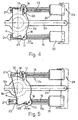
- Number 1 in Figure 1 indicates as a whole a shaping device comprising a supporting body 2 fittable to a stage lighting projector P; a first, a second, a third, and a fourth shielding member 3, 4, 5, 6; and a first and a second separating member 9, 10.
- Supporting body 2 is annular, extends about an axis A of symmetry, and comprises a first face 2a, a second face 2b ( Figures 3, 4 and 5) opposite first face 2a, and a central opening 2c.
- first face 2a supporting body 2 is fitted with a sector gear 8, which meshes with a known gear (not shown) on projector P to rotate shaping device 1 about axis A.
- Shielding members 3-6 lie in separate respective planes perpendicular to axis A of supporting body 2. More specifically, first and second shielding member 3, 4 are located on the side of face 2a of supporting body 2, and move in their respective planes substantially in a direction D1; whereas third and fourth shielding member 5, 6 are located on the side of face 2b of supporting body 2, and move in their respective planes substantially in a direction D2 perpendicular to direction D1.
- Shielding members 3-6 are semicircular or half-oval in shape, and have respective first and second coplanar connecting appendixes 11, 12 extending on opposite sides.
- First and second separating member 9, 10 comprise respective annular portions 9a, 10a, and respective connecting arms 9b, 10b fixed to supporting body 2.
- the light beam generated by projector P travels through annular portions 9a and 10a, which extend about axis A and are coaxial with supporting body 2.
- Connecting arms 9b are parallel to first direction D1; connecting arms 10b are parallel to direction D2;
- first separating member 9 is interposed between first and second shielding member 3, 4;
- second separating member 10 is interposed between third and fourth shielding member 5, 6; and each shielding member 3-6 can be superimposed completely over annular portions 9a, 10a of first and second separating member 9, 10, and can be variously tilted ( Figures 3-5).
- a first and a second guard member 27, 28, substantially similar to separating members 9, 10, are superimposed over separating members 9, 10 respectively to form gaps housing the outer shielding members, i.e. first and fourth shielding member 3, 6.
- Shaping device 1 also comprises four actuators 13a, 13b, 13c, 13d for operating respective shielding members 3-6 independently. More specifically, actuators 13a and 13b connected to shielding members 3 and 4 are located on the side of face 2a of supporting body 2; and actuators 13c and 13d are located on the side of face 2b of supporting body 2.
- Each actuator 13a-13d comprises two step motors 14; two threaded shafts 15 powered by respective motors 14; and two slides 16 fitted to respective shafts 15 by respective screw-nut screw couplings, so that rotation of shafts 15 corresponds to displacement of slides 16. Threaded shafts 15 of each actuator 13a-13d are parallel to each other, and slides 16 run along straight guides 17a, 17b defined by respective rails 21.
- Actuators 13a and 13b are connected rigidly to each other by two first guides 17a extending parallel to direction D1 between two opposite motors 14; and actuators 13c and 13d are connected rigidly to each other by two second guides 17b extending parallel to direction D2 between two opposite motors 14.
- Each first guide 17a houses a slide 16 of actuator 13a, a slide 16 of actuator 13b, and respective threaded shafts 15; and each second guide 17b houses a slide 16 of actuator 13c, a slide 16 of fourth actuator 13d, and respective threaded shafts 15.
- the slides 16 of actuators 13a and 13b, connected respectively to the first and second shielding member 3, 4 are only movable in direction D1 with respect to supporting body 2; while the slides 16 of actuators 13c and. 13d, connected respectively to the third and fourth shielding member 5, 6, are only movable in direction D2 with respect to supporting body 2.
- guides 17a, 17b have shoulders 22 resting against supporting brackets 20 of step motors 14 to simplify assembly and keep threaded shafts 15 aligned correctly; and, at respective mid-portions, guides 17a, 17b have stop devices 23 for arresting slides 16 and preventing accidental collision.
- Each slide 16 comprises an appendix 24. More specifically, appendixes 24 of the slides 16 housed in each of first and second guides 17a, 17b are positioned facing each other to keep slides 16 a predetermined minimum distance apart.
- Slides 16 have pins 18 engaging respective seats defined by holes 29 formed in connecting appendixes 11, and by slots 30 formed in connecting appendixes 12 of shielding members 3-6.
- actuators 13 are extremely precise and easy to produce, so that the risk of positioning errors of shielding members 3-6 which might impair the quality of the resulting lighting effect is greatly reduced, thus improving the reliability of shaping device 1 as a whole.
- straight guides 17 are designed to ensure correct alignment of threaded shafts 15 of step motors 14 during assembly, thus further improving the accuracy of shaping device 1.
Landscapes
- Engineering & Computer Science (AREA)
- General Engineering & Computer Science (AREA)
- Physics & Mathematics (AREA)
- General Physics & Mathematics (AREA)
- Non-Portable Lighting Devices Or Systems Thereof (AREA)
- Lighting Device Outwards From Vehicle And Optical Signal (AREA)
- Analysing Materials By The Use Of Radiation (AREA)
- Investigating Or Analyzing Materials By The Use Of Ultrasonic Waves (AREA)
- Laser Surgery Devices (AREA)
Claims (18)
- Lichtstrahlformungsvorrichtung, umfassend einen Tragkörper (2), der um eine Achse (A) verläuft und eine Öffnung (2c) für einen Lichtstrahl hat; mehrere Schirmteile (3, 4, 5, 6), die bei der Öffnung (2c) bewegbar sind, wobei die Schirmteile (3, 4, 5, 6) in separaten jeweiligen Ebenen, senkrecht zu der Achse (A), bewegbar sind;
Trennteile (9, 10), die zwischen den Schirmteilen (3, 4, 5, 6) angeordnet sind und jeweilige ringförmige Abschnitte (9a, 10a) umfassen, durch die der Lichtstrahl gelangt;
dadurch gekennzeichnet, daß jedes Schirmteil (3, 4, 5, 6) vollständig über die ringförmigen Abschnitte (9a, 10a) der Trennteile (9, 10) überlagerbar ist. - Vorrichtung nach Anspruch 1, dadurch gekennzeichnet, daß sie wenigstens ein erstes, ein zweites, ein drittes und ein viertes Schirmteil (3, 4, 5, 6) umfaßt und ein erster, ein zweiter, ein dritter und ein vierter Aktuator (13a, 13b, 13c, 13d) mit dem ersten, zweiten, dritten bzw. vierten Schirmteil (3, 4, 5, 6) verbunden ist.
- Vorrichtung nach Anspruch 2, dadurch gekennzeichnet, daß der Tragkörper (2) eine erste und eine zweite Fläche (2a, 2b) umfaßt, die einander gegenüberstehen und daß das erste und zweite Schirmteil (3, 4) und der erste und zweite Aktuator (13a, 13b) an der Seite der ersten Fläche (2a) angeordnet sind und das dritte und vierte Schirmteil (5, 6) und der dritte und vierte Aktuator (13c, 13d) an der Seite der zweiten Fläche (2b) angeordnet sind.
- Vorrichtung nach Anspruch 2 oder 3, dadurch gekennzeichnet, daß der erste und zweite Aktuator (13a, 13b) verbunden sind mit jeweils dem ersten und zweiten Schirmteil (3, 4) über Schlitten (16), die einzig in einer ersten Richtung (D1), kreuzweise zu der Achse (A) bewegbar sind und der dritte und vierte Aktuator (13c, 13d) jeweils mit dem dritten und vierten Schirmteil (5, 6) über Schlitten (16) verbunden sind, die einzig in eine zweite.Richtung (D2), kreuzweise zu der Achse (A) und zu der ersten Richtung (D1) bewegbar sind.
- Vorrichtung nach Anspruch 4, dadurch gekennzeichnet, daß die zweite Richtung (D2) senkrecht zu der ersten Richtung (D1) ist.
- Vorrichtung nach Anspruch 4 oder 5, dadurch gekennzeichnet, daß der erste und zweite Aktuator (13a, 13b) fest durch zwei erste Führungen (17a), parallel zu der ersten Richtung (D1) verbunden sind und der dritte und vierte Aktuator (13c, 13d) durch zwei zweite Führungen (17b) parallel zu der zweiten Richtung (D2) verbunden sind.
- Vorrichtung nach Anspruch 6, dadurch gekennzeichnet, daß jeder Schlitten (16) in der ersten oder zweiten Führung (17a; 17b) läuft.
- Vorrichtung nach Anspruch 7, dadurch gekennzeichnet, daß jede erste Führung (17a) einen Schlitten (16) des ersten Aktuators (13a) und einen Schlitten (16) des zweiten Aktuators (13b) aufnimmt und jede zweite Führung (17b) einen Schlitten (16) des dritten Aktuators (13c) und einen Schlitten (16) des vierten Aktuators (13d) aufnimmt.
- Vorrichtung nach Anspruch 7 oder 8, dadurch gekennzeichnet, daß der erste, zweite, dritte und vierte Aktuator (13a, 13b, 13c, 13d) jeweils zwei Motoren (14) umfassen, die jeweilige Schlitten (16) antreiben.
- Vorrichtung nach Anspruch 9, dadurch gekennzeichnet, daß jeder der Motoren (14) eine jeweilige Welle (15) umfaßt, die mit einem jeweiligen Schlitten (16) über eine Mutterschrauben-Schraubkupplung verbunden ist.
- Vorrichtung nach Anspruch 10, dadurch gekennzeichnet, daß jede der Wellen (15) in der ersten oder zweiten Führung (17a, 17b) aufgenommen ist.
- Vorrichtung nach einem der Ansprüche 8-11, dadurch gekennzeichnet, daß jeder Schlitten (16) einen Zusatz (24) umfaßt, wobei die Zusätze (24) der Schlitten (16), die in den gleichen ersten und zweiten Führungen (17a, 17b) aufgenommen sind, aufeinander zuweisend positioniert sind.
- Vorrichtung nach einem der Ansprüche 6-12, dadurch gekennzeichnet, daß die ersten und zweiten Führungen (17a, 17b) Stoppvorrichtungen (23) umfassen zum Anhalten der Schlitten (16).
- Vorrichtung nach einem der Ansprüche 2-13, dadurch gekennzeichnet, daß sie wenigstens ein erstes Trennteil (9) umfaßt, das zwischen dem ersten und zweiten Schirmteil (3, 4) angeordnet ist und ein zweites Trennteil (10), das zwischen dem dritten und vierten Schirmteil (5, 6) angeordnet ist.
- Vorrichtung nach Anspruch 14, dadurch gekennzeichnet, daß das erste Trennteil (9) einen ersten ringförmigen Abschnitt (9a) umfaßt, der über zwei erste Arme (9b) mit dem Tragkörper (2) verbunden ist und das zweite Trennteil (10) einen zweiten ringförmigen Abschnitt (10a) umfaßt, der über zwei zweite Arme (10b), die sich senkrecht zu den ersten Armen (9b) erstrecken, mit dem Tragkörper (2) verbunden ist.
- Vorrichtung nach Anspruch 5 und 15, dadurch gekennzeichnet, daß die ersten Arme (9b) des ersten Trennteils (9) parallel zu der ersten Richtung (D1) verlaufen und die zweiten Arme (10b) des zweiten Trennteils (10) parallel zu der zweiten Richtung (D2) verlaufen.
- Projektor, dadurch gekennzeichnet, daß er eine Formungsvorrichtung (1) umfaßt, wie sie in einem der Ansprüche 1-16 beansprucht ist.
- Projektor nach Anspruch 17, dadurch gekennzeichnet, daß die Formungsvorrichtung (1) derart an den Projektor (P) angebracht ist, daß sie sich um die Achse (A) dreht.
Applications Claiming Priority (3)
| Application Number | Priority Date | Filing Date | Title |
|---|---|---|---|
| ITMI20011873 | 2001-09-07 | ||
| IT2001MI001873A ITMI20011873A1 (it) | 2001-09-07 | 2001-09-07 | Dispositivo sagomatore di fasci luminosi |
| PCT/IT2002/000459 WO2003023513A1 (en) | 2001-09-07 | 2002-07-12 | Light beam shaping device |
Publications (2)
| Publication Number | Publication Date |
|---|---|
| EP1428070A1 EP1428070A1 (de) | 2004-06-16 |
| EP1428070B1 true EP1428070B1 (de) | 2006-03-08 |
Family
ID=11448340
Family Applications (1)
| Application Number | Title | Priority Date | Filing Date |
|---|---|---|---|
| EP02751619A Expired - Lifetime EP1428070B1 (de) | 2001-09-07 | 2002-07-12 | Lichstrahlformungsvorrichtung |
Country Status (4)
| Country | Link |
|---|---|
| EP (1) | EP1428070B1 (de) |
| DE (1) | DE60209740T2 (de) |
| IT (1) | ITMI20011873A1 (de) |
| WO (1) | WO2003023513A1 (de) |
Families Citing this family (8)
| Publication number | Priority date | Publication date | Assignee | Title |
|---|---|---|---|---|
| WO2007134609A1 (en) | 2006-05-23 | 2007-11-29 | Martin Professional A/S | Framing means |
| NZ547635A (en) * | 2006-06-01 | 2009-01-31 | Lantern Holdings Ltd | Lamp with coaxial rotating reflectors |
| DK201000114A (en) * | 2009-09-11 | 2011-03-12 | Martin Professional As | Light Effect System with Rotatable Light Forming Means |
| CN102483218B (zh) * | 2009-09-11 | 2015-02-11 | 马丁专业公司 | 具有可旋转束分幅的灯具 |
| IT1399478B1 (it) * | 2010-03-15 | 2013-04-19 | Clay Paky Spa | Gruppo sagomatore per sagomare un fascio luminoso e proiettore da palcoscenico comprendente detto gruppo sagomatore |
| US20120250332A1 (en) | 2011-01-31 | 2012-10-04 | Robe Lighting S.R.O. | Framing shutter system for a luminaire |
| US9989217B2 (en) | 2012-03-18 | 2018-06-05 | Robe Lighting S.R.O. | Beam framing system for an automated luminaire |
| WO2015057235A1 (en) | 2013-10-17 | 2015-04-23 | Robe Lighting, Inc. | An improved framing shutter system for a luminaire |
Family Cites Families (4)
| Publication number | Priority date | Publication date | Assignee | Title |
|---|---|---|---|---|
| US1738945A (en) * | 1928-11-01 | 1929-12-10 | Brenkert Karl | Framing shutter |
| CA1054991A (en) * | 1977-03-14 | 1979-05-22 | Joseph H. Labrum | Shutter system for stage-lighting spotlights |
| GB2265975B (en) * | 1992-03-31 | 1996-02-21 | Strand Lighting Ltd | Luminaire |
| GB2290861A (en) * | 1994-05-26 | 1996-01-10 | Strand Lighting Ltd | Luminaire |
-
2001
- 2001-09-07 IT IT2001MI001873A patent/ITMI20011873A1/it unknown
-
2002
- 2002-07-12 EP EP02751619A patent/EP1428070B1/de not_active Expired - Lifetime
- 2002-07-12 WO PCT/IT2002/000459 patent/WO2003023513A1/en not_active Ceased
- 2002-07-12 DE DE60209740T patent/DE60209740T2/de not_active Expired - Lifetime
Also Published As
| Publication number | Publication date |
|---|---|
| WO2003023513A1 (en) | 2003-03-20 |
| DE60209740D1 (de) | 2006-05-04 |
| ITMI20011873A1 (it) | 2003-03-07 |
| DE60209740T2 (de) | 2006-09-21 |
| ITMI20011873A0 (it) | 2001-09-07 |
| EP1428070A1 (de) | 2004-06-16 |
Similar Documents
| Publication | Publication Date | Title |
|---|---|---|
| US10527798B2 (en) | Fiber selector and laser apparatus | |
| WO2003023513A1 (en) | Light beam shaping device | |
| EP1167868A2 (de) | Scheinwerfer, insbesondere zum Projizieren von Lichtbündeln verschiedener Abmessungen und Farben | |
| US20110222290A1 (en) | Shaping assembly for shaping a light beam and stage light fixture comprising said shaping assembly | |
| JPH0237794A (ja) | 格子同調レーザー | |
| US10478642B2 (en) | Particle beam treatment apparatus | |
| JP2014216253A (ja) | 車両用灯具 | |
| CN108594450B (zh) | 一种可调节圆孔准直器 | |
| US20170082857A1 (en) | Display device for a motor vehicle, motor vehicle and method for operating a display device | |
| KR101527482B1 (ko) | 레이저를 이용한 미세 부품 가공 장치 | |
| KR100210506B1 (ko) | 레이저빔용 빔방향 전환셔터 | |
| US6283623B1 (en) | Method and apparatus for remote lighting | |
| JP5448586B2 (ja) | 光学素子の製造方法 | |
| CN106482033A (zh) | 照明装置和包括多个这种照明装置的透视投影仪 | |
| WO2020195023A1 (ja) | 光学キット、及び、光学装置 | |
| EP3348343B1 (de) | Laserbearbeitungskopf und ausgangskalibrierverfahren dafür | |
| CN119065143A (zh) | 一种干涉系统 | |
| JP4566622B2 (ja) | 光軸調節装置および光軸自動調節システム | |
| US6678443B2 (en) | Apparatus for slewing a light beam | |
| JPH04200892A (ja) | レーザ加工装置におけるレーザビーム伝送装置 | |
| KR102212681B1 (ko) | 카세그레인 구조의 대물렌즈의 복합 모션을 구현하기 위한 마운팅 장치 | |
| IT201700007894A1 (it) | Proiettore | |
| JP2005092149A (ja) | 光路切換スイッチ | |
| WO2025225124A1 (ja) | ケーブル連結機構 | |
| JP2006500776A (ja) | 回転運動をする波長可変空洞共振器 |
Legal Events
| Date | Code | Title | Description |
|---|---|---|---|
| PUAI | Public reference made under article 153(3) epc to a published international application that has entered the european phase |
Free format text: ORIGINAL CODE: 0009012 |
|
| 17P | Request for examination filed |
Effective date: 20040406 |
|
| AK | Designated contracting states |
Kind code of ref document: A1 Designated state(s): AT BE BG CH CY CZ DE DK EE ES FI FR GB GR IE IT LI LU MC NL PT SE SK TR |
|
| AX | Request for extension of the european patent |
Extension state: AL LT LV MK RO SI |
|
| GRAP | Despatch of communication of intention to grant a patent |
Free format text: ORIGINAL CODE: EPIDOSNIGR1 |
|
| GRAS | Grant fee paid |
Free format text: ORIGINAL CODE: EPIDOSNIGR3 |
|
| RAP1 | Party data changed (applicant data changed or rights of an application transferred) |
Owner name: CLAY PAKY S.P.A. |
|
| GRAA | (expected) grant |
Free format text: ORIGINAL CODE: 0009210 |
|
| AK | Designated contracting states |
Kind code of ref document: B1 Designated state(s): DE GB IT |
|
| REG | Reference to a national code |
Ref country code: GB Ref legal event code: FG4D |
|
| REF | Corresponds to: |
Ref document number: 60209740 Country of ref document: DE Date of ref document: 20060504 Kind code of ref document: P |
|
| PLBE | No opposition filed within time limit |
Free format text: ORIGINAL CODE: 0009261 |
|
| STAA | Information on the status of an ep patent application or granted ep patent |
Free format text: STATUS: NO OPPOSITION FILED WITHIN TIME LIMIT |
|
| 26N | No opposition filed |
Effective date: 20061211 |
|
| PGFP | Annual fee paid to national office [announced via postgrant information from national office to epo] |
Ref country code: GB Payment date: 20170719 Year of fee payment: 16 Ref country code: DE Payment date: 20170724 Year of fee payment: 16 Ref country code: IT Payment date: 20170728 Year of fee payment: 16 |
|
| REG | Reference to a national code |
Ref country code: DE Ref legal event code: R119 Ref document number: 60209740 Country of ref document: DE |
|
| GBPC | Gb: european patent ceased through non-payment of renewal fee |
Effective date: 20180712 |
|
| PG25 | Lapsed in a contracting state [announced via postgrant information from national office to epo] |
Ref country code: GB Free format text: LAPSE BECAUSE OF NON-PAYMENT OF DUE FEES Effective date: 20180712 Ref country code: DE Free format text: LAPSE BECAUSE OF NON-PAYMENT OF DUE FEES Effective date: 20190201 |
|
| PG25 | Lapsed in a contracting state [announced via postgrant information from national office to epo] |
Ref country code: IT Free format text: LAPSE BECAUSE OF NON-PAYMENT OF DUE FEES Effective date: 20180712 |