EP1427942B1 - Lenkhilfpumpe - Google Patents
Lenkhilfpumpe Download PDFInfo
- Publication number
- EP1427942B1 EP1427942B1 EP02774322A EP02774322A EP1427942B1 EP 1427942 B1 EP1427942 B1 EP 1427942B1 EP 02774322 A EP02774322 A EP 02774322A EP 02774322 A EP02774322 A EP 02774322A EP 1427942 B1 EP1427942 B1 EP 1427942B1
- Authority
- EP
- European Patent Office
- Prior art keywords
- pump
- throttle valve
- bypass
- valve
- pump according
- Prior art date
- Legal status (The legal status is an assumption and is not a legal conclusion. Google has not performed a legal analysis and makes no representation as to the accuracy of the status listed.)
- Expired - Lifetime
Links
- 230000000153 supplemental effect Effects 0.000 claims 2
- 230000001105 regulatory effect Effects 0.000 abstract description 6
- 238000009434 installation Methods 0.000 description 7
- 238000002485 combustion reaction Methods 0.000 description 4
- 238000010586 diagram Methods 0.000 description 4
- 238000000034 method Methods 0.000 description 4
- 230000006978 adaptation Effects 0.000 description 3
- 150000001875 compounds Chemical class 0.000 description 2
- 230000001419 dependent effect Effects 0.000 description 1
- 238000004134 energy conservation Methods 0.000 description 1
Images



Classifications
-
- F—MECHANICAL ENGINEERING; LIGHTING; HEATING; WEAPONS; BLASTING
- F04—POSITIVE - DISPLACEMENT MACHINES FOR LIQUIDS; PUMPS FOR LIQUIDS OR ELASTIC FLUIDS
- F04C—ROTARY-PISTON, OR OSCILLATING-PISTON, POSITIVE-DISPLACEMENT MACHINES FOR LIQUIDS; ROTARY-PISTON, OR OSCILLATING-PISTON, POSITIVE-DISPLACEMENT PUMPS
- F04C14/00—Control of, monitoring of, or safety arrangements for, machines, pumps or pumping installations
- F04C14/24—Control of, monitoring of, or safety arrangements for, machines, pumps or pumping installations characterised by using valves controlling pressure or flow rate, e.g. discharge valves or unloading valves
-
- B—PERFORMING OPERATIONS; TRANSPORTING
- B62—LAND VEHICLES FOR TRAVELLING OTHERWISE THAN ON RAILS
- B62D—MOTOR VEHICLES; TRAILERS
- B62D5/00—Power-assisted or power-driven steering
- B62D5/06—Power-assisted or power-driven steering fluid, i.e. using a pressurised fluid for most or all the force required for steering a vehicle
- B62D5/062—Details, component parts
-
- B—PERFORMING OPERATIONS; TRANSPORTING
- B62—LAND VEHICLES FOR TRAVELLING OTHERWISE THAN ON RAILS
- B62D—MOTOR VEHICLES; TRAILERS
- B62D6/00—Arrangements for automatically controlling steering depending on driving conditions sensed and responded to, e.g. control circuits
- B62D6/02—Arrangements for automatically controlling steering depending on driving conditions sensed and responded to, e.g. control circuits responsive only to vehicle speed
-
- F—MECHANICAL ENGINEERING; LIGHTING; HEATING; WEAPONS; BLASTING
- F04—POSITIVE - DISPLACEMENT MACHINES FOR LIQUIDS; PUMPS FOR LIQUIDS OR ELASTIC FLUIDS
- F04B—POSITIVE-DISPLACEMENT MACHINES FOR LIQUIDS; PUMPS
- F04B49/00—Control, e.g. of pump delivery, or pump pressure of, or safety measures for, machines, pumps, or pumping installations, not otherwise provided for, or of interest apart from, groups F04B1/00 - F04B47/00
- F04B49/22—Control, e.g. of pump delivery, or pump pressure of, or safety measures for, machines, pumps, or pumping installations, not otherwise provided for, or of interest apart from, groups F04B1/00 - F04B47/00 by means of valves
- F04B49/225—Control, e.g. of pump delivery, or pump pressure of, or safety measures for, machines, pumps, or pumping installations, not otherwise provided for, or of interest apart from, groups F04B1/00 - F04B47/00 by means of valves with throttling valves or valves varying the pump inlet opening or the outlet opening
-
- F—MECHANICAL ENGINEERING; LIGHTING; HEATING; WEAPONS; BLASTING
- F04—POSITIVE - DISPLACEMENT MACHINES FOR LIQUIDS; PUMPS FOR LIQUIDS OR ELASTIC FLUIDS
- F04B—POSITIVE-DISPLACEMENT MACHINES FOR LIQUIDS; PUMPS
- F04B2201/00—Pump parameters
- F04B2201/12—Parameters of driving or driven means
- F04B2201/1201—Rotational speed of the axis
Definitions
- the invention relates to a pump, in particular power steering pump, with a flow control valve, wherein the flow control valve includes, inter alia, a hydraulic resistance, such as a main throttle, and a control piston, wherein the main throttle may optionally be represented by a control pin and a ring diaphragm.
- a flow control valve is used to limit the volume flow in the steering with increasing pump speed, which is caused by the increasing speed of the engine from a certain volume flow and due to the unnecessary flow directly through the flow control valve internally in the pump. This means that, for example, even at idling speed, the pump is driven by the internal combustion engine at such a speed that the volume flow required for steering, for example, 10 l / min.
- flow control valves that reduce the volume flow to the steering with increasing engine speed, ie with increasing travel speed of the motor vehicle, so that a more direct steering feel at high speed.
- Such flow control valves have, for example, a control pin with a conical end, which is positioned in an annular aperture and with more open flow control valve, the main throttle, which is formed by this control pin and the annular aperture, more and more closes, so that the flow flowing to the steering flow reduces becomes.
- further possibilities of influencing the volume flow are no longer possible with such flow control devices, so that practically the volume flow delivered to the steering is influenced only by the pump speed.
- a pump in particular power steering pump, with a flow control valve, wherein the flow control valve includes, inter alia, a hydraulic resistance, such as a main throttle, and a control piston, wherein the main throttle may optionally be represented by a control pin and a ring diaphragm, wherein parallel to Main throttle is arranged an electrically adjustable bypass throttle.
- the volume flow from the pump to the consumer, such as the steering in addition electrically influenced.
- the bypass throttle is acted upon by the same differential pressure as the main throttle.
- An embodiment of the pump according to the invention is characterized in that the bypass throttle reduces the flow rate from the pump to the consumer with increasing drive current.
- a further preferred embodiment increases the flow rate from the pump to the consumer with increasing drive current of the bypass throttle.
- an embodiment in which the electrically adjustable bypass throttle is adaptable to standard pumps, so that flexible mounting positions of the bypass throttle are possible, regardless of where in the pump arranged on the flow control valve main throttle is realized.
- This has the particular advantage that, depending on the installation situation of an existing pump in a specific engine compartment, the installation location of the additional bypass throttle can be adapted to these engine compartment conditions without negatively influencing the main throttle located in the flow control valve, and thus the function of the flow control valve.
- An embodiment of the pump according to the invention is characterized in that the main throttle of the standard pump ensures the basic delivery of the volume flow for the steering, especially in the case of fail-safe, that is, for example, if the electrical supply fails, and that the electrically adjustable Bypass throttle for additional variation of the flow rate to the consumer depending on various parameters is used.
- the parameters which are to influence the electrically adjustable bypass throttle may be parameters such as driving speed, engine speed, cornering behavior, braking behavior, driving stability, steering angle, steering angle speed, wheel speeds or wheel slip.
- a pump according to the invention is characterized in that energy savings can be realized by using the additional electric bypass throttle for existing main throttle on standard pumps. Furthermore, according to the invention, a pump can be displayed, which enables the use of vehicles with active steering systems by using the additional electric bypass throttle on standard pumps.
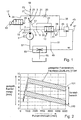
- FIG. 1 shows a hydraulic circuit diagram of a pump according to the invention.
- FIG. 2 shows the characteristic range of a pump according to the invention.
- FIG. 3 shows a structural design of a pump according to the invention.
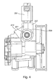
- Figure 4 shows a further structural design.
- Figure 5 also shows another embodiment.
- FIG. 6 shows a schematic diagram for a method for determining the magnetic current control of the bypass throttle.
- FIG. 1 shows a pump arrangement according to the invention in the form of a hydraulic circuit diagram.
- a pump unit 1 is driven via a drive shaft 3 by a drive, not further shown here, such as a pulley, by an internal combustion engine. With increasing speed, the pump 1 conveys a volume flow into the connection point 5.
- a compound 7 From the connection point 5 leads a compound 7 to a variable main throttle 9, which is represented by a throttle symbol with an arrow, another connection 11 leads to a control piston of a control valve 13, and a third connection 15 leads to an electrically adjustable bypass throttle 17.
- the line 11 leads to a connection point 19, from which a line 21 leads to the control piston of the control valve 13, while a control line 23 acts on the left side of the control piston.
- connection point 5 in the compounds 15, 7, 11 and 21.
- a volume flow can flow by means of connection 25 to the connection point 27, in which also a connection 29 from the electrically adjustable bypass throttle 17 opens.
- connection point 27 a connecting line 31 to a throttle 33 and via a connection 35 on to a connection point 37, in which a control line 39 to the right side of the control piston is effective.
- a control line 39 to the right side of the control piston acts on the right side of the control piston of the control valve 13, a spring 41.
- From the connection point 37 is a control line 43 continues to a pressure relief pilot 45 and via a line 47 to a connection point 49, in which the outflow line 51 of the control valve 13 opens.
- the function of the pump device is the following:
- a volume flow via the main throttle 9 increases, which flows to the consumer 59, such as a power steering system.
- the pressure difference P1 minus P2 at the main throttle increases.
- the pressure difference P1 minus P2 which acts together with the spring 41 on the control piston of the control valve 13, is finally so large that the pressure P1 can adjust the control piston against the pressure P2 and the spring 41 to the right, so that a flow over the Regulating piston can flow and in turn the intake region 57 of the pump 1 is supplied.
- the variable main throttle 9 is further closed in the event of an increasing opening movement of the piston 13 so that as the pump speed increases, a volume flow flowing to the consumer is reduced.
- the volume flow flowing to the consumer 59 is predetermined by the mechanical conditions of the control valve 13 and the adjustable main throttle 9 and can not be changed further.
- the invention uses parallel to the main throttle 9, the electrically adjustable bypass throttle 17, which can push the piston of the bypass throttle continuously with increasing drive current to an electromagnet 63 against a spring force 65 and so that an additional volume flow into the node 27 and thus to the consumer 59 allows.
- a volume flow map can be realized.
- FIG. 2 shows the bandwidth of such a volume flow characteristic map.
- the pump speed in rpm here from 0 to 6000 revolutions
- the regulated flow rate to the consumer 59 in l / min here between 0 and 10 l / min, applied.
- a flow characteristic curve 100 can be seen, which at about 600 U / min has an average flow rate of 4.5 l / min, which increases with increasing speed up to 6000 U / min to a mean flow rate of 2 l / min lowers.
- This volumetric flow band corresponds to the volume flow which is set by the control piston of the control valve 13 and the variable main throttle 9, wherein the bandwidth should include all additional tolerances in the system.
- the procedure may be such that the variable main throttle 9 ensures the basic delivery rate of the pump.
- the control pin which is mechanically connected to the control piston of the control valve 13, as before various speed-dependent characteristics of the basic flow rate can be realized.
- the electrically adjustable bypass throttle 17 which is connected in parallel to the main throttle 9 and is acted upon by the same differential pressure P1 minus P2, the delivery rate of the pump can be additionally varied.
- the bypass throttle 17 can reduce or increase the delivery rate of the pump 1 to the consumer 59 with increasing drive current for the magnet 63.
- FIG 3 the structural adaptation of such a variable main throttle is shown on a standard pump housing.
- the electrically operable bypass throttle valve 201 is attached via a connecting piece 203 to a cover 205 of a standard power steering pump.
- the cover 205 closes a pump housing 207, in which in a valve housing 209 the previously existing flow control valve and the variable main throttle are arranged, which are not visible here.
- the volume flow to the consumer is made by a connection 211 on the pump, and the return flow from the consumer and the tank via the port 213.
- shown here pump can be changed by changing the lid 205 or the connection part 203 a number of variations of the position of the electric valve 201 can be achieved without changing the other structural conditions of the pump or even the vehicle.
- FIG. 4 shows the adaptation of such an electric bypass throttle to another standard pump.
- the electric bypass throttle valve 201 is mounted here on the pump housing 207 above the flow control valve housing 209, so that here results in a vertical mounting according to the installation conditions of this pump.
- the pressure connection to the consumer 211 and the suction connection of the pump 213 are arranged in this pump in other positions, so that according to these circumstances and the installation space in the vehicle here a vacant position for positioning the bypass throttle can be found in other ways.
- FIG. 5 shows the same type of pump as in FIG. 4 with an axial attachment of the electric bypass throttle 201.
- the space behind the pump for adapting the solenoid valve 201 can be used here if there is no space in the areas around the valve housing 209 and in the intake area 213 or in the pressure output area 211. It can already be seen from these illustrations that the additional bypass throttle with flexible mounting positions enables simple adaptation to standard pumps.
- FIG. 6 shows a schematic diagram for a method for determining the magnetic current control of the bypass throttle 201.
- the magnetic current is determined by an electronic computer device on the basis of a plurality of input variables, and a magnetic current is output accordingly.
- the driving speeds 301, the steering angle speed 303, the rotational speed 305 of the internal combustion engine and the steering angle 307 are used as input variables for the algorithm for determining the magnet current.
- the steering angle speed 303 is generated via a functional unit as a first input variable for a map 309.
- the vehicle speed 301 is used as the second input variable for the characteristic map 309.
- a characteristic valve opening value as a function of the vehicle speed 301 and the steering angle speed 303 is mapped in the map 309.
- the map 309 in turn serves as a first input for a second map 311, which processes the engine speed 305 as a second input variable.
- the second characteristic map 311 in turn serves as the first input variable for a functional unit 315, for which a characteristic 313 serves as the second input variable.
- the characteristic curve 313 is formed from the steering angle signal 307 and represents a valve opening value as a function of the steering angle 307.
- the output of the functional unit 315 is input to a functional unit 317 in which the solenoid current characteristic for the solenoid current 319 of the bypass reactor 201 is generated as a function of the Ventifö Maschinenschens learners.
- the solenoid current 319 is then provided to the solenoid of the bypass reactor 201.
Landscapes
- Engineering & Computer Science (AREA)
- Mechanical Engineering (AREA)
- Combustion & Propulsion (AREA)
- General Engineering & Computer Science (AREA)
- Chemical & Material Sciences (AREA)
- Transportation (AREA)
- Fluid Mechanics (AREA)
- Physics & Mathematics (AREA)
- Power Steering Mechanism (AREA)
- Steering Control In Accordance With Driving Conditions (AREA)
- Rotary Pumps (AREA)
- Details And Applications Of Rotary Liquid Pumps (AREA)
- Magnetically Actuated Valves (AREA)
Description
- Die Erfindung betrifft eine Pumpe, insbesondere Lenkhilfpumpe, mit einem Stromregelventil, wobei das Stromregelventil unter anderem einen hydraulischen Widerstand, wie eine Hauptdrossel, und einen Regelkolben enthält, wobei die Hauptdrossel gegebenenfalls durch einen Regelstift und eine Ringblende dargestellt sein kann. Derartige Pumpen sind bekannt. So wird bei Lenkhilfpumpen generell ein Stromregelventil verwendet, um bei steigender Pumpendrehzahl, die durch die steigende Drehzahl des Verbrennungsmotors verursacht wird, ab einem bestimmten Volumenstrom den Volumenstrom in die Lenkung zu begrenzen und den überflüssigen Volumenstrom direkt über das Stromregelventil wieder intern in der Pumpe zurückzuführen. Das bedeutet, dass zum Beispiel schon bei Leerlaufdrehzahl die Pumpe durch den Verbrennungsmotor mit einer derartigen Drehzahl angetrieben wird, dass der für die Lenkung benötigte Volumenstrom von zum Beispiel 10 l/min. zur Verfügung steht. Mit zunehmender Fahrgeschwindigkeit und damit mit zunehmender Drehzahl des Verbrennungsmotors wird dann der weiter ansteigende Pumpenvolumenstrom über das Stromregelventil aufgeteilt in den zur Lenkung fließenden Volumenstrom von ca. 10 l/min. und in einen zusätzlichen Abregelvolumenstrom, der in den Ansaugbereich der Pumpe zurückgeführt wird. Bekannt sind auch Stromregelventile, die mit zunehmender Verbrennungsmotordrehzahl, das heißt mit zunehmender Fahrgeschwindigkeit des Kraftfahrzeuges, den Volumenstrom zur Lenkung reduzieren, damit ein direkteres Lenkgefühl bei hoher Geschwindigkeit entsteht. Derartige Stromregelventile besitzen zum Beispiel einen Regelstift mit einem konischen Ende, der in einer Ringblende positioniert ist und bei sich weiter öffnendem Stromregelventil die Hauptdrossel, die durch diesen Regelstift und die Ringblende gebildet wird, mehr und mehr verschließt, so dass der zur Lenkung fließende Volumenstrom reduziert wird. Weitere Einflussmöglichkeiten auf den Volumenstrom sind bei derartigen Stromregeleinrichtungen aber nicht mehr möglich, so dass praktisch der an die Lenkung abgegebene Volumenstrom nur durch die Pumpendrehzahl beeinflusst wird.
- Es sind auch Lenkhilfpumpen mit Stromregelventilen bekannt, bei denen die Hauptdrossel über einen Elektromagneten verstellt werden kann. Das bedeutet, dass im Bereich des Stromregelventils die Anordnung des Elektromagneten durch die Position der Hauptdrossel vorgegeben ist und damit die möglichen Einbaulagen des elektromagnetischen Ventils beschränkt sind. Auch ist der Einbauraum einer derartigen Pumpe größer und damit der Einbau in verschiedenen Motorräumen schwieriger. US 5111660 offenbart eine derartige Pumpe.
- Es ist deshalb Aufgabe der Erfindung, eine Pumpe darzustellen, die diese Nachteile nicht aufweist. Die Aufgabe wird gelöst durch eine Pumpe, insbesondere Lenkhilfpumpe, mit einem Stromregelventil, wobei das Stromregelventil unter anderem einen hydraulischen Widerstand, wie eine Hauptdrossel, und einen Regelkolben enthält, wobei die Hauptdrossel gegebenenfalls durch einen Regelstift und eine Ringblende dargestellt sein kann, wobei parallel zur Hauptdrossel eine elektrisch verstellbare Bypassdrossel angeordnet ist. Erfindungsgemäß ist dadurch der Volumenstrom von der Pumpe zum Verbraucher, wie der Lenkung, zusätzlich elektrisch beeinflussbar. Vorzugsweise wird die Bypassdrossel von demselben Differenzdruck beaufschlagt wie die Hauptdrossel.
- Eine erfindungsgemäße Ausführungsform der Pumpe zeichnet sich dadurch aus, dass die Bypassdrossel mit zunehmendem Ansteuerstrom die Fördermenge von der Pumpe zum Verbraucher reduziert. Eine weitere bevorzugte Ausführungsform erhöht mit zunehmendem Ansteuerstrom der Bypassdrossel die Fördermenge von der Pumpe zum Verbraucher.
- Es wird nach Anspruch 1 eine Ausführungsform bevorzugt, bei welcher die elektrisch verstellbare Bypassdrossel an serienmäßigen Pumpen adaptierbar ist, so dass flexible Einbaulagen der Bypassdrossel möglich sind, unabhängig davon, wo in der Pumpe die am Stromregelventil angeordnete Hauptdrossel realisiert ist. Das hat besonders den Vorteil, dass je nach Einbausituation einer vorhandenen Pumpe in einem bestimmten Motorraum der Einbauort der zusätzlichen Bypassdrossel diesen Motorraumbedingungen angepasst werden kann, ohne die im Stromregelventil befindliche Hauptdrossel, und damit die Funktion des Stromregelventils, negativ zu beeinflussen.
- Eine erfindungsgemäße Ausführungsform der Pumpe zeichnet sich dadurch aus, dass die Hauptdrossel der serienmäßigen Pumpe die Grundfördermenge des Volumenstromes für die Lenkung sicherstellt, vor allem im Fail-Safe-Fall, das heißt, wenn zum Beispiel die elektrische Versorgung ausfällt, und dass die elektrisch verstellbare Bypassdrossel zur zusätzlichen Variation der Fördermenge zum Verbraucher in Abhängigkeit verschiedener Parameter dient. Erfindungsgemäß können dabei die Parameter, die Einfluss auf die elektrisch verstellbare Bypassdrossel nehmen sollen, Parameter wie Fahrgeschwindigkeit, Motordrehzahl, Kurvenverhalten, Bremsverhalten, Fahrstabilität, Lenkwinkel, Lenkwinkelgeschwindigkeit, Raddrehzahlen oder Radschlupf sein.
- Auch zeichnet sich eine erfindungsgemäße Pumpe dadurch aus, dass durch Verwendung der zusätzlichen elektrischen Bypassdrossel zur vorhandenen Hauptdrossel an serienmäßigen Pumpen Energieeinsparungen realisierbar sind. Weiterhin ist erfindungsgemäß eine Pumpe darstellbar, welche durch Verwendung der zusätzlichen elektrischen Bypassdrossel an serienmäßigen Pumpen die Verwendung für Fahrzeuge mit aktiven Lenksystemen ermöglicht.
- Die Erfindung wird nun anhand der Figuren erläutert.
- Figur 1 zeigt einen Hydraulikschaltplan einer erfindungsgemäßen Pumpe.
- Figur 2 zeigt den Kennlinienbereich einer erfindungsgemäßen Pumpe.
- Figur 3zeigt eine konstruktive Ausführung einer erfindungsgemäßen Pumpe.
- Figur 4zeigt eine weitere konstruktive Ausführung.
- Figur 5zeigt ebenfalls eine weitere Ausführung.
- Figur 6zeigt ein schematisches Diagramm für ein Verfahren zur Ermittlung der Magnetstromansteuerung der Bypassdrossel.
- In Figur 1 wird eine erfindungsgemäße Pumpenanordnung in Form eines Hydraulikschaltplanes dargestellt. Eine Pumpeneinheit 1 wird über eine Antriebswelle 3 von einem hier weiter nicht dargestellten Antrieb, wie zum Beispiel einer Riemenscheibe, von einem Verbrennungsmotor angetrieben. Mit zunehmender Drehzahl fördert die Pumpe 1 einen Volumenstrom in den Verbindungspunkt 5. Vom Verbindungspunkt 5 führt eine Verbindung 7 zu einer variablen Hauptdrossel 9, die durch ein Drosselsymbol mit einem Pfeil dargestellt ist, eine weitere Verbindung 11 führt zu einem Regelkolben eines Regelventils 13, und eine dritte Verbindung 15 führt zu einer elektrisch verstellbaren Bypassdrossel 17. Die Leitung 11 führt zu einem Verbindungspunkt 19, von dem eine Leitung 21 zum Regelkolben des Regelventils 13 führt, während eine Steuerleitung 23 auf die linke Seite des Regelkolbens wirkt. In der Steuerleitung 23 wirkt der am Pumpenausgang anstehende Druck P1, der über den Verbindungspunkt 5 in den Verbindungen 15, 7, 11 und 21 ebenfalls wirksam ist. Über die Hauptdrossel 9 kann ein Volumenstrom mittels Verbindung 25 zum Verbindungspunkt 27 strömen, in welchem auch eine Verbindung 29 von der elektrisch verstellbaren Bypassdrossel 17 mündet. Ferner führt vom Knotenpunkt 27 eine Verbindungsleitung 31 zu einer Drossel 33 und über eine Verbindung 35 weiter zu einem Verbindungspunkt 37, in welchem eine Steuerleitung 39 auf die rechte Seite des Regelkolbens wirksam wird. Ferner wirkt auf die rechte Seite des Regelkolbens des Regelventils 13 eine Feder 41. Vom Verbindungspunkt 37 geht eine Steuerleitung 43 weiter zu einem Druckbegrenzungspiloten 45 und über eine Leitung 47 zu einem Verbindungspunkt 49, in welchem die Abflussleitung 51 des Regelventils 13 einmündet. Über eine Injektoreinrichtung 53, in der die vom Stromregelventil und Druckbegrenzungsventil fließenden Ölströme aus einer Tankleitung 55 Öl mitreißen können, fließt das vom Stromregelventil 13 und/oder vom Druckpiloten 45 abströmende Öl über die Pumpenansaugleitung 57 wieder der Pumpeneinheit 1 zu.
- Mit zunehmender Drehzahl der Pumpeneinheit 1 nimmt ein Volumenstrom über die Hauptdrossel 9 zu, welcher zum Verbraucher 59, wie zum Beispiel einer Servolenkung, strömt. Mit zunehmendem Volumenstrom über die Hauptdrossel 9 nimmt die Druckdifferenz P1 minus P2 an der Hauptdrossel zu. Die Druckdifferenz P1 minus P2, die zusammen mit der Feder 41 auf den Regelkolben des Regelventils 13 wirkt, wird schließlich so groß, dass der Druck P1 den Regelkolben gegen den Druck P2 und die Feder 41 nach rechts verstellen kann, so dass ein Volumenstrom über den Regelkolben abfließen kann und wiederum dem Ansaugbereich 57 der Pumpe 1 zugeführt wird. Da in dieser Darstellung der Regelkolben 13 über eine mechanische Verbindung 61 mit der variablen Hauptdrossel 9 verbunden ist, wird bei einer zunehmenden Öffnungsbewegung des Kolbens 13 die variable Hauptdrossel 9 weiter geschlossen, so dass mit zunehmender Pumpendrehzahl ein zum Verbraucher fließender Volumenstrom reduziert wird. Damit ist der zum Verbraucher 59 strömende Volumenstrom durch die mechanischen Gegebenheiten des Regelventils 13 und der verstellbaren Hauptdrossel 9 vorgegeben und nicht weiter veränderbar. Um nun zusätzliche Parameter auf die Höhe des Volumenstromes zum Verbraucher 59 wirksam werden zu lassen, nutzt die Erfindung parallel zur Hauptdrossel 9 die elektrisch verstellbare Bypassdrossel 17, welche mit zunehmendem Ansteuerstrom auf einen Elektromagneten 63 gegen eine Federkraft 65 den Kolben der Bypassdrossel stufenlos aufschieben kann und damit einen zusätzlichen Volumenstrom in den Knotenpunkt 27 und damit zum Verbraucher 59 ermöglicht. Damit ist unabhängig von den mechanischen Gegebenheiten des Regelkolbens des Regelventils 13 und der Hauptdrossel 9 ein Volumenstromkennfeld realisierbar.
- Figur 2 zeigt die Bandbreite eines derartigen Volumenstromkennfeldes. Über der Pumpendrehzahl in U/min, hier von 0 bis 6000 Umdrehungen, ist die geregelte Fördermenge zum Verbraucher 59 in l/min, hier zwischen 0 und 10 l/min, aufgetragen. Dabei ist ein Förderstrom-Kennlinienband 100 zu erkennen, welches bei etwa 600 U/min einen mittleren Volumenstrom von 4,5 l/min aufweist, der sich mit zunehmender Drehzahl bis hin zu 6000 U/min auf einen mittleren Volumenstrom von 2 l/min absenkt. Dieses Volumenstromband entspricht zum Beispiel dem Volumenstrom, der durch den Regelkolben des Regelventils 13 und die variable Hauptdrossel 9 eingestellt wird, wobei die Bandbreite alle zusätzlichen Toleranzen im System beinhalten soll. Mit der elektrisch verstellbaren Bypassdrossel 17 aus Figur 1 ist durch Öffnen der Bypassdrossel ein zusätzlicher Volumenstrom zum Verbraucher darstellbar, der bis hin zur maximalen Öffnung der Bypassdrossel 17 zu dem Kennlinienband 101 in der Figur 2 führt. Somit sind dabei bei etwa 1000 U/min 8 1/min realisierbar, welche durch die variable Hauptdrossel 9 bei 6000 U/min auf etwa 6,5 l/min abgesenkt werden. Durch die stufenlose Verstellung der variablen Hauptdrossel 17 sind alle Kennlinien zwischen der Kennlinie 100 und 101 realisierbar. So kann zum Beispiel für das Parkieren ein großer Volumenstrom bereitgestellt werden, der bei hoher Fahrgeschwindigkeit abgesenkt wird, um das Gefühl der Lenkkräfte am Lenkrad direkter darzustellen. Genauso kann aber entsprechend anderen Fahrzeugparametern wie Kurvengeschwindigkeit, Bremsverhalten, Schlupf der Räder usw. eine entsprechende Förderstrom-Kennlinie für die Lenkung eingestellt werden. Ebenso ist es möglich, durch die variable Hauptdrossel den zunächst zum Parkieren benötigten großen Volumenstrom relativ schnell auf einen Minimal-Volumenstrom abzusenken und damit zur Energieeinsparung beizutragen.
- Prinzipiell kann dabei die Vorgehensweise so sein, dass die variable Hauptdrossel 9 die Grundfördermenge der Pumpe sicherstellt. Durch den Regelstift, der mit dem Regelkolben des Regelventils 13 mechanisch verbunden ist, können wie bisher verschiedene drehzahlabhängige Kennlinien der Grundfördermenge realisiert werden. Durch die elektrisch verstellbare Bypassdrossel 17, die parallel zu der Hauptdrossel 9 geschaltet ist und von dem selben Differenzdruck P1 minus P2 beaufschlagt wird, kann die Fördermenge der Pumpe zusätzlich variiert werden. Je nach konstruktiver Auslegung kann die Bypassdrossel 17 mit zunehmendem Ansteuerstrom für den Magneten 63 die Fördermenge der Pumpe 1 zum Verbraucher 59 reduzieren oder erhöhen. Für das Fail-Safe-Verhalten einer derartigen Pumpeneinrichtung ist es daher auch von Vorteil, dass beim Ausfall der elektrischen Versorgung die Funktion der mechanischen Hauptdrossel 9 erhalten bleibt, was bei einer reinen elektrisch verstellbaren Hauptdrossel schwieriger zu realisieren wäre.
- In Figur 3 ist die konstruktive Adaption einer derartigen variablen Hauptdrossel an einem serienmäßigen Pumpengehäuse dargestellt. Das elektrisch betätigbare Bypass-Drosselventil 201 ist über ein Anschlussstück 203 an einem Deckel 205 einer serienmäßigen Lenkhilfpumpe befestigt. Der Deckel 205 verschließt ein Pumpengehäuse 207, in welchem in einem Ventilgehäuse 209 das bisher vorhandene Stromregelventil und die variable Hauptdrossel angeordnet sind, welche hier nicht sichtbar sind. Der Volumenstromzufluss zum Verbraucher wird durch einen Anschluss 211 an der Pumpe hergestellt, und der Rückfluss vom Verbraucher und vom Tank erfolgt über den Anschluss 213. Je nach baulichen Gegebenheiten im Motorraum der bisher verwendeten, hier dargestellten Pumpe kann über eine Änderung des Deckels 205 bzw. des Anschlussteils 203 eine Reihe von Variationen der Position des elektrischen Ventils 201 erreicht werden, ohne die anderen baulichen Gegebenheiten der Pumpe oder gar des Fahrzeugs zu verändern.
- In Figur 4 ist die Adaption einer derartigen elektrischen Bypassdrossel auf einer anderen serienmäßigen Pumpe dargestellt. Das elektrische Bypass-Drosselventil 201 ist hier auf dem Pumpengehäuse 207 oberhalb des Stromregelventilgehäuses 209 angebracht, so dass sich hier ein vertikaler Anbau entsprechend den Einbaugegebenheiten dieser Pumpe ergibt. Der Druckanschluss zum Verbraucher 211 und der Sauganschluss der Pumpe 213 sind bei dieser Pumpe in anderen Positionen angeordnet, so dass entsprechend diesen Gegebenheiten und dem Einbauraum im Fahrzeug hier eine freie Stelle zur Positionierung der Bypassdrossel in anderer Weise gefunden werden kann.
- In Figur 5 ist der gleiche Pumpentyp wie in Figur 4 mit einem axialen Anbau der elektrischen Bypassdrossel 201 dargestellt. Je nach Gegebenheiten am Einbauort der Pumpe im Motorraum kann hier der Platz hinter der Pumpe zur Adaption des Magnetventils 201 benutzt werden, wenn in den Bereichen um das Ventilgehäuse 209 und im Ansaugbereich 213 oder im Druckausgangsbereich 211 kein Platz vorhanden ist. Man erkennt schon an diesen Darstellungen, dass die zusätzliche Bypassdrossel mit flexiblen Einbaulagen eine einfache Adaption an serienmäßigen Pumpen ermöglicht.
- Figur 6 zeigt ein schematisches Diagramm für ein Verfahren zur Ermittlung der Magnetstromansteuerung der Bypassdrossel 201. Dabei wird der Magnetstrom aufgrund mehrerer Eingangsgrößen durch eine elektronische Rechnereinrichtung ermittelt und entsprechend ein Magnetstrom ausgegeben. Als Eingangsgrößen für den Algorithmus zur Ermittlung des Magnetstromes dienen die Fahrgeschwindigkeit 301, die Lenkwinkelgeschwindigkeit 303, die Drehzahl 305 des Verbrennungsmotors und der Lenkwinkel 307. Die Lenkwinkelgeschwindigkeit 303 wird über eine Funktionseinheit als erste Eingangsgröße für ein Kennfeld 309 erzeugt. Als zweite Eingangsgröße für das Kennfeld 309 dient die Fahrzeuggeschwindigkeit 301. Im Kennfeld 309 wird somit ein Ventilöffnungswert als Funktion von Fahrzeuggeschwindigkeit 301 und Lenkwinkelgeschwindigkeit 303 abgebildet. Das Kennfeld 309 dient wiederum als erste Eingangsgröße für ein zweites Kennfeld 311, welches als zweite Eingangsgröße die Motordrehzahl 305 verarbeitet. Im Kennfeld 311 wird also ein Ventilöffnungswert als Funktion des Kennfeldes 309 und der Verbrennungsmotordrehzahl 305 abgebildet. Das zweite Kennfeld 311 wiederum dient als erste Eingangsgröße für eine Funktionseinheit 315, für welche als zweite Eingangsgröße eine Kennlinie 313 dient. Die Kennlinie 313 wird aus dem Lenkwinkelsignal 307 gebildet und stellt einen Ventilöffnungswert als Funktion des Lenkwinkels 307 dar. Die Ausgangsgröße der Funktionseinheit 315 ist Eingangsgröße für eine Funktionseinheit 317, in welcher die Magnetstromkennlinie für den Magnetstrom 319 der Bypassdrossel 201 als Funktion des Ventiföffnungswertes erzeugt wird. Der Magnetstrom 319 wird dann dem Elektromagneten der Bypassdrossel 201 zur Verfügung gestellt.
Claims (9)
- Pumpe, insbesondere Lenkhilfpumpe, mit einem Stromregelventil (13), wobei das Stromregelventil (13) unter anderem einen hydraulischen Widerstand, wie eine Hauptdrossel (9), und einen Regelkolben enthält, wobei die Hauptdrossel (9) gegebenenfalls durch einen Regelstift und eine Ringblende dargestellt sein kann, wobei parallel zur Hauptdrossel (9) eine elektrisch verstellbare Bypassdrossel (17) angeordnet ist, dadurch gekennzeichnet, dass die elektrisch verstellbare Bypassdrossel (17) an serienmäßigen Pumpen über ein in seiner Position variabel gestaltbares Anschlussstück (203) an einem Deckel (205) adaptiert ist,
oder auf dem Pumpengehäuse (207) vertikal oberhalb des Stromregelventilgehäuses (209) adaptiert ist,
oder an der Rückseite des Pumpengehäuses (207) axial hinter dem Stromregelventilgehäuse (209) adaptiert ist. - Pumpe nach Anspruch 1, dadurch gekennzeichnet, dass der Volumenstrom von der Pumpe zum Verbraucher (59), wie Lenkung, zusätzlich elektrisch beeinflussbar ist.
- Pumpe nach Anspruch 2, dadurch gekennzeichnet, dass die Bypassdrossel (17) von demselben Differenzdruck beaufschlagt wird wie die Hauptdrossel (9).
- Pumpe nach Anspruch 3, dadurch gekennzeichnet, dass die Bypassdrossel (17) mit zunehmendem Ansteuerstrom die Fördermenge von der Pumpe zum Verbraucher (59) reduziert.
- Pumpe nach Anspruch 3, dadurch gekennzeichnet, dass die Bypassdrossel (17) mit zunehmendem Ansteuerstrom die Fördermenge von der Pumpe zum Verbraucher (59) erhöht.
- Pumpe nach einem der vorhergehenden Ansprüche, dadurch gekennzeichnet, dass die Hauptdrossel (9) der serienmäßigen Pumpen die Grundfördermenge des Volumenstromes für die Lenkung (59) sicherstellt, vor allem im Fail-Safe-Fall, und die elektrisch verstellbare Bypassdrossel (17) zur zusätzlichen Variation der Fördermenge zum Verbraucher (59) in Abhängigkeit verschiedener Parameter dient.
- Pumpe nach einem der vorhergehenden Ansprüche, dadurch gekennzeichnet, dass die Parameter für die elektrisch verstellbare Bypassdrossel (17) Parameter wie Fahrgeschwindigkeit (301), Motordrehzahl (305), Kurvenverhalten, Bremsverhalten, Fahrstabilität, Lenkwinkel (307), Lenkwinkelgeschwindigkeit (303), Raddrehzahlen und/ oder Radschlupf sein können.
- Pumpe nach einem der vorhergehenden Ansprüche, dadurch gekennzeichnet, dass durch Verwendung der zusätzlichen elektrischen Bypassdrossel (17) an serienmäßigen Pumpen Energieeinsparungen realisierbar sind.
- Pumpe nach einem der vorhergehenden Ansprüche, dadurch gekennzeichnet, dass durch Verwendung der zusätzlichen elektrischen Bypassdrossel (17) an serienmäßigen Pumpen aktive Lenksysteme realisierbar sind.
Applications Claiming Priority (5)
| Application Number | Priority Date | Filing Date | Title |
|---|---|---|---|
| DE10145224 | 2001-09-13 | ||
| DE10145224 | 2001-09-13 | ||
| DE10157145 | 2001-11-22 | ||
| DE10157145 | 2001-11-22 | ||
| PCT/DE2002/003362 WO2003023227A1 (de) | 2001-09-13 | 2002-09-11 | Lenkhilpumpe |
Publications (2)
| Publication Number | Publication Date |
|---|---|
| EP1427942A1 EP1427942A1 (de) | 2004-06-16 |
| EP1427942B1 true EP1427942B1 (de) | 2007-06-06 |
Family
ID=26010127
Family Applications (1)
| Application Number | Title | Priority Date | Filing Date |
|---|---|---|---|
| EP02774322A Expired - Lifetime EP1427942B1 (de) | 2001-09-13 | 2002-09-11 | Lenkhilfpumpe |
Country Status (9)
| Country | Link |
|---|---|
| US (1) | US20040247469A1 (de) |
| EP (1) | EP1427942B1 (de) |
| JP (1) | JP2005502001A (de) |
| AT (1) | ATE364137T1 (de) |
| DE (3) | DE10294124D2 (de) |
| ES (1) | ES2286288T3 (de) |
| FR (1) | FR2829534B1 (de) |
| IT (1) | ITMI20021945A1 (de) |
| WO (1) | WO2003023227A1 (de) |
Families Citing this family (7)
| Publication number | Priority date | Publication date | Assignee | Title |
|---|---|---|---|---|
| JP3915718B2 (ja) * | 2003-03-11 | 2007-05-16 | 株式会社デンソー | 燃料供給ポンプ |
| DE10311444A1 (de) * | 2003-03-15 | 2004-09-23 | Daimlerchrysler Ag | Verfahren zum Betreiben einer Servolenkeinrichtung und Vorrichtung zur Durchführung des Verfahrens |
| JP4036197B2 (ja) * | 2003-04-03 | 2008-01-23 | 株式会社デンソー | 燃料供給ポンプ |
| JP2005112280A (ja) * | 2003-10-10 | 2005-04-28 | Kayaba Ind Co Ltd | パワーステアリング装置 |
| US7302798B2 (en) | 2004-07-07 | 2007-12-04 | Toyoda Koki Kabushiki Kaisha | Hydraulic system, reservoir and pump suction enhancer for motor vehicle |
| DE102007036502A1 (de) * | 2007-08-01 | 2009-02-05 | Thyssenkrupp Presta Ag | Druckleitung zur fluidischen Verbindung einer Pumpe zu einem hydraulischen Stellaggregat in einem Kraftfahrzeug |
| US10378536B2 (en) | 2014-06-13 | 2019-08-13 | Clark Equipment Company | Air compressor discharge system |
Family Cites Families (3)
| Publication number | Priority date | Publication date | Assignee | Title |
|---|---|---|---|---|
| JPS5818586A (ja) * | 1981-07-27 | 1983-02-03 | Jidosha Kiki Co Ltd | 流量制御弁 |
| US4691797A (en) * | 1986-07-10 | 1987-09-08 | Trw Inc. | Fluid flow control apparatus for a power steering system |
| US5111660A (en) * | 1991-03-11 | 1992-05-12 | Ford Motor Company | Parallel flow electronically variable orifice for variable assist power steering system |
-
2002
- 2002-09-11 US US10/489,566 patent/US20040247469A1/en not_active Abandoned
- 2002-09-11 JP JP2003527268A patent/JP2005502001A/ja active Pending
- 2002-09-11 DE DE10294124T patent/DE10294124D2/de not_active Expired - Fee Related
- 2002-09-11 ES ES02774322T patent/ES2286288T3/es not_active Expired - Lifetime
- 2002-09-11 AT AT02774322T patent/ATE364137T1/de not_active IP Right Cessation
- 2002-09-11 DE DE10242040A patent/DE10242040A1/de not_active Ceased
- 2002-09-11 DE DE50210285T patent/DE50210285D1/de not_active Expired - Lifetime
- 2002-09-11 EP EP02774322A patent/EP1427942B1/de not_active Expired - Lifetime
- 2002-09-11 WO PCT/DE2002/003362 patent/WO2003023227A1/de not_active Ceased
- 2002-09-12 IT IT001945A patent/ITMI20021945A1/it unknown
- 2002-09-12 FR FR0211309A patent/FR2829534B1/fr not_active Expired - Fee Related
Also Published As
| Publication number | Publication date |
|---|---|
| EP1427942A1 (de) | 2004-06-16 |
| DE10294124D2 (de) | 2004-07-29 |
| ITMI20021945A1 (it) | 2003-03-14 |
| ES2286288T3 (es) | 2007-12-01 |
| US20040247469A1 (en) | 2004-12-09 |
| FR2829534B1 (fr) | 2006-02-03 |
| JP2005502001A (ja) | 2005-01-20 |
| DE10242040A1 (de) | 2003-04-03 |
| ATE364137T1 (de) | 2007-06-15 |
| FR2829534A1 (fr) | 2003-03-14 |
| WO2003023227A1 (de) | 2003-03-20 |
| DE50210285D1 (de) | 2007-07-19 |
Similar Documents
| Publication | Publication Date | Title |
|---|---|---|
| DE60317399T3 (de) | Regelbare Verdrängerpump sowie Steursystem dafür | |
| DE3832023C2 (de) | Vorrichtung zur Anfahrschlupfregelung (ASR) | |
| EP3764522A1 (de) | Mpe-achssatz mit gemeinsamer ecu | |
| DE69212898T2 (de) | Hydrostatisches Servolenkungssystem | |
| EP0694004A1 (de) | Fremdkraftbremssystem für kraftfahrzeuge | |
| WO2006102948A1 (de) | Kraftfahrzeug-hydraulikpumpe | |
| WO2013017598A2 (de) | Verfahren zur optimierung der druckstellgenauigkeit | |
| DE102018211586A1 (de) | Radantriebsanordnung für einen hydrostatischen Fahrantrieb und hydrostatischer Fahrantrieb | |
| DE10228563A1 (de) | Motorrad-Hydraulikantiblockierbremssystem | |
| EP2049800B1 (de) | Förderpumpe | |
| EP3569775B1 (de) | Hydraulische anordnung mit retarderfunktion und fahrantrieb damit | |
| EP1427942A1 (de) | Lenkhilfpumpe | |
| DE102006033249A1 (de) | Bremsflüssigkeits-Drucksteuerung für Fahrzeug | |
| DE102007018449A1 (de) | Verfahren zur Antischlupfregelung hydrostatischer Fahrzeugantriebe und hydrostatischer Fahrzeugantrieb mit einer Anti-Schlupf Regelung | |
| DE102016201588A1 (de) | Verfahren zur Einstellung eines hydrostatischen Fahrantriebs | |
| EP0797727A1 (de) | Hydraulikanlage fur ein kraftfahrzeug | |
| EP0947407B1 (de) | Vorrichtung und Verfahren zur Regelung wenigstens einer Fahrdynamikgrösse eines Fahrzeuges | |
| DE102016205891A1 (de) | Hydrostatischer Fahrantrieb und Fahrzeug mit einem solchen hydrostatischen Fahrantrieb | |
| EP2222965B1 (de) | Ventilvorrichtung | |
| WO2009013037A1 (de) | Verfahren zur kalibrierung einer hydraulikpumpe | |
| WO2023152088A1 (de) | Radindividuelle bremseinheit und bremssystem für ein fahrzeug | |
| DE102010045857A1 (de) | Hydrostatischer Fahrantrieb | |
| DE4337210A1 (de) | Zentralhydraulikanlage für ein Kraftfahrzeug | |
| WO1996018809A1 (de) | Hydraulikanlage fur ein kraftfahrzeug | |
| DE112019002539T5 (de) | Bremsflüssigkeitsdruck-Steuereinrichtung |
Legal Events
| Date | Code | Title | Description |
|---|---|---|---|
| PUAI | Public reference made under article 153(3) epc to a published international application that has entered the european phase |
Free format text: ORIGINAL CODE: 0009012 |
|
| 17P | Request for examination filed |
Effective date: 20040413 |
|
| AK | Designated contracting states |
Kind code of ref document: A1 Designated state(s): AT BE BG CH CY CZ DE DK EE ES FI FR GB GR IE IT LI LU MC NL PT SE SK TR |
|
| AX | Request for extension of the european patent |
Extension state: AL LT LV MK RO SI |
|
| RIN1 | Information on inventor provided before grant (corrected) |
Inventor name: VAN NGUYEN, DOAN Inventor name: FASSBENDER, AXEL Inventor name: WEBERT, DIRK Inventor name: LAUTH, HANS-JUERGEN Inventor name: PRINZHORN, KARL |
|
| 17Q | First examination report despatched |
Effective date: 20060629 |
|
| GRAP | Despatch of communication of intention to grant a patent |
Free format text: ORIGINAL CODE: EPIDOSNIGR1 |
|
| RIC1 | Information provided on ipc code assigned before grant |
Ipc: B62D 6/02 20060101ALI20061220BHEP Ipc: F04C 14/24 20060101AFI20061220BHEP |
|
| RAP1 | Party data changed (applicant data changed or rights of an application transferred) |
Owner name: IXETIC BAD HOMBURG GMBH |
|
| GRAS | Grant fee paid |
Free format text: ORIGINAL CODE: EPIDOSNIGR3 |
|
| GRAA | (expected) grant |
Free format text: ORIGINAL CODE: 0009210 |
|
| AK | Designated contracting states |
Kind code of ref document: B1 Designated state(s): AT BE BG CH CY CZ DE DK EE ES FI FR GB GR IE IT LI LU MC NL PT SE SK TR |
|
| PG25 | Lapsed in a contracting state [announced via postgrant information from national office to epo] |
Ref country code: FI Free format text: LAPSE BECAUSE OF FAILURE TO SUBMIT A TRANSLATION OF THE DESCRIPTION OR TO PAY THE FEE WITHIN THE PRESCRIBED TIME-LIMIT Effective date: 20070606 |
|
| REG | Reference to a national code |
Ref country code: GB Ref legal event code: FG4D Free format text: NOT ENGLISH |
|
| REG | Reference to a national code |
Ref country code: CH Ref legal event code: EP |
|
| REG | Reference to a national code |
Ref country code: IE Ref legal event code: FG4D Free format text: LANGUAGE OF EP DOCUMENT: GERMAN |
|
| REF | Corresponds to: |
Ref document number: 50210285 Country of ref document: DE Date of ref document: 20070719 Kind code of ref document: P |
|
| PG25 | Lapsed in a contracting state [announced via postgrant information from national office to epo] |
Ref country code: SE Free format text: LAPSE BECAUSE OF FAILURE TO SUBMIT A TRANSLATION OF THE DESCRIPTION OR TO PAY THE FEE WITHIN THE PRESCRIBED TIME-LIMIT Effective date: 20070906 |
|
| GBT | Gb: translation of ep patent filed (gb section 77(6)(a)/1977) |
Effective date: 20070822 |
|
| ET | Fr: translation filed | ||
| REG | Reference to a national code |
Ref country code: ES Ref legal event code: FG2A Ref document number: 2286288 Country of ref document: ES Kind code of ref document: T3 |
|
| NLV1 | Nl: lapsed or annulled due to failure to fulfill the requirements of art. 29p and 29m of the patents act | ||
| REG | Reference to a national code |
Ref country code: IE Ref legal event code: FD4D |
|
| PG25 | Lapsed in a contracting state [announced via postgrant information from national office to epo] |
Ref country code: IE Free format text: LAPSE BECAUSE OF FAILURE TO SUBMIT A TRANSLATION OF THE DESCRIPTION OR TO PAY THE FEE WITHIN THE PRESCRIBED TIME-LIMIT Effective date: 20070606 Ref country code: CZ Free format text: LAPSE BECAUSE OF FAILURE TO SUBMIT A TRANSLATION OF THE DESCRIPTION OR TO PAY THE FEE WITHIN THE PRESCRIBED TIME-LIMIT Effective date: 20070606 Ref country code: BG Free format text: LAPSE BECAUSE OF FAILURE TO SUBMIT A TRANSLATION OF THE DESCRIPTION OR TO PAY THE FEE WITHIN THE PRESCRIBED TIME-LIMIT Effective date: 20070906 Ref country code: PT Free format text: LAPSE BECAUSE OF FAILURE TO SUBMIT A TRANSLATION OF THE DESCRIPTION OR TO PAY THE FEE WITHIN THE PRESCRIBED TIME-LIMIT Effective date: 20071106 Ref country code: NL Free format text: LAPSE BECAUSE OF FAILURE TO SUBMIT A TRANSLATION OF THE DESCRIPTION OR TO PAY THE FEE WITHIN THE PRESCRIBED TIME-LIMIT Effective date: 20070606 |
|
| PG25 | Lapsed in a contracting state [announced via postgrant information from national office to epo] |
Ref country code: SK Free format text: LAPSE BECAUSE OF FAILURE TO SUBMIT A TRANSLATION OF THE DESCRIPTION OR TO PAY THE FEE WITHIN THE PRESCRIBED TIME-LIMIT Effective date: 20070606 |
|
| BERE | Be: lapsed |
Owner name: IXETIC BAD HOMBURG G.M.B.H. Effective date: 20070930 |
|
| PLBE | No opposition filed within time limit |
Free format text: ORIGINAL CODE: 0009261 |
|
| STAA | Information on the status of an ep patent application or granted ep patent |
Free format text: STATUS: NO OPPOSITION FILED WITHIN TIME LIMIT |
|
| PG25 | Lapsed in a contracting state [announced via postgrant information from national office to epo] |
Ref country code: GR Free format text: LAPSE BECAUSE OF FAILURE TO SUBMIT A TRANSLATION OF THE DESCRIPTION OR TO PAY THE FEE WITHIN THE PRESCRIBED TIME-LIMIT Effective date: 20070907 Ref country code: DK Free format text: LAPSE BECAUSE OF FAILURE TO SUBMIT A TRANSLATION OF THE DESCRIPTION OR TO PAY THE FEE WITHIN THE PRESCRIBED TIME-LIMIT Effective date: 20070606 Ref country code: MC Free format text: LAPSE BECAUSE OF NON-PAYMENT OF DUE FEES Effective date: 20070930 |
|
| 26N | No opposition filed |
Effective date: 20080307 |
|
| REG | Reference to a national code |
Ref country code: CH Ref legal event code: PL |
|
| PG25 | Lapsed in a contracting state [announced via postgrant information from national office to epo] |
Ref country code: LI Free format text: LAPSE BECAUSE OF NON-PAYMENT OF DUE FEES Effective date: 20070930 Ref country code: CH Free format text: LAPSE BECAUSE OF NON-PAYMENT OF DUE FEES Effective date: 20070930 |
|
| PG25 | Lapsed in a contracting state [announced via postgrant information from national office to epo] |
Ref country code: BE Free format text: LAPSE BECAUSE OF NON-PAYMENT OF DUE FEES Effective date: 20070930 |
|
| PG25 | Lapsed in a contracting state [announced via postgrant information from national office to epo] |
Ref country code: AT Free format text: LAPSE BECAUSE OF NON-PAYMENT OF DUE FEES Effective date: 20070911 |
|
| PG25 | Lapsed in a contracting state [announced via postgrant information from national office to epo] |
Ref country code: EE Free format text: LAPSE BECAUSE OF FAILURE TO SUBMIT A TRANSLATION OF THE DESCRIPTION OR TO PAY THE FEE WITHIN THE PRESCRIBED TIME-LIMIT Effective date: 20070606 |
|
| PG25 | Lapsed in a contracting state [announced via postgrant information from national office to epo] |
Ref country code: CY Free format text: LAPSE BECAUSE OF FAILURE TO SUBMIT A TRANSLATION OF THE DESCRIPTION OR TO PAY THE FEE WITHIN THE PRESCRIBED TIME-LIMIT Effective date: 20070606 |
|
| PG25 | Lapsed in a contracting state [announced via postgrant information from national office to epo] |
Ref country code: LU Free format text: LAPSE BECAUSE OF NON-PAYMENT OF DUE FEES Effective date: 20070911 |
|
| PG25 | Lapsed in a contracting state [announced via postgrant information from national office to epo] |
Ref country code: TR Free format text: LAPSE BECAUSE OF FAILURE TO SUBMIT A TRANSLATION OF THE DESCRIPTION OR TO PAY THE FEE WITHIN THE PRESCRIBED TIME-LIMIT Effective date: 20070606 |
|
| REG | Reference to a national code |
Ref country code: DE Ref legal event code: R081 Ref document number: 50210285 Country of ref document: DE Owner name: MAGNA POWERTRAIN BAD HOMBURG GMBH, DE Free format text: FORMER OWNER: IXETIC BAD HOMBURG GMBH, 61352 BAD HOMBURG, DE Effective date: 20140409 |
|
| REG | Reference to a national code |
Ref country code: FR Ref legal event code: PLFP Year of fee payment: 14 |
|
| PGFP | Annual fee paid to national office [announced via postgrant information from national office to epo] |
Ref country code: GB Payment date: 20150917 Year of fee payment: 14 Ref country code: DE Payment date: 20150922 Year of fee payment: 14 Ref country code: ES Payment date: 20150928 Year of fee payment: 14 |
|
| PGFP | Annual fee paid to national office [announced via postgrant information from national office to epo] |
Ref country code: FR Payment date: 20150922 Year of fee payment: 14 |
|
| PGFP | Annual fee paid to national office [announced via postgrant information from national office to epo] |
Ref country code: IT Payment date: 20150924 Year of fee payment: 14 |
|
| REG | Reference to a national code |
Ref country code: DE Ref legal event code: R119 Ref document number: 50210285 Country of ref document: DE |
|
| GBPC | Gb: european patent ceased through non-payment of renewal fee |
Effective date: 20160911 |
|
| REG | Reference to a national code |
Ref country code: FR Ref legal event code: ST Effective date: 20170531 |
|
| PG25 | Lapsed in a contracting state [announced via postgrant information from national office to epo] |
Ref country code: DE Free format text: LAPSE BECAUSE OF NON-PAYMENT OF DUE FEES Effective date: 20170401 Ref country code: GB Free format text: LAPSE BECAUSE OF NON-PAYMENT OF DUE FEES Effective date: 20160911 Ref country code: FR Free format text: LAPSE BECAUSE OF NON-PAYMENT OF DUE FEES Effective date: 20160930 |
|
| PG25 | Lapsed in a contracting state [announced via postgrant information from national office to epo] |
Ref country code: IT Free format text: LAPSE BECAUSE OF NON-PAYMENT OF DUE FEES Effective date: 20160911 |
|
| PG25 | Lapsed in a contracting state [announced via postgrant information from national office to epo] |
Ref country code: ES Free format text: LAPSE BECAUSE OF NON-PAYMENT OF DUE FEES Effective date: 20160912 |
|
| REG | Reference to a national code |
Ref country code: ES Ref legal event code: FD2A Effective date: 20181126 |