EP1427250A2 - Electret microphone - Google Patents
Electret microphone Download PDFInfo
- Publication number
- EP1427250A2 EP1427250A2 EP03027707A EP03027707A EP1427250A2 EP 1427250 A2 EP1427250 A2 EP 1427250A2 EP 03027707 A EP03027707 A EP 03027707A EP 03027707 A EP03027707 A EP 03027707A EP 1427250 A2 EP1427250 A2 EP 1427250A2
- Authority
- EP
- European Patent Office
- Prior art keywords
- board
- back electrode
- electrode board
- front board
- microphone
- Prior art date
- Legal status (The legal status is an assumption and is not a legal conclusion. Google has not performed a legal analysis and makes no representation as to the accuracy of the status listed.)
- Granted
Links
Images


Classifications
-
- H—ELECTRICITY
- H04—ELECTRIC COMMUNICATION TECHNIQUE
- H04R—LOUDSPEAKERS, MICROPHONES, GRAMOPHONE PICK-UPS OR LIKE ACOUSTIC ELECTROMECHANICAL TRANSDUCERS; DEAF-AID SETS; PUBLIC ADDRESS SYSTEMS
- H04R19/00—Electrostatic transducers
- H04R19/04—Microphones
-
- H—ELECTRICITY
- H04—ELECTRIC COMMUNICATION TECHNIQUE
- H04R—LOUDSPEAKERS, MICROPHONES, GRAMOPHONE PICK-UPS OR LIKE ACOUSTIC ELECTROMECHANICAL TRANSDUCERS; DEAF-AID SETS; PUBLIC ADDRESS SYSTEMS
- H04R19/00—Electrostatic transducers
- H04R19/01—Electrostatic transducers characterised by the use of electrets
- H04R19/016—Electrostatic transducers characterised by the use of electrets for microphones
-
- H—ELECTRICITY
- H01—ELECTRIC ELEMENTS
- H01G—CAPACITORS; CAPACITORS, RECTIFIERS, DETECTORS, SWITCHING DEVICES OR LIGHT-SENSITIVE DEVICES, OF THE ELECTROLYTIC TYPE
- H01G7/00—Capacitors in which the capacitance is varied by non-mechanical means; Processes of their manufacture
- H01G7/02—Electrets, i.e. having a permanently-polarised dielectric
Definitions
- This invention relates to a condenser type microphone, and more particularly to a condenser microphone utilizing an electret (permanently electrification) phenomenon.
- the electret condenser microphone utilizing variations in capacitance of a condenser comprising an electrically conductive vibration diaphragm and an electrically conductive board having formed thereon an electret film (permanently electrified film) such as FEP (Fluoro Ethylene Propylene) to transform a sound pressure into an electrical signal has been known (see Japanese Utility Model Registration No. 2548543 and Japanese Patent Application Publication No. 11-150795).
- the electret condenser microphone falls roughly into two categories: the front electret type and the back electret type, based on the positional relationship between the diaphragm and the electret film. Generally, the front electret type is superior in terms of miniaturization whereas the back electret type is superior in terms of performance and cost. The general construction of these two types of electret condenser microphone will be described below.
- Fig. 8 is a cross-sectional view illustrating the structure of a microphone 100 which is an example of the electret condenser microphone of the prior art front electret type.
- the microphone 100 includes a capsule 101 in the form of a cylindrical bottom-walled cup made of metal such as aluminum and having an integrally formed bottom wall that is called hereinafter as a front board 101a; an FEP 102 which is an electret film; an annular disc-like spacer 103 formed of an electric insulator such as PET (polyester) or the like; a diaphragm 104 comprising a film 104a such as PET and a metal layer such as nickel vapor-deposited on the film 104a; cylindrical rings 105 and 106 made of an electric conductor such as stainless steel or the like; a base 107 formed of glass epoxy or the like and having a directivity modulating sound aperture 107a formed therethrough and an impedance converting FET (field-effect transistor) 108 and a chip capacitor 109 mounted thereon.
- a capsule 101 in the form of a cylindrical bottom-walled cup made of metal such as aluminum and having an integrally formed bottom wall that is called hereinafter as a front board 101a
- the front board 101a is formed with a receiving sound aperture 101aa which is a through aperture, and an FEP film 102 which is an insulator and has been subjected to polarization treatment to become the electret film is deposited on the entire inner wall surface of the capsule 101 except for its upper folded end portion 101c.
- the FEP 102, spacer 103, diaphragm 104, ring 105, ring 106 and base 107 are stacked successively in the order named on the FEP film 102 on the inner wall side of the front board 101 a.
- the upper end (or the rear end if the front board is considered as the front end as it faces a sound source) of the capsule 101 is folded inwardly to force an end face of the base 107 towards the front board 101a, which in turn forces the spacer 103, diaphragm 104, ring 105 and ring 106 as a unit towards the front board 101a to be held in place.
- the FET 108 and the chip capacitor 109 are mounted to the inner wall of the base 107, and the output of an electric circuit constituted by these components is electrically connected via through holes 107b, 107c with an output terminal 110a and GND (ground) wiring 110b provided on the outer wall of the base 107.
- the GND wiring 110b is in turn electrically connected with the capsule 101 at the folded portion 101c.
- the FET 108 and the chip capacitor 109 are electrically connected with the ring 106 through a wiring (not shown) on the base 107.
- the ring 106 is electrically connected with the ring 105 which is in turn electrically connected with the vapor-deposited metallic film 104b on the diaphragm 104.
- Fig. 9 is a cross-sectional view illustrating the structure of a microphone 200 which is an example of the electret condenser microphone of the prior art back electret type.
- the microphone 200 includes a capsule 201 in the form of a cylindrical bottom-walled cup made of metal such as aluminum and having an integrally formed front board 201 a; cylindrical rings 202 and 208 made of stainless steel or the like; an annular disc-like spacer 203 formed of PET (polyester) or the like; a diaphragm 204 comprising a film 204a such as PET and a metal layer 204b such as nickel vapor-deposited on the film 204a; an FEP 205 which is an electret film subjected to polarization treatment; a plate-like back electrode board 206 formed of stainless steel or the like; a cylindrical insulator holder 207; and a base 209 formed of glass epoxy or the like and having a directivity modulating sound aperture 209a formed therethrough, and an impedance converting FET 210 and a chip capacitor 211 mounted thereon.
- a capsule 201 in the form of a cylindrical bottom-walled cup made of metal such as aluminum and having an integrally formed front board
- the front board 201 a is formed with receiving sound apertures 20 1 ba, 20 1 bb and 201bc which are through apertures
- the back electrode board 206 has the FEP 205 disposed on the front side surface thereof and is formed with air vents 206a, 206b which are through apertures.
- the ring 202, diaphragm 204, and spacer 203 are stacked successively in the order named on the inner side surface of the front board 201a, and the holder 207 and a portion of the back electrode board 206 on the FEP 205 side are disposed on the spacer 203.
- the ring 208 is further placed on the back electrode board 206, and the base 209 is placed on the holder 207 and ring 208.
- the thus disposed rings 202, 208, spacer 203, diaphragm 204, back electrode board 206, holder 207 and base 209 are adapted to be forced as a unit towards the front board 201a to be held in place by folding the rear end portion 201c of the capsule 201 inwardly to force an end face of the base 209 towards the front board 201a.
- the FET 210 and the chip capacitor 211 are mounted to the inner wall of the base 209, and the output of an electric circuit constituted by these components is electrically connected via through holes 209b, 209c with an output terminal 212 and GND wiring 212b provided on the outer surface of the base 209.
- the GND wiring 212b is in turn electrically connected with the capsule 201.
- the FET 201 and the chip capacitor 211 are electrically connected with the ring 208 through a wiring (not shown) on the base 209.
- the ring 208 and the ring 202 are electrically connected with the back electrode board 206 and the front board 201a, respectively.
- the FEP 102 which is an electret film is formed directly on the inner surface of the front board 101a. Consequently, the length of ingress path of grit from the outside of the capsule 101 to the FEP electret film 102 is essentially equal to only the depth of the receiving sound aperture 101aa, that is, the thickness of the front board 101a, so that the likelihood of grit in the outside air to reach the FEP 102 is very high.
- the base 209 is provided with the directivity modulating sound aperture 209a to provide bidirectional properties as shown in Fig. 9, grit is likely to find its way through the directivity modulating sound aperture 209a into the capsule. And if the grit which has thus found its way into the capsule further passes through the air vents 206a, 206b to reach the FEP electret film 102, it may result in deterioration in sensitivity of the microphone, as is the case with the front electret type as discussed above.
- Figs. 10 and 11 illustrate the improved construction of the receiving sound aperture 101aa in the front board 101a of the prior art microphone 100 shown in Fig. 8.
- Fig. 10 is a cross-sectional view looking in the direction of arrows C from the sectioned plane indicated in Fig. 11.
- This improved through aperture comprises a circular, first recess 101-1 cut in the front board 101a from its front face toward the rear side (from the lower side to the upper side of the front board as viewed in Fig. 10) as indicated by the arrow A to a depth Q equal to approximately half the thickness P of the front board, with several (three, for instance) circumferentially spaced joint portions 101-2 (see Fig. 11) left around the inner periphery of the recess. Then, an annular, second recess 101-3 is cut in the front board 101a from its rear face toward the front side to a depth (P - Q + R) somewhat greater than the remaining half (P-Q) of the front board thickness.
- first and second recesses 101-3 are sized such that the inner diameter of the second annular recess will touch the outer diameter of the first circular recess 101-1 so that the two recesses will communicate with each other through a slit 101-4 having a depth (R). It is to be understood that when the annular recess 101-3 is formed, the area 101-5 left inward of the annular recess is prevented from being separated from the front board by the joint portions 101-2.
- grit in the outside air may pass through the first recess 101-1 from the front side and find its way via the slit 101-4 having a depth (R) and then through the second recess 101-3 before reaching the FEP film 102.
- the ingress of grit may be suppressed by setting the depth R of the slit 101-4 to be small.
- Such improved through aperture must be formed by cutting two recesses into the front board from its opposite sides with a highly precise alignment so as to define a slit 101-4 generally in the middle of the thickness of the front board.
- This undesirably requires the increased cost of manufacture as well as time and trouble in manufacture.
- the slit 101-4 that contributes to suppressing the ingress of grit, and the length of ingress path of grit remains unchanged, that is, it is essentially equal to the thickness of the front board, so that this improved through aperture has been found insufficient with a limited effect of suppressing the ingress of grit.
- This invention addresses the aforesaid prior art problems and contemplates to provide a microphone which is capable of suppressing sensitivity degradation due to ingress of grit from the outside to the electret film.
- an improvement is provided in the condenser section which is comprised of an electrically conductive vibration diaphragm serving as one electrode; an electrically conductive back electrode board serving as an opposite electrode located in parallel opposition to and spaced from the diaphragm with a predetermined depth of gap with an electrically insulating spacer therebetween; and an electret layer formed on either one of the surface of the back electrode board on the diaphragm side and the surface of the diaphragm on the back electrode board side, and further a cover board affixed to the back electrode board so that it covers the front surface of the back electrode board opposite from the diaphragm side surface to define an improved condenser section.
- the improved condenser section is accommodated in a capsule to comprise an improved electret condenser microphone.
- the cover board is affixed to the back electrode board either it is affixed in intimate contact directly to the back electrode board or it is secured to the back electrode board with an annular disc-like back electrode board spacer interposed therebetween.
- the back electrode board and the cover board have respective air vent apertures formed therethrough which are positioned so as not to be in alignment with each other, and in the case of intimate contact to each other, at least one of the intimately affixed surfaces has a connecting slit formed therein which extends perpendicularly to the axis of the air vent apertures and connects the air vent apertures of the back electrode board and of the cover board positioned so as not to be in alignment with each other whereby the electret film is communicated with the outside air through the connecting slit and the air vent apertures of the two boards thus connected by the slit.
- a gap or space formed between the back electrode board and the cover board and having a predetermined gap depth defined by the back electrode board spacer is adapted to act as the connecting slit whereby the electret film is communicated with the outside air through the connecting slit and the air vent apertures of the two boards connected by the slit.
- the length of ingress path of grit from the outside to the electret film may be extended to the length equal to the depth of the air vent aperture(s) acting as the receiving sound aperture(s) formed through the front board plus the depth of the air vent aperture(s) formed through the back electrode board (that is, the thickness of the front board plus the thickness of the back electrode board) and further plus the length of the connecting slit, and that the effect of suppressing the ingress of grit may be enhanced by the provision of the connecting slit.
- the grit which has found its way from the outside air into the capsule through the directivity modulating sound aperture is prevented from reaching the electret film by the diaphragm since it is provided on the electret film formed on the back electrode board with a ring-shaped spacer interposed therebetween which is placed on the periphery of the surface of the back electrode board opposite from the front board.
- Figs. 1A-1F are cross-sectional views illustrating six alternative forms of construction of the improved condenser section according to the present invention. The principle of the present invention will first be explained with reference to these illustrations.
- the front electret type condenser microphone includes a condenser section comprising a conductive diaphragm 104 constituting one electrode; a front board 101a of a capsule 101 serving as an opposite electrode located in parallel opposition to and at a predetermined spacing from the diaphragm; and an electret film formed on either one (front board 101a, for example) of the opposed surfaces of these boards 104, 101a, the condenser section being accommodated in the conductive capsule 101.
- the microphone according to the present invention is provided by improving the prior art condenser section described just above to define an improved condenser section 40 as shown in Fig. 1A and accommodating the improved condenser section 40 in a conductive capsule.
- the capsule 10 is described as being in the form of a cylindrical cup, it is because the front board of the capsule is considered to form one component part of the condenser section. It should be appreciated that the configuration of the capsule is not limited to the cylindrical cup, but in principle may be a cylindrical form with its opposite ends open.
- the improved condenser section 40 comprises an electrically conductive vibration diaphragm 14 serving as one electrode, a back electrode board 11 located in parallel opposition to and at a predetermined spacing from the diaphragm, and an electret film 12 formed on either one (the back electrode board 11, for instance) of the opposing surfaces of the back electrode board and the diaphragm, and a cover board 41 affixed in intimate contact to the outer surface of the back electrode board which must necessarily be provided with through apertures 11a, 11b acting as air vent apertures.
- the cover board 41 is also provided with a through aperture 41 a, but at a location where it does not align with the through apertures 11a, 11b in the back electrode board, and a slit 41ad is formed in the surface of the cover board 41 intimately contacting the surface of the back electrode board to establish communication between the through aperture 41 a in the cover board 41 and through apertures 11a, 11b in the back electrode board 11.
- the depth of the slit as measured from the aforesaid surface of the cover board, the longitudinal length of the slit and the cross-sectional shape of the slit as viewed in a direction perpendicular to the length thereof are determined so as to enhance the effect of preventing the ingress of grit.
- the length of ingress path of grit from the outside to the electret film may be extended to the length equal to the depth of the air vent apertures formed in the back electrode board and the cover board plus the length of the connecting slit.
- the slit may be formed in the surface of the back electrode board intimately contacting the surface of the cover board to provide an improved condenser section 40-1 as shown in Fig. 1B, or alternatively may be formed in both of the intimately contacted surfaces of the two boards, although not shown.
- the electret film is described as being formed on the surface of the back electrode board on the diaphragm side in the foregoing examples, it may be formed on the surface of the diaphragm on the back electrode board side as shown in Fig. 1C.
- an improved condenser section 40-2 may be obtained in which the slit is formed in the surface of the cover board intimately contacting the surface of the back electrode board.
- an improved condenser section 40-3 may be obtained in which the slit is formed in the surface of the back electrode board intimately contacting the surface of the cover board, as shown in Fig. 1D.
- the slit may be formed in both of the intimately contacted surfaces, although not shown.
- an improved condenser section 40-4 as shown in Fig. 1E may be obtained in which the cover board is affixed to the back electrode board with an annular disc-like, conductive (metal) back electrode board spacer 42 interposed therebetween, and a gap 42ad formed between the back electrode board and the cover board and having a predetermined gap depth defined by the back electrode board spacer 42 is adapted to act as the connecting slit. While the electret film is described as being formed on the surface of the back electrode board on the diaphragm side in this instance of Fig. 1E, an improved condenser section 40-5 may be obtained in which the electret film is formed on the surface of the diaphragm on the back electrode board side, as shown in Fig. 1F.
- the back electrode board spacer 42 is a conductive annular disc having a very thin thickness just enough to define the aforesaid gap depth.
- the back electrode board spacer may be formed on the back electrode board by metal plating or any other appropriate attaching technique if it is desired to make the gap depth defined by the spacer very thin.
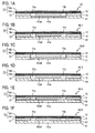
- Fig. 2 is a cross-sectional view illustrating the construction of a first embodiment wherein a front electret type condenser microphone 1 is constructed by the use of an improved condenser section 40 according to the present invention
- Fig. 3 is a bottom plan view of the microphone 1 looking in the direction A in Fig. 2.
- the microphone 1 of this first embodiment includes a capsule 10, a back electrode board 11, an FEP film 12 which is an electret film, a spacer 13, a diaphragm 14, a diaphragm ring 15, a base 16, an FET 17, a chip capacitor 18a, an output terminal 19a, a GND wiring 19b, and an FEP film 20.
- the capsule 10 is a structure in the form of a cylindrical bottom-walled cup made of metal such as aluminum.
- the bottom (closure wall) or called as a front board 10a of the cylindrical bottom-walled cup-like structure is in the form of a circular disc being provided in the center thereof with a receiving sound aperture 10aa in the form of a circular through aperture.
- the diameter of the receiving sound aperture 10aa be preferably on the order of ⁇ 0.4 mm to ⁇ 0.8 mm.
- the front board 10a is formed in its inner surface with a slit 10ad which is a groove or a channel-like cavity extending across and intersecting with the receiving sound aperture 10aa.
- the middle portion of the slit 10ad is in direct communication with a portion of the opening of the receiving sound aperture 10aa. While the slit 10ad may be triangular, square, polygonal, circular, elliptical or of any other shape as viewed in a cross-section perpendicular to the length thereof, the slit 10ad may be utilized as an acoustic resistance slit in the case where it is formed in a V-shape having a triangular cross-section as viewed perpendicularly to the length thereof.
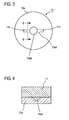
- Fig. 4 is a cross-sectional view taken along the line B-B in Fig. 3 illustrating an instance where the slit 10ad is adapted to serve as an acoustic resistance slit.
- the front board 10a is formed in its inner surface with a V-shaped groove or channel, and the space enclosed with this V-shaped groove or channel and a back electrode board 11 disposed on the inner surface of the front board 10a (the space triangular in a cross-section) serves as a slit 10ad.
- this slit 10ad is used as an acoustic resistance slit, it is desirable that the depth (or slit gap) of the slit 10ad be on the order of 5 ⁇ m to 50 ⁇ m.
- the slit 10ad when the slit 10ad is not used as an acoustic resistance slit, it may be desirably 50 ⁇ m or greater in depth.
- the longitudinal dimension of the slit 10ad may be desirably on the order of 2.7 mm to 3.6 mm, but it is not limited to a specific range, provided that the slit is long enough to communicate the receiving sound aperture 10aa with air vent apertures 11a, 11b which will be described later, and it is desirable that the minor dimension (which may be called width) of the slit be a dimension which corresponds to the diameter of the air vent apertures with which the slit is connected, and may be in the range of 0.4 mm to 0.8 mm by way of example.
- the front board 10a of the capsule 10 is adapted to function as a cover board affixed in intimate contact to the outer surface of the back electrode board 11 of the condenser section 40 improved according to the present invention.
- this construction is nothing else than 'double-decking' the front board 101a acting as a back electrode board in the prior art front electret type condenser microphone shown in Fig. 8 or that it is nothing else than interposing an auxiliary electric conductor layer between the front board 101a and the FEP electret film 102 in the prior art example shown in Fig. 8.
- this 'double wall' structure is charged with great ingenuities which even those skilled in the art could not easily anticipate, as explained hereinabove in relation to the principle of the present invention.
- the back electrode board 11 is disposed on the inner surface of the front board 10a so as to be electrically and mechanically connected with the front board 10a in intimate contact state.
- the back electrode board 11 is a conductive plate-like structure (such as a circular disc, for example) made of brass, stainless steel or the like, and the FEP film 12 is disposed on the surface of the back electrode board 11 on the side opposite from the front board 10a.
- the FEP film 12 should be subjected to polarization treatment to become an electret film after the film disposition, and is preferably on the order of 5 ⁇ m to 30 ⁇ m, more preferably about 25 ⁇ m in thickness. It should be noted that while the electret film is described here as being an FEP, any other polymeric material may be used as the electret film provided that it possesses the electret property.
- the back electrode board 11 is provided with two air vent apertures (through apertures) 11a, 11b at certain distances radially outward from the center thereof and at such positions as not to align with the receiving sound aperture 10aa.
- the air vent apertures 11a, 11b are configured and arranged such that one ends of the air vent apertures 11a, 11b will coincide with the opposite ends of the slit 10ad formed in the front board 10a.
- the opening of the receiving sound aperture 10aa of the front board 10a at the back electrode board 11 side thereof is covered by a receiving sound aperture covering portion 11ab of the back electrode board, while the openings of the air vent apertures 11a, 11b of the back electrode board at the front board 10a side thereof are covered by air vent covering portions 10ab, 10ac, respectively of the front board 10a, so that at least portions of the openings of the air vent apertures 11a, 11b at the front board 10a side and at least a portion of the opening of the receiving sound aperture 10aa at the back electrode board 11 side are connected with each other by the slit 10ad comprising a cavity in a direction perpendicular to the axes of these apertures, which direction is longitudinal of the slit and parallel to the intimately contacted surfaces of the two boards.
- the diameter of the air vent apertures 11a, 11b be preferably on the order of ⁇ 0.4 mm to ⁇ 0.8 mm, and that the distance from the center of the back electrode board 11 to the air vent apertures 11a, 11b be preferably on the order of 0.3 mm to 0.8 mm where the diameter of the entire microphone 1 is ⁇ 4 mm to ⁇ 10 mm.
- the thickness of the back electrode board 11 be preferably on the order of 0.2 mm to 0.8 mm.
- the distance r from the opposite ends of the slit 10ad to the outer peripheral edge of the receiving sound aperture 10aa is preferably equal to or greater than the diameter of the air vent apertures 11a, 11b, and more preferably on the order of 0.9 mm to 1.3 mm.
- the number of the air vent apertures 11a, 11b is not limited to two, but may be more or less than two. Further, their shape is not limited to a circular shape, but it is desirable that the air vent apertures 11a and 11b be formed at positions symmetrical about the center of the receiving sound aperture 10aa for the sake of the frequency characteristic.
- the spacer 13 is disposed on the surface of the FEP electret film 12 on the side opposite from the back electrode board 11.
- the spacer 13 is a plate-like insulator made of polymeric material such as PET, and practically it is preferably in the form of a circular, annular disc (generally doughnut-shaped) having a central opening. As illustrated in Fig. 2, the spacer 13 is arranged such that its outer peripheral edge coincides with the outer peripheral edges of the back electrode board 11 and the FEP film 12 with the planar surface of the spacer in contact with the FEP film 12.
- the spacer 13 is configured and arranged such that the air vent apertures 11a, 11b of the back electrode board are positioned within the central opening of the spacer, so that the air vent apertures 11a, 11b are not closed by the spacer 13. It is desirable that the thickness of the spacer 13 be on the order of 16 ⁇ m to 50 ⁇ m and that the width (difference between the radii of the outer and inner peripheries) of the annular portion of the spacer 13 be on the order of 0.4 mm to 0.8 mm.
- the diaphragm 14 is disposed on the surface of the spacer 13 on the side opposite from the back electrode board 11.
- the diaphragm 14 is an electrically conductive membrane comprising a polymeric molecular film 14a such as PET and a metallic film such as nickel (Ni), aluminum (Al), titanium (Ti) or the like vapor deposited on one side surface of the polymeric molecular film to form a conductive layer 14b. It is desirable that the thickness of the polymeric molecular film be on the order of 2 ⁇ m to 4 ⁇ m and that the thickness of the metallic film be on the order of 200 ⁇ to 300 ⁇ .
- the diaphragm 14 is configured and arranged such that its outer peripheral edge coincides with the outer peripheral edge of the spacer 13 and is disposed on the spacer 13 with the conductive layer side (metallic film 14b) facing the diaphragm ring 15.
- the diaphragm 14 is thus sandwiched and firmly secured between the diaphragm ring 15 and the spacer 13 with a predetermined gap spaced by the thickness of the spacer 13 from the FEP film 12. Desirably, this gap is on the order of 16 ⁇ m to 50 ⁇ m.
- the diaphragm ring 15 is a cylindrical member which may be made of brass, stainless steel or the like.
- the diaphragm ring 15 is configured and arranged such that its outer peripheral edge coincides with the outer peripheral edge of the spacer 13 to thereby secure the diaphragm 14 as mentioned above and to electrically connect the ring 15 with the conductive layer 14b of the diaphragm 14.
- the conductive layer 14b of the diaphragm 14 is bonded to the diaphragm ring 15 by a conductive adhesive, for example.
- the height of the diaphragm ring 15 depends on the height of the entire microphone 1, it is desirable that the height of the diaphragm ring 15 be on the order of 0.6 mm to 2.0 mm for the microphone 1 having a height of about 1 to 3 mm. It is to be noted that the diaphragm ring 15 may be two separable rings and disposed on the diaphragm 14 side and on the base 16 side, respectively.
- the height of the ring on the diaphragm 14 side is desirably on the order of 0.3 mm to 0.5 mm while the height of the ring on the base 16 side is desirably on the order of 0.3 mm to 1.5 mm (assuming that the height of the entire microphone 1 is on the order of 1 to 3 mm). Further, it is desirable that the lateral thickness (difference between the radii of the outer and inner peripheries) of the diaphragm ring 15 be on the order of 0.4 mm to 0.8 mm.
- the base 16 is disposed on the end of the diaphragm ring 15 opposite from the diaphragm 14.
- the base 16 is a disc-like plate formed of an insulator such as glass epoxy (FR-4, for example) or the like and is provided in its inner surface with an electric wiring (not shown) which is electrically connected with the diaphragm ring 15.
- an electric wiring not shown
- mounted on the inner surface of the base 16 are the impedance converting FET 17 and the chip capacitor 18a which are electrically interconnected by electric wiring (not shown) to constitute an electric circuit.
- the base 16 is further provided with through holes 16b, 16c the interior surfaces of which are formed with metallic film.
- the output of the electric circuit formed in the inner surface of the base 16 is electrically connected via the through hole 16b with the output terminal 19a formed on the outer surface of the base 16 while the GND of the electric circuit formed in the inner surface of the base 16 is electrically connected via the through hole 16c with the GND wiring 19b provided on the outer surface of the base 16.
- the GND wiring 19b is in turn electrically connected with one end 10c, for example, of the capsule 10. It is desirable that the thickness of the base 16 be on the order of 0.2 mm to 0.8 mm.
- the base 16 has a directivity modulating sound aperture 16a formed therethrough. It is desirable that the directivity modulating sound aperture 16a be ⁇ 0.3 mm to ⁇ 1 mm in diameter and that it be located at a distance of about 1 mm to 2 mm from the center of the base 16 (for the entire microphone 1 having a diameter of about ⁇ 4 mm to ⁇ 10 mm).
- the number of the directivity modulating sound aperture 16a is not limited to one, but may be more than one. Further, its shape is not limited to a circular shape, either.
- the inner surface of the cylindrical side wall 10b of the capsule 10 is formed with an insulator film such as FEP film 20.
- the FEP film 20 acts to prevent the diaphragm ring 15 and the capsule 10 from contacting each other to electrically short-circuit the diaphragm ring 15 with the capsule 10. It is desirable that the FEP film 20 be on the order of 5 ⁇ m to 20 ⁇ m in thickness. In place of the FEP film 20, any other suitable insulating materials such as PET may be used.
- the open rear end (the end opposite from the front board 10a) of the capsule 10 is folded inwardly as a folded end portion 10c to firmly hold a portion of the base 16, whereby the back electrode board 11, FEP film 12, spacer 13, diaphragm 14, diaphragm ring 15 and base 106 are entirely sandwiched and held in place between the folded end portion 10c and the inner surface of the front board 10.
- the capsule 10 is a single capsule 10:
- a planar plate of aluminum or the like is formed with a slit 10ad and a receiving sound aperture 10aa as by a pressing process. Then, insulator FEP film 20 is heat welded in the form of a strip to a portion of the thus pressed planar aluminum plate, followed by drawing the resulting planar aluminum plate to form a capsule 10 in the shape of a cylindrical bottom-walled cup having a front board 10a which is a closure wall.
- the back electrode board 11 is a back electrode board 11
- FEP film 12 is heat welded to a planar plate of brass or the like. After being subjected to polarization treatment, the resulting planar plate is formed with air vent apertures 11a, 11b as by pressing process and/or machining process to form a back electrode board 11.
- the diaphragm 14 is aphragm 14:
- a diaphragm 14 is formed by depositing metal such as Ti or the like entirely on one side surface of a polymeric molecular sheet 14a such as PET or the like as by a sputtering process.
- the assembly :
- the back electrode board 11, spacer 13, diaphragm 14, diaphragm ring 15 and base 16 are stacked successively in the order named on the inner surface of the front board 10a and are securely held in place in the capsule 10 by folding the rear end of the capsule 10 as described above.
- the back electrode board 11 provided with air vent apertures 11a, 11b is placed on the inner surface of the front board 10a while the polarized FEP electret film 12 is disposed on the surface of the back electrode board 11 opposite from the front board 10a, and the diaphragm 14 is disposed in opposition to the back electrode board 11 on the surface of the FEP electret film 12 opposite from the back electrode board 11 with the spacer 13 interposed therebetween which extends around the outer periphery of the opposite surface of the FEP electret film 12 to thereby constitute a condenser section.
- the slit may be formed in either one of the intimately contacted surfaces of the front board 10a and the back electrode board 11, the slit 10 ad is formed in the surface of the front board 10a on the back electrode board 11 side in this first embodiment, and the openings of the air vent apertures 11a, 11b on the front board 10a side is covered by the air vent covering portions 10ab, 10ac, respectively of the front board 10a while the opening of the receiving sound aperture 10aa on the back electrode board 11 side is covered by the back electrode board side 11 so that at least portions of the openings of the air vent apertures 11a, 11b on the front board 10a side and at least a portion of the opening of the receiving sound aperture 10aa on the back electrode board 11 side are communicated with each other by the slit 10ad.
- the length of ingress path of grit from the outside to the FEP electret film 12 may be extended to the length equal to the depth of the receiving sound aperture 10aa formed through the front board 10a plus the depth of the air vent apertures 11a, 11b of the back electrode board 11 further plus the length of the slit 10ad.
- the addition of the slit 10ad provides for making the ingress passage for grit from the receiving sound aperture 10aa to the FEP 12 relatively thin as compared with the diameter of the aperture to thereby enhance the effect of preventing the ingress of grit.
- any grit which has found its way into the capsule through the directivity modulating sound aperture 16a is prevented from reaching the FER electret film 12 by the diaphragm 14, whereby sensitivity degradation of the microphone 1 due to ingress of grit through this route may also be prevented.
- the slit 10ad is formed as a V-shaped groove or channel so as to be triangular in a cross-section perpendicular to the length thereof, it may function as an acoustic resistance slit.
- the characteristic of the microphone 1 may be rendered unidirectional if the construction is such that the directivity modulating sound aperture 16a is eliminated.
- the characteristic of the microphone 1 may be nondirectional by forming the slit 10ad so as not to act as an acoustic resistance slit and eliminating the directivity modulating sound aperture 16a.
- the characteristic of the microphone 1 may be bidirectional by forming the slit 10ad so as not to act as an acoustic resistance slit and providing the directivity modulating sound aperture 16a.
- the resultant microphone may have a high acoustic performance comparable to that of the microphone of the conventional back electret type.
- the present invention does not require the ring 202 as required in the conventional back electret type microphone 200 shown in Fig. 8, so that it allows for slimming the microphone (lowering the profile of the microphone) by the thickness of the ring 202. It is thus to be appreciated that the present invention provides for downsizing and slimming while retaining the performance of the microphone of the conventional back electret type.
- the ring 202 has required a thickness of 0.2 mm at the minimum and greater than that.
- the reason is that if the ring 202 is made thinner than that, the ring 202 would become distorted under the stress from the base 209 side during the crimping of the microphone 200 (folding of the open end of the capsule inwardly and downwardly) and hence the diaphragm 204 bonded to the ring 202 would also be distorted, resulting in deleteriously affecting the acoustic performance. Therefore, this embodiment eliminating the need for providing the ring 202 allows for lowering the profile of the microphone by greater than 0.2 mm as compared with the prior art.
- the present invention makes it possible to enhance the performance of the microphone while maintaining the size of the conventional back electret type microphone.
- the number of component parts required may be reduced by omitting the ring 202, and hence the cost of manufacture as well as the cost of parts may be reduced.
- the diaphragm 14 is adhesively bonded to the diaphragm ring 15 having an adequate thickness, the distortion which the diaphragm 14 may suffer during the crimping step may be greatly reduced as compared with the prior art in which the diaphragm 204 was bonded to the thin ring 202.
- the slit 10ad is formed in the inside surface of the front board 10a as shown in Fig. 2
- a slit 11ad may be formed in the surface of the back electrode board 11 on the front board 10a side as in the microphone 50 illustrated as a second embodiment in Fig. 5, rather than forming a slit in the front board 10a.
- the opening of the receiving sound aperture 10aa on the back electrode board side is covered by air vent covering portion 11ab of the back electrode board 11 while the openings of the air vent apertures 11a and 11b on the front board side are covered by air vent covering portions 10ab and 10ac of the front board 10a.
- the slit 11ad may be a groove or channel formed in the surface of the back electrode board 11 on the front board 10a side so as to connect the openings of said two air vent apertures 11a and 11b across the receiving sound aperture 10aa such that the middle portion of the slit 11ad communicates directly with a portion of the opening of the receiving sound aperture 10aa.
- the slit 11ad may be triangular, square, polygonal, circular, elliptical or of any other shape as viewed in a cross-section perpendicular to the length thereof, the slit 11ad may be utilized as an acoustic resistance slit if it is formed as a V-shaped groove or channel so as to be triangular in a cross-section as viewed perpendicularly to the length thereof.
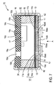
- Fig. 6 illustrates a microphone 60 according to a third embodiment in which an air vent aperture 11c is formed through the back electrode board 11 while two receiving sound apertures 10ba, 10bb are formed through the front board 10a at predetermined distances radially outwardly from the center thereof (at positions where the through apertures of the two boards do not align with each other).
- the opening of the air vent aperture 11c on the front board side is covered by an air vent covering portion 10bc of the front board 10a while the openings of the two receiving sound apertures 10ba, 10bb on the back electrode board side are covered by air vent covering portions of the back electrode board 11.
- a slit 10ad is formed in the inner surface of the front board 10a so as to connect the openings of the two receiving sound apertures 10ba, 10bb at the back electrode board side and such that the central portion of the slit 10ad is communicated directly with the opening of the air vent aperture 11c on the front board 10a side.
- the air vent aperture 11c and the receiving sound apertures 10ba, 10bb are communicated with each other through the slit 10ad.
- the receiving sound apertures 10ba and 10bb are positioned symmetrically about the longitudinal midpoint of the front board 10a.
- the slit 10ad may be formed in the back electrode board 11 in a manner same as in the embodiment illustrated in Fig. 5, rather than in the front board 10a. (not shown)
- Fig. 7 illustrates a microphone 70 according to a fourth embodiment in which no slit is formed in either the inside surface of the front board 10a or the surface of the back electrode board 11 on the front board 10a side, and instead the back electrode board is placed over and secured to the inside surface of the front board 10a with an annular disc-like, electrically conductive back electrode board spacer 42 interposed therebetween so that a gap 42ad having a gap depth determined by the back electrode board spacer 42 is defined between the back electrode board and the front board 10a acting as the cover board.
- the front board 10a is formed generally in its center with a through aperture comprising a receiving sound aperture 10aa while the back electrode board 11 is provided with two air vent apertures 11a, 11b at predetermined distances radially outward from the center thereof (that is, at positions where the apertures 11a, 11b are not axially aligned with the receiving sound aperture 10aa).
- the openings of the air vent apertures 11a, 11b of the back electrode board 11 at the front board 10a side are covered by air vent covering portions 10ab, 10ac, respectively of the front board 10a while the opening of the receiving sound aperture 10aa of the front board 10a at the back electrode board 11 side is covered by a receiving sound aperture covering portion 11ab of the back electrode board 11, and the gap 42ad defined between the back electrode board and the front board (the cover board) and having a gap depth determined by the back electrode board spacer 42 is adapted to act as the aforesaid connecting slit, so that the receiving sound aperture 10aa of the front board 10a and the two air vent apertures 11a, 11b of the back electrode board 11 are connected with each other by this connecting slit 42ad.
- this embodiment is also capable of a modified form in which the back electrode board is provided with a single air vent aperture rather than two air vent apertures 11a, 11b while the front board 10a is provided with two receiving sound apertures instead of the single receiving sound aperture 10aa and a further modified form in which the electret film is disposed on the surface of the diaphragm 14 on the back electrode board 11 side rather than on the surface of the back electrode board 11 on the diaphragm 14 side. (not shown)
- the role of the connecting slit in this embodiment is filled by the gap between the back electrode board and the cover board. It will be appreciated that this embodiment is very useful in the case that the two boards are extremely thin so that if a slit is formed in the surface of either one of the boards, the strength of the board would be exceedingly weakened.
- This connecting slit or gap as shown in Fig.7 is also defined so as to extend perpendicularly to the axes of the through apertures formed in both the cover board and the back electrode board, and is, therefore, apparently equivalent to the connecting slit in the other embodiments which is formed in either one or both of the surfaces of the back electrode board and the cover board which are secured together in intimate contact.
- a front board (cover board) having a receiving sound aperture formed therethrough is placed over and affixed to a back electrode board having air vent apertures formed therethrough at positions not aligning with the receiving sound aperture of the front board, and the receiving sound aperture and the air vent apertures are communicated with each other in a direction perpendicular to the axes of the apertures by a slit defined between the front board and the back electrode board.
Abstract
Description
- This invention relates to a condenser type microphone, and more particularly to a condenser microphone utilizing an electret (permanently electrification) phenomenon.
- Heretofore, the electret condenser microphone utilizing variations in capacitance of a condenser comprising an electrically conductive vibration diaphragm and an electrically conductive board having formed thereon an electret film (permanently electrified film) such as FEP (Fluoro Ethylene Propylene) to transform a sound pressure into an electrical signal has been known (see Japanese Utility Model Registration No. 2548543 and Japanese Patent Application Publication No. 11-150795). The electret condenser microphone falls roughly into two categories: the front electret type and the back electret type, based on the positional relationship between the diaphragm and the electret film. Generally, the front electret type is superior in terms of miniaturization whereas the back electret type is superior in terms of performance and cost. The general construction of these two types of electret condenser microphone will be described below.
- Fig. 8 is a cross-sectional view illustrating the structure of a
microphone 100 which is an example of the electret condenser microphone of the prior art front electret type. - As illustrated in Fig. 8, the
microphone 100 includes acapsule 101 in the form of a cylindrical bottom-walled cup made of metal such as aluminum and having an integrally formed bottom wall that is called hereinafter as afront board 101a; anFEP 102 which is an electret film; an annular disc-like spacer 103 formed of an electric insulator such as PET (polyester) or the like; adiaphragm 104 comprising afilm 104a such as PET and a metal layer such as nickel vapor-deposited on thefilm 104a;cylindrical rings base 107 formed of glass epoxy or the like and having a directivity modulatingsound aperture 107a formed therethrough and an impedance converting FET (field-effect transistor) 108 and achip capacitor 109 mounted thereon. - The
front board 101a is formed with a receiving sound aperture 101aa which is a through aperture, and anFEP film 102 which is an insulator and has been subjected to polarization treatment to become the electret film is deposited on the entire inner wall surface of thecapsule 101 except for its upper foldedend portion 101c. TheFEP 102,spacer 103,diaphragm 104,ring 105,ring 106 andbase 107 are stacked successively in the order named on theFEP film 102 on the inner wall side of thefront board 101 a. The upper end (or the rear end if the front board is considered as the front end as it faces a sound source) of thecapsule 101 is folded inwardly to force an end face of thebase 107 towards thefront board 101a, which in turn forces thespacer 103,diaphragm 104,ring 105 andring 106 as a unit towards thefront board 101a to be held in place. - In addition, the FET 108 and the
chip capacitor 109 are mounted to the inner wall of thebase 107, and the output of an electric circuit constituted by these components is electrically connected via throughholes output terminal 110a and GND (ground)wiring 110b provided on the outer wall of thebase 107. TheGND wiring 110b is in turn electrically connected with thecapsule 101 at the foldedportion 101c. The FET 108 and thechip capacitor 109 are electrically connected with thering 106 through a wiring (not shown) on thebase 107. Thering 106 is electrically connected with thering 105 which is in turn electrically connected with the vapor-depositedmetallic film 104b on thediaphragm 104. - Fig. 9 is a cross-sectional view illustrating the structure of a
microphone 200 which is an example of the electret condenser microphone of the prior art back electret type. - As shown in Fig. 9, the
microphone 200 includes acapsule 201 in the form of a cylindrical bottom-walled cup made of metal such as aluminum and having an integrally formedfront board 201 a;cylindrical rings like spacer 203 formed of PET (polyester) or the like; adiaphragm 204 comprising afilm 204a such as PET and ametal layer 204b such as nickel vapor-deposited on thefilm 204a; anFEP 205 which is an electret film subjected to polarization treatment; a plate-likeback electrode board 206 formed of stainless steel or the like; acylindrical insulator holder 207; and abase 209 formed of glass epoxy or the like and having a directivity modulatingsound aperture 209a formed therethrough, and an impedance converting FET 210 and achip capacitor 211 mounted thereon. Thefront board 201 a is formed with receivingsound apertures 20 1 ba, 20 1 bb and 201bc which are through apertures, and theback electrode board 206 has the FEP 205 disposed on the front side surface thereof and is formed withair vents - The
ring 202,diaphragm 204, andspacer 203 are stacked successively in the order named on the inner side surface of thefront board 201a, and theholder 207 and a portion of theback electrode board 206 on theFEP 205 side are disposed on thespacer 203. Thering 208 is further placed on theback electrode board 206, and thebase 209 is placed on theholder 207 andring 208. The thus disposedrings spacer 203,diaphragm 204,back electrode board 206,holder 207 andbase 209 are adapted to be forced as a unit towards thefront board 201a to be held in place by folding therear end portion 201c of thecapsule 201 inwardly to force an end face of thebase 209 towards thefront board 201a. - In addition, the FET 210 and the
chip capacitor 211 are mounted to the inner wall of thebase 209, and the output of an electric circuit constituted by these components is electrically connected via throughholes GND wiring 212b provided on the outer surface of thebase 209. TheGND wiring 212b is in turn electrically connected with thecapsule 201. The FET 201 and thechip capacitor 211 are electrically connected with thering 208 through a wiring (not shown) on thebase 209. Thering 208 and thering 202 are electrically connected with theback electrode board 206 and thefront board 201a, respectively. - However, the constructions of these prior art electret condenser microphones of Figs. 8 and 9 have the drawback that it is liable to deteriorate in sensitivity due to ingress of grit and dust (which will be referred to simply as grit hereinafter) from the outside to the electret film.
- For example, in the case of the electret condenser microphone of the front electret type as shown in Fig. 8, the
FEP 102 which is an electret film is formed directly on the inner surface of thefront board 101a. Consequently, the length of ingress path of grit from the outside of thecapsule 101 to theFEP electret film 102 is essentially equal to only the depth of the receiving sound aperture 101aa, that is, the thickness of thefront board 101a, so that the likelihood of grit in the outside air to reach theFEP 102 is very high. It is empirically known that if the grit reaches and attaches to theFEP electret film 102, the potential of the capacitor comprising thediaphragm 104 and thefront board 101a is reduced, leading to deterioration in sensitivity of themicrophone 100. - In the case of the electret condenser microphone of the back electret type as well, if the
base 209 is provided with the directivity modulatingsound aperture 209a to provide bidirectional properties as shown in Fig. 9, grit is likely to find its way through the directivity modulatingsound aperture 209a into the capsule. And if the grit which has thus found its way into the capsule further passes through theair vents FEP electret film 102, it may result in deterioration in sensitivity of the microphone, as is the case with the front electret type as discussed above. - It is the microphone disclosed in the above mentioned Japanese Utility Model Registration No. 2548543 that was devised to overcome this drawback. The essential part of this device is shown in Figs. 10 and 11.
- Figs. 10 and 11 illustrate the improved construction of the receiving sound aperture 101aa in the
front board 101a of theprior art microphone 100 shown in Fig. 8. Fig. 10 is a cross-sectional view looking in the direction of arrows C from the sectioned plane indicated in Fig. 11. - This improved through aperture comprises a circular, first recess 101-1 cut in the
front board 101a from its front face toward the rear side (from the lower side to the upper side of the front board as viewed in Fig. 10) as indicated by the arrow A to a depth Q equal to approximately half the thickness P of the front board, with several (three, for instance) circumferentially spaced joint portions 101-2 (see Fig. 11) left around the inner periphery of the recess. Then, an annular, second recess 101-3 is cut in thefront board 101a from its rear face toward the front side to a depth (P - Q + R) somewhat greater than the remaining half (P-Q) of the front board thickness. - It is to be noted that the first and second recesses 101-3 are sized such that the inner diameter of the second annular recess will touch the outer diameter of the first circular recess 101-1 so that the two recesses will communicate with each other through a slit 101-4 having a depth (R). It is to be understood that when the annular recess 101-3 is formed, the area 101-5 left inward of the annular recess is prevented from being separated from the front board by the joint portions 101-2.
- With this improved receiving sound aperture (through aperture) formed as discussed above, grit in the outside air may pass through the first recess 101-1 from the front side and find its way via the slit 101-4 having a depth (R) and then through the second recess 101-3 before reaching the FEP
film 102. The ingress of grit may be suppressed by setting the depth R of the slit 101-4 to be small. - However, such improved through aperture must be formed by cutting two recesses into the front board from its opposite sides with a highly precise alignment so as to define a slit 101-4 generally in the middle of the thickness of the front board. This undesirably requires the increased cost of manufacture as well as time and trouble in manufacture. In addition, it is solely the slit 101-4 that contributes to suppressing the ingress of grit, and the length of ingress path of grit remains unchanged, that is, it is essentially equal to the thickness of the front board, so that this improved through aperture has been found insufficient with a limited effect of suppressing the ingress of grit.
- This invention addresses the aforesaid prior art problems and contemplates to provide a microphone which is capable of suppressing sensitivity degradation due to ingress of grit from the outside to the electret film.
- In order to solve the aforesaid problems, according to this invention, an improvement is provided in the condenser section which is comprised of an electrically conductive vibration diaphragm serving as one electrode; an electrically conductive back electrode board serving as an opposite electrode located in parallel opposition to and spaced from the diaphragm with a predetermined depth of gap with an electrically insulating spacer therebetween; and an electret layer formed on either one of the surface of the back electrode board on the diaphragm side and the surface of the diaphragm on the back electrode board side, and further a cover board affixed to the back electrode board so that it covers the front surface of the back electrode board opposite from the diaphragm side surface to define an improved condenser section. The improved condenser section is accommodated in a capsule to comprise an improved electret condenser microphone.
- In the improved condenser section, the cover board is affixed to the back electrode board either it is affixed in intimate contact directly to the back electrode board or it is secured to the back electrode board with an annular disc-like back electrode board spacer interposed therebetween. In addition, the back electrode board and the cover board have respective air vent apertures formed therethrough which are positioned so as not to be in alignment with each other, and in the case of intimate contact to each other, at least one of the intimately affixed surfaces has a connecting slit formed therein which extends perpendicularly to the axis of the air vent apertures and connects the air vent apertures of the back electrode board and of the cover board positioned so as not to be in alignment with each other whereby the electret film is communicated with the outside air through the connecting slit and the air vent apertures of the two boards thus connected by the slit. Alternatively, in the case where the cover board is secured to the back electrode board with an annular disc-like back electrode board spacer interposed therebetween, a gap or space formed between the back electrode board and the cover board and having a predetermined gap depth defined by the back electrode board spacer is adapted to act as the connecting slit whereby the electret film is communicated with the outside air through the connecting slit and the air vent apertures of the two boards connected by the slit. With this construction, it will be appreciated that the length of ingress path of grit from the outside to the electret film may be extended to the length equal to the depth of the air vent aperture(s) acting as the receiving sound aperture(s) formed through the front board plus the depth of the air vent aperture(s) formed through the back electrode board (that is, the thickness of the front board plus the thickness of the back electrode board) and further plus the length of the connecting slit, and that the effect of suppressing the ingress of grit may be enhanced by the provision of the connecting slit. As a result, it is possible to reduce the probability that the grit which may find its way from the outside into the capsule may reach the electret film.
- In addition, it should be noted that the grit which has found its way from the outside air into the capsule through the directivity modulating sound aperture is prevented from reaching the electret film by the diaphragm since it is provided on the electret film formed on the back electrode board with a ring-shaped spacer interposed therebetween which is placed on the periphery of the surface of the back electrode board opposite from the front board.
-
- Figs. 1A-1F are cross-sectional views illustrating six alternative forms of construction of the improved condenser section according to the present invention;
- Fig. 2 is a cross-sectional view illustrating the construction of the microphone according to a first embodiment of the present invention;
- Fig. 3 is a bottom plan view of the microphone looking in the direction A in Fig. 2;
- Fig. 4 is a cross-sectional view taken along the line B-B in Fig. 3 illustrating an instance where the slit is adapted to serve as an acoustic resistance slit;
- Fig. 5 is a cross-sectional view illustrating the construction of the microphone according to a second embodiment of the present invention;
- Fig. 6 is a cross-sectional view illustrating the construction of the microphone according to a third embodiment of the present invention;
- Fig. 7 is a cross-sectional view illustrating the construction of the microphone according to a fourth embodiment of the present invention;
- Fig. 8 is a cross-sectional view illustrating the construction of the conventional front electret type condenser microphone;
- Fig. 9 is a cross-sectional view illustrating the construction of the conventional back electret type condenser microphone;
- Fig. 10 is a cross-sectional view illustrating the front board section of the still prior art example which improved the prior art as shown in Fig. 8; and
- Fig. 11 is a plan view of the central portion of the front board looking in the direction A in Fig. 10.
-
- Figs. 1A-1F are cross-sectional views illustrating six alternative forms of construction of the improved condenser section according to the present invention. The principle of the present invention will first be explained with reference to these illustrations.
- As is discussed above in The Prior Art section with reference to Fig. 8, the front electret type condenser microphone includes a condenser section comprising a
conductive diaphragm 104 constituting one electrode; afront board 101a of acapsule 101 serving as an opposite electrode located in parallel opposition to and at a predetermined spacing from the diaphragm; and an electret film formed on either one (front board 101a, for example) of the opposed surfaces of theseboards conductive capsule 101. - The microphone according to the present invention is provided by improving the prior art condenser section described just above to define an
improved condenser section 40 as shown in Fig. 1A and accommodating theimproved condenser section 40 in a conductive capsule. - While the
capsule 10 is described as being in the form of a cylindrical cup, it is because the front board of the capsule is considered to form one component part of the condenser section. It should be appreciated that the configuration of the capsule is not limited to the cylindrical cup, but in principle may be a cylindrical form with its opposite ends open. - The
improved condenser section 40 comprises an electricallyconductive vibration diaphragm 14 serving as one electrode, aback electrode board 11 located in parallel opposition to and at a predetermined spacing from the diaphragm, and anelectret film 12 formed on either one (theback electrode board 11, for instance) of the opposing surfaces of the back electrode board and the diaphragm, and acover board 41 affixed in intimate contact to the outer surface of the back electrode board which must necessarily be provided with throughapertures - The
cover board 41 is also provided with a throughaperture 41 a, but at a location where it does not align with the throughapertures cover board 41 intimately contacting the surface of the back electrode board to establish communication between the throughaperture 41 a in thecover board 41 and throughapertures back electrode board 11. - The depth of the slit as measured from the aforesaid surface of the cover board, the longitudinal length of the slit and the cross-sectional shape of the slit as viewed in a direction perpendicular to the length thereof are determined so as to enhance the effect of preventing the ingress of grit.
- In a microphone constructed by using the improved
condenser section 40 obtained as described above, it will be appreciated that the length of ingress path of grit from the outside to the electret film may be extended to the length equal to the depth of the air vent apertures formed in the back electrode board and the cover board plus the length of the connecting slit. This, together with the effect of suppressing the grit ingress by the connecting slit itself, makes it possible to reduce the probability that the grit which may find its way from the outside into the capsule may reach the electret film. - While the
improved condenser section 40 having the slit formed in the surface of the cover board intimately contacting the surface of the back electrode board is illustrated in Fig. 1A, the slit may be formed in the surface of the back electrode board intimately contacting the surface of the cover board to provide an improved condenser section 40-1 as shown in Fig. 1B, or alternatively may be formed in both of the intimately contacted surfaces of the two boards, although not shown. - While the electret film is described as being formed on the surface of the back electrode board on the diaphragm side in the foregoing examples, it may be formed on the surface of the diaphragm on the back electrode board side as shown in Fig. 1C. In this instance as well, an improved condenser section 40-2 may be obtained in which the slit is formed in the surface of the cover board intimately contacting the surface of the back electrode board. Or alternatively, an improved condenser section 40-3 may be obtained in which the slit is formed in the surface of the back electrode board intimately contacting the surface of the cover board, as shown in Fig. 1D. In a yet alternative, the slit may be formed in both of the intimately contacted surfaces, although not shown.
- In a still another alternative form, an improved condenser section 40-4 as shown in Fig. 1E may be obtained in which the cover board is affixed to the back electrode board with an annular disc-like, conductive (metal) back
electrode board spacer 42 interposed therebetween, and a gap 42ad formed between the back electrode board and the cover board and having a predetermined gap depth defined by the backelectrode board spacer 42 is adapted to act as the connecting slit. While the electret film is described as being formed on the surface of the back electrode board on the diaphragm side in this instance of Fig. 1E, an improved condenser section 40-5 may be obtained in which the electret film is formed on the surface of the diaphragm on the back electrode board side, as shown in Fig. 1F. - Desirably, the back
electrode board spacer 42 is a conductive annular disc having a very thin thickness just enough to define the aforesaid gap depth. Or alternatively, the back electrode board spacer may be formed on the back electrode board by metal plating or any other appropriate attaching technique if it is desired to make the gap depth defined by the spacer very thin. - Various embodiments of this invention will be described below with reference to the accompanying drawings. It is to be noted that the same or like parts in the various drawings will be referred to by the same reference numbers or symbols and will not be discussed again in detail.
- Fig. 2 is a cross-sectional view illustrating the construction of a first embodiment wherein a front electret type condenser microphone 1 is constructed by the use of an
improved condenser section 40 according to the present invention, and Fig. 3 is a bottom plan view of the microphone 1 looking in the direction A in Fig. 2. - As shown in Fig. 2, the microphone 1 of this first embodiment includes a
capsule 10, aback electrode board 11, anFEP film 12 which is an electret film, aspacer 13, adiaphragm 14, adiaphragm ring 15, abase 16, anFET 17, achip capacitor 18a, anoutput terminal 19a, aGND wiring 19b, and anFEP film 20. - The
capsule 10 is a structure in the form of a cylindrical bottom-walled cup made of metal such as aluminum. As illustrated in Fig. 2, the bottom (closure wall) or called as afront board 10a of the cylindrical bottom-walled cup-like structure is in the form of a circular disc being provided in the center thereof with a receiving sound aperture 10aa in the form of a circular through aperture. It is desirable that the diameter of the receiving sound aperture 10aa be preferably on the order of 0.4 mm to 0.8 mm. Thefront board 10a is formed in its inner surface with a slit 10ad which is a groove or a channel-like cavity extending across and intersecting with the receiving sound aperture 10aa. The middle portion of the slit 10ad is in direct communication with a portion of the opening of the receiving sound aperture 10aa. While the slit 10ad may be triangular, square, polygonal, circular, elliptical or of any other shape as viewed in a cross-section perpendicular to the length thereof, the slit 10ad may be utilized as an acoustic resistance slit in the case where it is formed in a V-shape having a triangular cross-section as viewed perpendicularly to the length thereof. - Fig. 4 is a cross-sectional view taken along the line B-B in Fig. 3 illustrating an instance where the slit 10ad is adapted to serve as an acoustic resistance slit.
- In this instance, as illustrated in Fig. 4, the
front board 10a is formed in its inner surface with a V-shaped groove or channel, and the space enclosed with this V-shaped groove or channel and aback electrode board 11 disposed on the inner surface of thefront board 10a (the space triangular in a cross-section) serves as a slit 10ad. In the case where this slit 10ad is used as an acoustic resistance slit, it is desirable that the depth (or slit gap) of the slit 10ad be on the order of 5 µm to 50 µm. In contrast, when the slit 10ad is not used as an acoustic resistance slit, it may be desirably 50 µm or greater in depth. Further, for the microphone 1 having a diameter of about 6 mm, the longitudinal dimension of the slit 10ad may be desirably on the order of 2.7 mm to 3.6 mm, but it is not limited to a specific range, provided that the slit is long enough to communicate the receiving sound aperture 10aa withair vent apertures - In this embodiment, the
front board 10a of thecapsule 10 is adapted to function as a cover board affixed in intimate contact to the outer surface of theback electrode board 11 of thecondenser section 40 improved according to the present invention. - At a glance, it may be merely promptly judged that this construction is nothing else than 'double-decking' the
front board 101a acting as a back electrode board in the prior art front electret type condenser microphone shown in Fig. 8 or that it is nothing else than interposing an auxiliary electric conductor layer between thefront board 101a and theFEP electret film 102 in the prior art example shown in Fig. 8. However, it should be appreciated that this 'double wall' structure is charged with great ingenuities which even those skilled in the art could not easily anticipate, as explained hereinabove in relation to the principle of the present invention. - More specifically, as shown in Fig. 2, the
back electrode board 11 is disposed on the inner surface of thefront board 10a so as to be electrically and mechanically connected with thefront board 10a in intimate contact state. Theback electrode board 11 is a conductive plate-like structure (such as a circular disc, for example) made of brass, stainless steel or the like, and theFEP film 12 is disposed on the surface of theback electrode board 11 on the side opposite from thefront board 10a. TheFEP film 12 should be subjected to polarization treatment to become an electret film after the film disposition, and is preferably on the order of 5 µm to 30 µm, more preferably about 25 µm in thickness. It should be noted that while the electret film is described here as being an FEP, any other polymeric material may be used as the electret film provided that it possesses the electret property. - In addition, the
back electrode board 11 is provided with two air vent apertures (through apertures) 11a, 11b at certain distances radially outward from the center thereof and at such positions as not to align with the receiving sound aperture 10aa. As is noted in Figs. 3 and 4, theair vent apertures air vent apertures front board 10a. With this arrangement, the opening of the receiving sound aperture 10aa of thefront board 10a at theback electrode board 11 side thereof is covered by a receiving sound aperture covering portion 11ab of the back electrode board, while the openings of theair vent apertures front board 10a side thereof are covered by air vent covering portions 10ab, 10ac, respectively of thefront board 10a, so that at least portions of the openings of theair vent apertures front board 10a side and at least a portion of the opening of the receiving sound aperture 10aa at theback electrode board 11 side are connected with each other by the slit 10ad comprising a cavity in a direction perpendicular to the axes of these apertures, which direction is longitudinal of the slit and parallel to the intimately contacted surfaces of the two boards. - It is desirable that the diameter of the
air vent apertures back electrode board 11 to theair vent apertures back electrode board 11 be preferably on the order of 0.2 mm to 0.8 mm. The distance r from the opposite ends of the slit 10ad to the outer peripheral edge of the receiving sound aperture 10aa is preferably equal to or greater than the diameter of theair vent apertures air vent apertures air vent apertures - The
spacer 13 is disposed on the surface of theFEP electret film 12 on the side opposite from theback electrode board 11. Thespacer 13 is a plate-like insulator made of polymeric material such as PET, and practically it is preferably in the form of a circular, annular disc (generally doughnut-shaped) having a central opening. As illustrated in Fig. 2, thespacer 13 is arranged such that its outer peripheral edge coincides with the outer peripheral edges of theback electrode board 11 and theFEP film 12 with the planar surface of the spacer in contact with theFEP film 12. In addition, thespacer 13 is configured and arranged such that theair vent apertures air vent apertures spacer 13. It is desirable that the thickness of thespacer 13 be on the order of 16 µm to 50 µm and that the width (difference between the radii of the outer and inner peripheries) of the annular portion of thespacer 13 be on the order of 0.4 mm to 0.8 mm. - The
diaphragm 14 is disposed on the surface of thespacer 13 on the side opposite from theback electrode board 11. Thediaphragm 14 is an electrically conductive membrane comprising a polymericmolecular film 14a such as PET and a metallic film such as nickel (Ni), aluminum (Al), titanium (Ti) or the like vapor deposited on one side surface of the polymeric molecular film to form aconductive layer 14b. It is desirable that the thickness of the polymeric molecular film be on the order of 2 µm to 4 µm and that the thickness of the metallic film be on the order of 200 Å to 300 Å. - The
diaphragm 14 is configured and arranged such that its outer peripheral edge coincides with the outer peripheral edge of thespacer 13 and is disposed on thespacer 13 with the conductive layer side (metallic film 14b) facing thediaphragm ring 15. Thediaphragm 14 is thus sandwiched and firmly secured between thediaphragm ring 15 and thespacer 13 with a predetermined gap spaced by the thickness of thespacer 13 from theFEP film 12. Desirably, this gap is on the order of 16 µm to 50 µm. - The
diaphragm ring 15 is a cylindrical member which may be made of brass, stainless steel or the like. Thediaphragm ring 15 is configured and arranged such that its outer peripheral edge coincides with the outer peripheral edge of thespacer 13 to thereby secure thediaphragm 14 as mentioned above and to electrically connect thering 15 with theconductive layer 14b of thediaphragm 14. Desirably, theconductive layer 14b of thediaphragm 14 is bonded to thediaphragm ring 15 by a conductive adhesive, for example. - While the height of the
diaphragm ring 15 depends on the height of the entire microphone 1, it is desirable that the height of thediaphragm ring 15 be on the order of 0.6 mm to 2.0 mm for the microphone 1 having a height of about 1 to 3 mm. It is to be noted that thediaphragm ring 15 may be two separable rings and disposed on thediaphragm 14 side and on the base 16 side, respectively. In this instance, the height of the ring on thediaphragm 14 side is desirably on the order of 0.3 mm to 0.5 mm while the height of the ring on the base 16 side is desirably on the order of 0.3 mm to 1.5 mm (assuming that the height of the entire microphone 1 is on the order of 1 to 3 mm). Further, it is desirable that the lateral thickness (difference between the radii of the outer and inner peripheries) of thediaphragm ring 15 be on the order of 0.4 mm to 0.8 mm. - The
base 16 is disposed on the end of thediaphragm ring 15 opposite from thediaphragm 14. Thebase 16 is a disc-like plate formed of an insulator such as glass epoxy (FR-4, for example) or the like and is provided in its inner surface with an electric wiring (not shown) which is electrically connected with thediaphragm ring 15. In addition, mounted on the inner surface of the base 16 are theimpedance converting FET 17 and thechip capacitor 18a which are electrically interconnected by electric wiring (not shown) to constitute an electric circuit. Thebase 16 is further provided with throughholes base 16 is electrically connected via the throughhole 16b with theoutput terminal 19a formed on the outer surface of the base 16 while the GND of the electric circuit formed in the inner surface of thebase 16 is electrically connected via the throughhole 16c with theGND wiring 19b provided on the outer surface of thebase 16. TheGND wiring 19b is in turn electrically connected with oneend 10c, for example, of thecapsule 10. It is desirable that the thickness of the base 16 be on the order of 0.2 mm to 0.8 mm. - Moreover, the
base 16 has a directivity modulatingsound aperture 16a formed therethrough. It is desirable that the directivity modulatingsound aperture 16a be 0.3 mm to 1 mm in diameter and that it be located at a distance of about 1 mm to 2 mm from the center of the base 16 (for the entire microphone 1 having a diameter of about 4 mm to 10 mm). The number of the directivity modulatingsound aperture 16a is not limited to one, but may be more than one. Further, its shape is not limited to a circular shape, either. - As shown in Fig. 2, the inner surface of the
cylindrical side wall 10b of thecapsule 10 is formed with an insulator film such asFEP film 20. TheFEP film 20 acts to prevent thediaphragm ring 15 and thecapsule 10 from contacting each other to electrically short-circuit thediaphragm ring 15 with thecapsule 10. It is desirable that theFEP film 20 be on the order of 5 µm to 20 µm in thickness. In place of theFEP film 20, any other suitable insulating materials such as PET may be used. - With further reference to Fig. 2, the open rear end (the end opposite from the
front board 10a) of thecapsule 10 is folded inwardly as a foldedend portion 10c to firmly hold a portion of thebase 16, whereby theback electrode board 11,FEP film 12,spacer 13,diaphragm 14,diaphragm ring 15 andbase 106 are entirely sandwiched and held in place between the foldedend portion 10c and the inner surface of thefront board 10. - Next, a method of manufacturing the microphone 1 of Fig. 2 will be described by way of example.
- For example, a planar plate of aluminum or the like is formed with a slit 10ad and a receiving sound aperture 10aa as by a pressing process. Then,
insulator FEP film 20 is heat welded in the form of a strip to a portion of the thus pressed planar aluminum plate, followed by drawing the resulting planar aluminum plate to form acapsule 10 in the shape of a cylindrical bottom-walled cup having afront board 10a which is a closure wall. - For example,
FEP film 12 is heat welded to a planar plate of brass or the like. After being subjected to polarization treatment, the resulting planar plate is formed withair vent apertures back electrode board 11. - For example, a
diaphragm 14 is formed by depositing metal such as Ti or the like entirely on one side surface of a polymericmolecular sheet 14a such as PET or the like as by a sputtering process. - For example, the
back electrode board 11,spacer 13,diaphragm 14,diaphragm ring 15 andbase 16 are stacked successively in the order named on the inner surface of thefront board 10a and are securely held in place in thecapsule 10 by folding the rear end of thecapsule 10 as described above. - As discussed above, in this first embodiment, the
back electrode board 11 provided withair vent apertures front board 10a while the polarizedFEP electret film 12 is disposed on the surface of theback electrode board 11 opposite from thefront board 10a, and thediaphragm 14 is disposed in opposition to theback electrode board 11 on the surface of theFEP electret film 12 opposite from theback electrode board 11 with thespacer 13 interposed therebetween which extends around the outer periphery of the opposite surface of theFEP electret film 12 to thereby constitute a condenser section. - As previously described, the slit may be formed in either one of the intimately contacted surfaces of the
front board 10a and theback electrode board 11, theslit 10 ad is formed in the surface of thefront board 10a on theback electrode board 11 side in this first embodiment, and the openings of theair vent apertures front board 10a side is covered by the air vent covering portions 10ab, 10ac, respectively of thefront board 10a while the opening of the receiving sound aperture 10aa on theback electrode board 11 side is covered by the backelectrode board side 11 so that at least portions of the openings of theair vent apertures front board 10a side and at least a portion of the opening of the receiving sound aperture 10aa on theback electrode board 11 side are communicated with each other by the slit 10ad. - With this arrangement, the length of ingress path of grit from the outside to the
FEP electret film 12 may be extended to the length equal to the depth of the receiving sound aperture 10aa formed through thefront board 10a plus the depth of theair vent apertures back electrode board 11 further plus the length of the slit 10ad. Especially, the addition of the slit 10ad provides for making the ingress passage for grit from the receiving sound aperture 10aa to theFEP 12 relatively thin as compared with the diameter of the aperture to thereby enhance the effect of preventing the ingress of grit. As a result, it is possible to reduce the probability that any grit which has found its way from the outside into the capsule may reach the electret film, whereby deterioration in sensitivity of the microphone 1 due to ingress of grit may be suppressed. - In addition, any grit which has found its way into the capsule through the directivity modulating
sound aperture 16a is prevented from reaching theFER electret film 12 by thediaphragm 14, whereby sensitivity degradation of the microphone 1 due to ingress of grit through this route may also be prevented. - It is further to be appreciated that if the slit 10ad is formed as a V-shaped groove or channel so as to be triangular in a cross-section perpendicular to the length thereof, it may function as an acoustic resistance slit.
- Additionally, the characteristic of the microphone 1 may be rendered unidirectional if the construction is such that the directivity modulating
sound aperture 16a is eliminated. - Alternatively, the characteristic of the microphone 1 may be nondirectional by forming the slit 10ad so as not to act as an acoustic resistance slit and eliminating the directivity modulating
sound aperture 16a. - In a still another form, the characteristic of the microphone 1 may be bidirectional by forming the slit 10ad so as not to act as an acoustic resistance slit and providing the directivity modulating
sound aperture 16a. - Furthermore, in this embodiment, since the
FEP electret film 12 is disposed on theback electrode board 11 placed on the inner surface of thefront board 10a, the resultant microphone may have a high acoustic performance comparable to that of the microphone of the conventional back electret type. - To top it all, the present invention does not require the
ring 202 as required in the conventional backelectret type microphone 200 shown in Fig. 8, so that it allows for slimming the microphone (lowering the profile of the microphone) by the thickness of thering 202. It is thus to be appreciated that the present invention provides for downsizing and slimming while retaining the performance of the microphone of the conventional back electret type. - Heretofore, the
ring 202 has required a thickness of 0.2 mm at the minimum and greater than that. The reason is that if thering 202 is made thinner than that, thering 202 would become distorted under the stress from the base 209 side during the crimping of the microphone 200 (folding of the open end of the capsule inwardly and downwardly) and hence thediaphragm 204 bonded to thering 202 would also be distorted, resulting in deleteriously affecting the acoustic performance. Therefore, this embodiment eliminating the need for providing thering 202 allows for lowering the profile of the microphone by greater than 0.2 mm as compared with the prior art. - Alternatively, if the interior volume of the microphone 1 is increased by a volume equivalent to that of the
ring 202 without reducing the profile of the microphone, the non-directionality of the microphone 1 may be correspondingly enhanced. As a result, the present invention makes it possible to enhance the performance of the microphone while maintaining the size of the conventional back electret type microphone. - In addition, the number of component parts required may be reduced by omitting the
ring 202, and hence the cost of manufacture as well as the cost of parts may be reduced. - Further, in this embodiment, since the
diaphragm 14 is adhesively bonded to thediaphragm ring 15 having an adequate thickness, the distortion which thediaphragm 14 may suffer during the crimping step may be greatly reduced as compared with the prior art in which thediaphragm 204 was bonded to thethin ring 202. - It is understood by those skilled in the art that the present invention is not limited to the embodiment described above.
- For example, while in this first embodiment, the slit 10ad is formed in the inside surface of the
front board 10a as shown in Fig. 2, a slit 11ad may be formed in the surface of theback electrode board 11 on thefront board 10a side as in themicrophone 50 illustrated as a second embodiment in Fig. 5, rather than forming a slit in thefront board 10a. With this arrangement, the opening of the receiving sound aperture 10aa on the back electrode board side is covered by air vent covering portion 11ab of theback electrode board 11 while the openings of theair vent apertures front board 10a. - The slit 11ad may be a groove or channel formed in the surface of the
back electrode board 11 on thefront board 10a side so as to connect the openings of said twoair vent apertures - Fig. 6 illustrates a
microphone 60 according to a third embodiment in which anair vent aperture 11c is formed through theback electrode board 11 while two receiving sound apertures 10ba, 10bb are formed through thefront board 10a at predetermined distances radially outwardly from the center thereof (at positions where the through apertures of the two boards do not align with each other). With this arrangement, the opening of theair vent aperture 11c on the front board side is covered by an air vent covering portion 10bc of thefront board 10a while the openings of the two receiving sound apertures 10ba, 10bb on the back electrode board side are covered by air vent covering portions of theback electrode board 11. - In this case, a slit 10ad is formed in the inner surface of the
front board 10a so as to connect the openings of the two receiving sound apertures 10ba, 10bb at the back electrode board side and such that the central portion of the slit 10ad is communicated directly with the opening of theair vent aperture 11c on thefront board 10a side. - Accordingly, the
air vent aperture 11c and the receiving sound apertures 10ba, 10bb are communicated with each other through the slit 10ad. Desirably, the receiving sound apertures 10ba and 10bb are positioned symmetrically about the longitudinal midpoint of thefront board 10a. In thismicrophone 60, it is to be appreciated that the slit 10ad may be formed in theback electrode board 11 in a manner same as in the embodiment illustrated in Fig. 5, rather than in thefront board 10a. (not shown) - Fig. 7 illustrates a
microphone 70 according to a fourth embodiment in which no slit is formed in either the inside surface of thefront board 10a or the surface of theback electrode board 11 on thefront board 10a side, and instead the back electrode board is placed over and secured to the inside surface of thefront board 10a with an annular disc-like, electrically conductive backelectrode board spacer 42 interposed therebetween so that a gap 42ad having a gap depth determined by the backelectrode board spacer 42 is defined between the back electrode board and thefront board 10a acting as the cover board. Thefront board 10a is formed generally in its center with a through aperture comprising a receiving sound aperture 10aa while theback electrode board 11 is provided with twoair vent apertures apertures air vent apertures back electrode board 11 at thefront board 10a side are covered by air vent covering portions 10ab, 10ac, respectively of thefront board 10a while the opening of the receiving sound aperture 10aa of thefront board 10a at theback electrode board 11 side is covered by a receiving sound aperture covering portion 11ab of theback electrode board 11, and the gap 42ad defined between the back electrode board and the front board (the cover board) and having a gap depth determined by the backelectrode board spacer 42 is adapted to act as the aforesaid connecting slit, so that the receiving sound aperture 10aa of thefront board 10a and the twoair vent apertures back electrode board 11 are connected with each other by this connecting slit 42ad. - Like the other embodiments, this embodiment is also capable of a modified form in which the back electrode board is provided with a single air vent aperture rather than two
air vent apertures front board 10a is provided with two receiving sound apertures instead of the single receiving sound aperture 10aa and a further modified form in which the electret film is disposed on the surface of thediaphragm 14 on theback electrode board 11 side rather than on the surface of theback electrode board 11 on thediaphragm 14 side. (not shown) - As such, the role of the connecting slit in this embodiment is filled by the gap between the back electrode board and the cover board. It will be appreciated that this embodiment is very useful in the case that the two boards are extremely thin so that if a slit is formed in the surface of either one of the boards, the strength of the board would be exceedingly weakened.
- This connecting slit or gap as shown in Fig.7 is also defined so as to extend perpendicularly to the axes of the through apertures formed in both the cover board and the back electrode board, and is, therefore, apparently equivalent to the connecting slit in the other embodiments which is formed in either one or both of the surfaces of the back electrode board and the cover board which are secured together in intimate contact.
- As discussed hereinabove, according to this invention, a front board (cover board) having a receiving sound aperture formed therethrough is placed over and affixed to a back electrode board having air vent apertures formed therethrough at positions not aligning with the receiving sound aperture of the front board, and the receiving sound aperture and the air vent apertures are communicated with each other in a direction perpendicular to the axes of the apertures by a slit defined between the front board and the back electrode board. With this construction, the length of ingress path of grit from the outside is extended to a length greater than the combined thicknesses of the two boards, whereby any grit which has found its way from the outside into the microphone is prevented from reaching the electret film. Consequently, deterioration in sensitivity of the microphone due to the grit attaching to the electret film may be reduced.
Claims (10)
- An electret condenser microphone comprising:characterized in that:a condenser section that comprises an electret film and two opposedly disposed electrodes with the electret film provided and positioned therebetween; anda capsule accommodating said condenser section therein;one of said two electrodes comprises an electrically conductive diaphragm;the other of said two electrodes comprises an electrically conductive back electrode board located in parallel opposition to and spaced by an electrically insulating, annular disc-like interelectrode spacer from said diaphragm with a gap therebetween having a predetermined depth defined by said spacer;said electret film is formed on either one of the surface of said back electrode board on the diaphragm side and the surface of said diaphragm on the back electrode board side;a cover board is affixed to said back electrode board in a manner such that it covers the surface of said back electrode board opposite from the diaphragm side;said back electrode board has an air vent aperture formed therethrough;said cover board has a receiving sound aperture formed therethrough which is positioned so as not to be in alignment with the air vent aperture of said back electrode board;the opening of said air vent aperture in said back electrode board at the cover board side is covered by said cover board;the opening of said receiving sound aperture in said cover board at the back electrode board side is covered by said back electrode board; andsaid back electrode board and said cover board have a connecting slit at an interface portion therebetween extending perpendicularly to the axes of said apertures of the back electrode board and of the cover board and connected to the apertures of said two boards;whereby said electret film is communicated with the outside air through said connecting slit and said apertures of said two boards connected by the slit, so that the ingress of grit from the outside air to reach to said electret film is suppressed by said connecting slit.
- The microphone as set forth in claim 1 wherein:said cover board is affixed in intimate contact to said back electrode board, andsaid connecting slit is formed in at least one of the intimately affixed surfaces of the two boards.
- The microphone as set forth in claim 2 wherein:said connecting slit is formed as a V-shaped groove or channel in the surface of either one of the back electrode board and the cover board in which it is formed to a depth of up to 50 µm so as to serve as an acoustic resistance slit.
- The microphone as set forth in claim 2 wherein:said capsule is in the form of an electrically conductive cylindrical cup having a front board serving as said cover board;said front board is provided with an air vent aperture acting as the receiving sound aperture, said back electrode board being affixed in intimate contact to the inside surface of said front board;said electret film is disposed on the surface of said back electrode board opposite from the front board side;the opening of said air vent aperture in said back electrode board at the front board side is covered by said front board;the opening of said receiving sound aperture in said front board at the back electrode board side is covered by said back electrode board; andsaid connecting slit is formed in the surface of said front board on the back electrode board side.
- The microphone as set forth in claim 2 wherein:said capsule is in the form of an electrically conductive cylindrical cup having a front board serving as said cover board;said front board is provided with an air vent aperture acting as the receiving sound aperture, said back electrode board being affixed in intimate contact to the inside surface of said front board;said electret film is disposed on the surface of said back electrode board opposite from the front board side;the opening of said air vent aperture in said back electrode board at the front board side is covered by said front board;the opening of said receiving sound aperture in said front board at the back electrode board side is covered by the back electrode board; andsaid connecting slit is formed in the surface of said back electrode board on the front board side.
- The microphone as set forth in claim 2 wherein:said capsule is in the form of an electrically conductive cylindrical cup having a front board serving as said cover board;said front board is provided with an air vent aperture acting as the receiving sound aperture, said back electrode board being affixed in intimate contact to the inside surface of said front board;said electret film is disposed on the surface of said diaphragm on the back electrode board side;the opening of said air vent aperture in said back electrode board at the front board side is covered by said front board;the opening of said receiving sound aperture in said front board at the back electrode board side is covered by said back electrode board; andsaid connecting slit is formed in the surface of said front board on the back electrode board side.
- The microphone as set forth in claim 2 wherein:said capsule is in the form of an electrically conductive cylindrical cup having a front board serving as said cover board;said front board is provided with an air vent aperture acting as the receiving sound aperture, said back electrode board being affixed in intimate contact to the inside surface of said front board;said electret film is disposed on the surface of said diaphragm on the back electrode board side;the opening of said air vent aperture in said back electrode board at the front board side is covered by said front board;the opening of said receiving sound aperture in said front board at the back electrode board side is covered by the back electrode board; andsaid connecting slit is formed in the surface of said back electrode board on the front board side.
- The microphone as set forth in claim 1 wherein:said cover board is affixed to said back electrode board with an annular disc-like, back electrode board spacer interposed therebetween; anda gap defined between said back electrode board and said cover board and having a gap depth determined by said back electrode board spacer is adapted to act as said connecting slit.
- The microphone as set forth in claim 8 wherein:said capsule is in the form of an electrically conductive cylindrical cup having a front board serving as said cover board;said front board is provided with a through aperture acting as the receiving sound aperture, said back electrode board being affixed to the inside surface of said front board with an annular disc-like, back electrode board spacer interposed therebetween;said electret film is disposed on the surface of said back electrode board opposite from said front board side; anda gap formed between said back electrode board and said cover board and having a predetermined gap depth defined by said back electrode board spacer is adapted to act as said connecting slit.
- The microphone as set forth in claim 8 wherein:said capsule is in the form of an electrically conductive cylindrical cup having a front board serving as said cover board;said front board is provided with a through aperture acting as the receiving sound aperture, said back electrode board being affixed to the inside surface of said front board with an annular disc-like, back electrode board spacer interposed therebetween;said electret film is disposed on the surface of said diaphragm opposite from the back electrode board side; anda gap formed between said front board and said back electrode board and having a predetermined gap depth defined by said back electrode board spacer is adapted to act as said connecting slit.
Applications Claiming Priority (4)
| Application Number | Priority Date | Filing Date | Title |
|---|---|---|---|
| JP2002350856 | 2002-12-03 | ||
| JP2002350856 | 2002-12-03 | ||
| JP2003395448 | 2003-11-26 | ||
| JP2003395448A JP4033830B2 (en) | 2002-12-03 | 2003-11-26 | Microphone |
Publications (3)
| Publication Number | Publication Date |
|---|---|
| EP1427250A2 true EP1427250A2 (en) | 2004-06-09 |
| EP1427250A3 EP1427250A3 (en) | 2005-08-10 |
| EP1427250B1 EP1427250B1 (en) | 2006-04-05 |
Family
ID=32314113
Family Applications (1)
| Application Number | Title | Priority Date | Filing Date |
|---|---|---|---|
| EP03027707A Expired - Fee Related EP1427250B1 (en) | 2002-12-03 | 2003-12-02 | Electret microphone |
Country Status (6)
| Country | Link |
|---|---|
| US (1) | US7171012B2 (en) |
| EP (1) | EP1427250B1 (en) |
| JP (1) | JP4033830B2 (en) |
| KR (1) | KR100511361B1 (en) |
| CN (1) | CN100334921C (en) |
| DE (1) | DE60304423T2 (en) |
Cited By (6)
| Publication number | Priority date | Publication date | Assignee | Title |
|---|---|---|---|---|
| WO2006085707A1 (en) * | 2005-02-14 | 2006-08-17 | Bse Co., Ltd. | Case of condenser microphone having ventilation slit |
| WO2006088276A1 (en) * | 2005-02-18 | 2006-08-24 | Bse Co., Ltd. | Insulation based ring of condenser microphone having ventilation pattern |
| US7171012B2 (en) * | 2002-12-03 | 2007-01-30 | Hosiden Corporation | Microphone |
| EP1921891A2 (en) | 2006-11-10 | 2008-05-14 | Hosiden Corporation | Microphone and microphone mounting structure |
| WO2013045749A1 (en) * | 2011-09-29 | 2013-04-04 | Nokia Corporation | Dust protection of sound transducer |
| EP2271135A3 (en) * | 2009-07-03 | 2013-06-19 | Hosiden Corporation | Condenser microphone |
Families Citing this family (50)
| Publication number | Priority date | Publication date | Assignee | Title |
|---|---|---|---|---|
| JP4514565B2 (en) * | 2004-08-31 | 2010-07-28 | 株式会社オーディオテクニカ | Condenser microphone unit |
| KR100675509B1 (en) * | 2005-02-18 | 2007-01-30 | 주식회사 비에스이 | Electret condenser microphone assembly for SMD |
| KR100675506B1 (en) * | 2005-03-18 | 2007-01-30 | 주식회사 비에스이 | Electret condenser microphone assembly for SMD |
| JP4533783B2 (en) * | 2005-03-31 | 2010-09-01 | 株式会社オーディオテクニカ | Unidirectional condenser microphone unit |
| US20080137885A1 (en) * | 2005-04-19 | 2008-06-12 | Hosiden Corporation | Electret Condenser Microphone |
| US20060245606A1 (en) * | 2005-04-27 | 2006-11-02 | Knowles Electronics, Llc | Electret condenser microphone and manufacturing method thereof |
| TW200706052A (en) * | 2005-05-20 | 2007-02-01 | Fortemedia Inc | Multi-microphone capsule |
| CN1993000B (en) * | 2005-12-30 | 2011-09-28 | 财团法人工业技术研究院 | Electro-acoustic actuator and method for manufacture |
| US8917876B2 (en) | 2006-06-14 | 2014-12-23 | Personics Holdings, LLC. | Earguard monitoring system |
| EP2044804A4 (en) | 2006-07-08 | 2013-12-18 | Personics Holdings Inc | Personal audio assistant device and method |
| US7903835B2 (en) * | 2006-10-18 | 2011-03-08 | The Research Foundation Of State University Of New York | Miniature non-directional microphone |
| US20080170727A1 (en) * | 2006-12-15 | 2008-07-17 | Mark Bachman | Acoustic substrate |
| US8917894B2 (en) | 2007-01-22 | 2014-12-23 | Personics Holdings, LLC. | Method and device for acute sound detection and reproduction |
| CN101622883B (en) * | 2007-02-28 | 2012-11-28 | 株式会社坦姆科日本 | Vibration pickup microphone |
| US11750965B2 (en) | 2007-03-07 | 2023-09-05 | Staton Techiya, Llc | Acoustic dampening compensation system |
| US20080232630A1 (en) * | 2007-03-19 | 2008-09-25 | National Chung-Hsing University | Condenser microphone package |
| US8111839B2 (en) | 2007-04-09 | 2012-02-07 | Personics Holdings Inc. | Always on headwear recording system |
| US10194032B2 (en) | 2007-05-04 | 2019-01-29 | Staton Techiya, Llc | Method and apparatus for in-ear canal sound suppression |
| US11856375B2 (en) | 2007-05-04 | 2023-12-26 | Staton Techiya Llc | Method and device for in-ear echo suppression |
| US11683643B2 (en) | 2007-05-04 | 2023-06-20 | Staton Techiya Llc | Method and device for in ear canal echo suppression |
| KR200448302Y1 (en) * | 2007-05-26 | 2010-03-30 | 고어텍 인크 | Silicon condenser microphone |
| KR200448300Y1 (en) * | 2007-05-26 | 2010-03-30 | 고어텍 인크 | Silicon microphone having dust prevention sound hole |
| EP2220875A4 (en) * | 2007-11-20 | 2013-10-30 | Cochlear Ltd | Implantable electret microphone |
| WO2009099091A1 (en) * | 2008-02-08 | 2009-08-13 | Funai Electric Co., Ltd. | Microphone unit |
| JP4971220B2 (en) * | 2008-02-29 | 2012-07-11 | 小島プレス工業株式会社 | In-vehicle microphone device |
| JP4594995B2 (en) * | 2008-04-16 | 2010-12-08 | オリンパスメディカルシステムズ株式会社 | Ultrasonic transducer and electronic equipment |
| US8600067B2 (en) | 2008-09-19 | 2013-12-03 | Personics Holdings Inc. | Acoustic sealing analysis system |
| US9129291B2 (en) | 2008-09-22 | 2015-09-08 | Personics Holdings, Llc | Personalized sound management and method |
| DE102008053327A1 (en) * | 2008-10-27 | 2010-04-29 | Epcos Ag | Microphone arrangement for use in communication technology, has cased microphone, and acoustic channel connecting sound entry opening and environment above interconnect device on side of interconnect device |
| CN101769784B (en) * | 2008-12-27 | 2012-06-20 | 鸿富锦精密工业(深圳)有限公司 | Sensor assembly |
| US8199939B2 (en) * | 2009-01-21 | 2012-06-12 | Nokia Corporation | Microphone package |
| US8855350B2 (en) * | 2009-04-28 | 2014-10-07 | Cochlear Limited | Patterned implantable electret microphone |
| JP5639176B2 (en) | 2009-09-18 | 2014-12-10 | スマート チップ マイクロエレクトロニック シーオー.リミテッド | Electronic smoke |
| US10420374B2 (en) | 2009-09-18 | 2019-09-24 | Altria Client Services Llc | Electronic smoke apparatus |
| JP2011082723A (en) * | 2009-10-06 | 2011-04-21 | Hosiden Corp | Unidirectional microphone |
| EP2553944A4 (en) | 2010-03-30 | 2016-03-23 | Cochlear Ltd | Low noise electret microphone |
| CA2823346A1 (en) | 2010-12-30 | 2012-07-05 | Ambientz | Information processing using a population of data acquisition devices |
| DE102011004577B4 (en) * | 2011-02-23 | 2023-07-27 | Robert Bosch Gmbh | Component carrier, method for producing such a component carrier and component with a MEMS component on such a component carrier |
| EP2692144B1 (en) | 2011-03-30 | 2017-02-01 | Kaetel Systems GmbH | Loudspeaker |
| US10362381B2 (en) | 2011-06-01 | 2019-07-23 | Staton Techiya, Llc | Methods and devices for radio frequency (RF) mitigation proximate the ear |
| US20130284537A1 (en) * | 2012-04-26 | 2013-10-31 | Knowles Electronics, Llc | Acoustic Assembly with Supporting Members |
| CN103491472A (en) * | 2012-06-12 | 2014-01-01 | 深圳富泰宏精密工业有限公司 | Microphone assembly and portal electronic device using same |
| US9181086B1 (en) | 2012-10-01 | 2015-11-10 | The Research Foundation For The State University Of New York | Hinged MEMS diaphragm and method of manufacture therof |
| US9167082B2 (en) | 2013-09-22 | 2015-10-20 | Steven Wayne Goldstein | Methods and systems for voice augmented caller ID / ring tone alias |
| US10043534B2 (en) | 2013-12-23 | 2018-08-07 | Staton Techiya, Llc | Method and device for spectral expansion for an audio signal |
| JP6467837B2 (en) * | 2014-09-25 | 2019-02-13 | オムロン株式会社 | Acoustic transducer and microphone |
| US10616693B2 (en) | 2016-01-22 | 2020-04-07 | Staton Techiya Llc | System and method for efficiency among devices |
| CN207910959U (en) * | 2018-01-31 | 2018-09-25 | 瑞声声学科技(深圳)有限公司 | Microphone |
| US10951994B2 (en) | 2018-04-04 | 2021-03-16 | Staton Techiya, Llc | Method to acquire preferred dynamic range function for speech enhancement |
| CN108989959B (en) * | 2018-08-09 | 2020-11-10 | 京东方科技集团股份有限公司 | Electret microphone, manufacturing method thereof and display device |
Citations (2)
| Publication number | Priority date | Publication date | Assignee | Title |
|---|---|---|---|---|
| EP0319010A2 (en) * | 1987-12-04 | 1989-06-07 | Knowles Electronics, Inc. | Microphone with frequency pre-emphasis |
| EP0531613A2 (en) * | 1991-09-09 | 1993-03-17 | Hosiden Corporation | Electret condenser microphone unit |
Family Cites Families (21)
| Publication number | Priority date | Publication date | Assignee | Title |
|---|---|---|---|---|
| JPS4626365Y1 (en) * | 1968-06-14 | 1971-09-09 | ||
| JPS5729432Y2 (en) * | 1978-08-05 | 1982-06-28 | ||
| GB2044037B (en) * | 1978-12-23 | 1983-03-23 | Tokyo Shibaura Electric Co | Electrostatic microphone |
| US4302633A (en) * | 1980-03-28 | 1981-11-24 | Hosiden Electronics Co., Ltd. | Electrode plate electret of electro-acoustic transducer and its manufacturing method |
| JPS57155890A (en) | 1981-03-23 | 1982-09-27 | Sony Corp | Variable frequency oscillator |
| JPS622879Y2 (en) * | 1981-03-25 | 1987-01-22 | ||
| GB2122842B (en) * | 1982-05-29 | 1985-08-29 | Tokyo Shibaura Electric Co | An electroacoustic transducer and a method of manufacturing an electroacoustic transducer |
| JP2548543B2 (en) | 1985-08-28 | 1996-10-30 | コンチネンタル−ワ−ト エレクトロニクス コ−ポレイシヨン | Insulation connection device for double wire flat cable |
| JP2577209Y2 (en) * | 1991-09-09 | 1998-07-23 | ホシデン株式会社 | Electret condenser microphone unit |
| JP2548543Y2 (en) * | 1992-01-20 | 1997-09-24 | ホシデン株式会社 | Microphone |
| JPH05233698A (en) | 1992-02-21 | 1993-09-10 | Nippon Telegr & Teleph Corp <Ntt> | Expressing method designation type article editing method |
| JP3593554B2 (en) * | 1995-05-26 | 2004-11-24 | フオスター電機株式会社 | Wind noise prevention microphone |
| JP3356668B2 (en) | 1997-11-14 | 2002-12-16 | ホシデン株式会社 | Thin-film electret condenser microphone and method of manufacturing the same |
| US6151967A (en) * | 1998-03-10 | 2000-11-28 | Horizon Technology Group | Wide dynamic range capacitive transducer |
| JP3472502B2 (en) * | 1999-02-17 | 2003-12-02 | ホシデン株式会社 | Semiconductor electret condenser microphone |
| JP3613786B2 (en) * | 1999-10-14 | 2005-01-26 | リオン株式会社 | Condenser microphone |
| JP3486151B2 (en) * | 2000-04-28 | 2004-01-13 | ウエタックス株式会社 | Waterproof microphone |
| AT410498B (en) * | 2001-02-20 | 2003-05-26 | Akg Acoustics Gmbh | ELECTROACOUSTIC CAPSULE |
| JP3835739B2 (en) * | 2001-10-09 | 2006-10-18 | シチズン電子株式会社 | Electret condenser microphone |
| JP2003230195A (en) * | 2002-02-06 | 2003-08-15 | Hosiden Corp | Electret capacitor microphone |
| JP4033830B2 (en) * | 2002-12-03 | 2008-01-16 | ホシデン株式会社 | Microphone |
-
2003
- 2003-11-26 JP JP2003395448A patent/JP4033830B2/en not_active Expired - Fee Related
- 2003-12-01 US US10/725,894 patent/US7171012B2/en active Active
- 2003-12-02 DE DE60304423T patent/DE60304423T2/en not_active Expired - Lifetime
- 2003-12-02 EP EP03027707A patent/EP1427250B1/en not_active Expired - Fee Related
- 2003-12-03 KR KR10-2003-0087062A patent/KR100511361B1/en not_active IP Right Cessation
- 2003-12-03 CN CNB2003101249348A patent/CN100334921C/en not_active Expired - Fee Related
Patent Citations (2)
| Publication number | Priority date | Publication date | Assignee | Title |
|---|---|---|---|---|
| EP0319010A2 (en) * | 1987-12-04 | 1989-06-07 | Knowles Electronics, Inc. | Microphone with frequency pre-emphasis |
| EP0531613A2 (en) * | 1991-09-09 | 1993-03-17 | Hosiden Corporation | Electret condenser microphone unit |
Non-Patent Citations (1)
| Title |
|---|
| PATENT ABSTRACTS OF JAPAN vol. 1999, no. 11, 30 September 1999 (1999-09-30) & JP 11 150795 A (HOSIDEN CORP), 2 June 1999 (1999-06-02) * |
Cited By (10)
| Publication number | Priority date | Publication date | Assignee | Title |
|---|---|---|---|---|
| US7171012B2 (en) * | 2002-12-03 | 2007-01-30 | Hosiden Corporation | Microphone |
| WO2006085707A1 (en) * | 2005-02-14 | 2006-08-17 | Bse Co., Ltd. | Case of condenser microphone having ventilation slit |
| WO2006088276A1 (en) * | 2005-02-18 | 2006-08-24 | Bse Co., Ltd. | Insulation based ring of condenser microphone having ventilation pattern |
| EP1921891A2 (en) | 2006-11-10 | 2008-05-14 | Hosiden Corporation | Microphone and microphone mounting structure |
| EP1921891A3 (en) * | 2006-11-10 | 2009-03-04 | Hosiden Corporation | Microphone and microphone mounting structure |
| US8050443B2 (en) | 2006-11-10 | 2011-11-01 | Hosiden Corporation | Microphone and microphone mounting structure |
| EP2271135A3 (en) * | 2009-07-03 | 2013-06-19 | Hosiden Corporation | Condenser microphone |
| WO2013045749A1 (en) * | 2011-09-29 | 2013-04-04 | Nokia Corporation | Dust protection of sound transducer |
| US8644530B2 (en) | 2011-09-29 | 2014-02-04 | Nokia Corporation | Dust protection of sound transducer |
| US9473838B2 (en) | 2011-09-29 | 2016-10-18 | Nokia Technologies Oy | Dust protection of sound transducer |
Also Published As
| Publication number | Publication date |
|---|---|
| EP1427250A3 (en) | 2005-08-10 |
| KR100511361B1 (en) | 2005-08-31 |
| CN100334921C (en) | 2007-08-29 |
| US7171012B2 (en) | 2007-01-30 |
| JP2004201291A (en) | 2004-07-15 |
| JP4033830B2 (en) | 2008-01-16 |
| DE60304423D1 (en) | 2006-05-18 |
| US20040109579A1 (en) | 2004-06-10 |
| EP1427250B1 (en) | 2006-04-05 |
| CN1523929A (en) | 2004-08-25 |
| KR20040048845A (en) | 2004-06-10 |
| DE60304423T2 (en) | 2006-09-07 |
Similar Documents
| Publication | Publication Date | Title |
|---|---|---|
| EP1427250B1 (en) | Electret microphone | |
| US7233674B2 (en) | Integrated base and electret condenser microphone using the same | |
| US7003127B1 (en) | Hearing aid with large diaphragm microphone element including a printed circuit board | |
| US7630506B2 (en) | Condenser microphone unit | |
| US20070121967A1 (en) | Hearing aid with large diaphragm microphone element including a printed circuit board | |
| EP0371620A2 (en) | Electret condenser microphone | |
| US20100124343A1 (en) | Condenser microphone | |
| KR101420112B1 (en) | Unidirectional microphone | |
| US7184563B2 (en) | Electret condenser microphone | |
| EP1718108A1 (en) | Dual base of an electret condenser microphone and electret condenser microphone using the same | |
| US6678383B2 (en) | Capacitor microphone | |
| EP1898666A2 (en) | Electret condenser microphone | |
| JP3362640B2 (en) | Electret condenser microphone | |
| JP2003163997A (en) | Capacitor microphone | |
| KR20040100955A (en) | Electret condenser microphone | |
| JP4276108B2 (en) | Microphone unit mounting structure, electronic device including the same, and microphone unit mounting method | |
| US8280078B2 (en) | Capacitor microphone unit and capacitor microphone | |
| JP4014886B2 (en) | Condenser microphone | |
| JP2004032019A (en) | Capacitor microphone | |
| KR100437681B1 (en) | Directional microphone | |
| JP3490359B2 (en) | Condenser microphone | |
| KR20050037817A (en) | Case making a stair and electret condenser microphone using the same | |
| JPH0523698U (en) | Electret condenser microphone unit | |
| CN117177154A (en) | electret microphone | |
| JP2002374598A (en) | Condenser microphone |
Legal Events
| Date | Code | Title | Description |
|---|---|---|---|
| PUAI | Public reference made under article 153(3) epc to a published international application that has entered the european phase |
Free format text: ORIGINAL CODE: 0009012 |
|
| 17P | Request for examination filed |
Effective date: 20031202 |
|
| AK | Designated contracting states |
Kind code of ref document: A2 Designated state(s): AT BE BG CH CY CZ DE DK EE ES FI FR GB GR HU IE IT LI LU MC NL PT RO SE SI SK TR |
|
| AX | Request for extension of the european patent |
Extension state: AL LT LV MK |
|
| PUAL | Search report despatched |
Free format text: ORIGINAL CODE: 0009013 |
|
| AK | Designated contracting states |
Kind code of ref document: A3 Designated state(s): AT BE BG CH CY CZ DE DK EE ES FI FR GB GR HU IE IT LI LU MC NL PT RO SE SI SK TR |
|
| AX | Request for extension of the european patent |
Extension state: AL LT LV MK |
|
| GRAP | Despatch of communication of intention to grant a patent |
Free format text: ORIGINAL CODE: EPIDOSNIGR1 |
|
| RIN1 | Information on inventor provided before grant (corrected) |
Inventor name: YAMAGATA, HIROSHI Inventor name: KOZAWA, HIDEKI Inventor name: FUKADA, NAOSUKE Inventor name: IZUCHI, TOSHIRO |
|
| GRAS | Grant fee paid |
Free format text: ORIGINAL CODE: EPIDOSNIGR3 |
|
| GRAA | (expected) grant |
Free format text: ORIGINAL CODE: 0009210 |
|
| AK | Designated contracting states |
Kind code of ref document: B1 Designated state(s): DE FI |
|
| AKX | Designation fees paid |
Designated state(s): DE FI |
|
| REF | Corresponds to: |
Ref document number: 60304423 Country of ref document: DE Date of ref document: 20060518 Kind code of ref document: P |
|
| PLBE | No opposition filed within time limit |
Free format text: ORIGINAL CODE: 0009261 |
|
| STAA | Information on the status of an ep patent application or granted ep patent |
Free format text: STATUS: NO OPPOSITION FILED WITHIN TIME LIMIT |
|
| 26N | No opposition filed |
Effective date: 20070108 |
|
| PGFP | Annual fee paid to national office [announced via postgrant information from national office to epo] |
Ref country code: FI Payment date: 20151015 Year of fee payment: 13 |
|
| PGFP | Annual fee paid to national office [announced via postgrant information from national office to epo] |
Ref country code: DE Payment date: 20151231 Year of fee payment: 13 |
|
| REG | Reference to a national code |
Ref country code: DE Ref legal event code: R119 Ref document number: 60304423 Country of ref document: DE |
|
| PG25 | Lapsed in a contracting state [announced via postgrant information from national office to epo] |
Ref country code: FI Free format text: LAPSE BECAUSE OF NON-PAYMENT OF DUE FEES Effective date: 20161202 |
|
| PG25 | Lapsed in a contracting state [announced via postgrant information from national office to epo] |
Ref country code: DE Free format text: LAPSE BECAUSE OF NON-PAYMENT OF DUE FEES Effective date: 20170701 |