EP1426600A1 - Casted, liquid-cooled cylinder head of a multi-cylinder internal combustion engine - Google Patents
Casted, liquid-cooled cylinder head of a multi-cylinder internal combustion engine Download PDFInfo
- Publication number
- EP1426600A1 EP1426600A1 EP03023802A EP03023802A EP1426600A1 EP 1426600 A1 EP1426600 A1 EP 1426600A1 EP 03023802 A EP03023802 A EP 03023802A EP 03023802 A EP03023802 A EP 03023802A EP 1426600 A1 EP1426600 A1 EP 1426600A1
- Authority
- EP
- European Patent Office
- Prior art keywords
- cylinder head
- duct
- gas exchange
- longitudinal
- branch
- Prior art date
- Legal status (The legal status is an assumption and is not a legal conclusion. Google has not performed a legal analysis and makes no representation as to the accuracy of the status listed.)
- Granted
Links
Images

Classifications
-
- F—MECHANICAL ENGINEERING; LIGHTING; HEATING; WEAPONS; BLASTING
- F01—MACHINES OR ENGINES IN GENERAL; ENGINE PLANTS IN GENERAL; STEAM ENGINES
- F01N—GAS-FLOW SILENCERS OR EXHAUST APPARATUS FOR MACHINES OR ENGINES IN GENERAL; GAS-FLOW SILENCERS OR EXHAUST APPARATUS FOR INTERNAL COMBUSTION ENGINES
- F01N3/00—Exhaust or silencing apparatus having means for purifying, rendering innocuous, or otherwise treating exhaust
- F01N3/08—Exhaust or silencing apparatus having means for purifying, rendering innocuous, or otherwise treating exhaust for rendering innocuous
- F01N3/10—Exhaust or silencing apparatus having means for purifying, rendering innocuous, or otherwise treating exhaust for rendering innocuous by thermal or catalytic conversion of noxious components of exhaust
- F01N3/24—Exhaust or silencing apparatus having means for purifying, rendering innocuous, or otherwise treating exhaust for rendering innocuous by thermal or catalytic conversion of noxious components of exhaust characterised by constructional aspects of converting apparatus
- F01N3/30—Arrangements for supply of additional air
- F01N3/34—Arrangements for supply of additional air using air conduits or jet air pumps, e.g. near the engine exhaust port
-
- F—MECHANICAL ENGINEERING; LIGHTING; HEATING; WEAPONS; BLASTING
- F02—COMBUSTION ENGINES; HOT-GAS OR COMBUSTION-PRODUCT ENGINE PLANTS
- F02F—CYLINDERS, PISTONS OR CASINGS, FOR COMBUSTION ENGINES; ARRANGEMENTS OF SEALINGS IN COMBUSTION ENGINES
- F02F1/00—Cylinders; Cylinder heads
- F02F1/24—Cylinder heads
- F02F1/26—Cylinder heads having cooling means
- F02F1/36—Cylinder heads having cooling means for liquid cooling
- F02F1/38—Cylinder heads having cooling means for liquid cooling the cylinder heads being of overhead valve type
-
- F—MECHANICAL ENGINEERING; LIGHTING; HEATING; WEAPONS; BLASTING
- F02—COMBUSTION ENGINES; HOT-GAS OR COMBUSTION-PRODUCT ENGINE PLANTS
- F02F—CYLINDERS, PISTONS OR CASINGS, FOR COMBUSTION ENGINES; ARRANGEMENTS OF SEALINGS IN COMBUSTION ENGINES
- F02F1/00—Cylinders; Cylinder heads
- F02F1/24—Cylinder heads
- F02F1/42—Shape or arrangement of intake or exhaust channels in cylinder heads
- F02F1/4214—Shape or arrangement of intake or exhaust channels in cylinder heads specially adapted for four or more valves per cylinder
-
- F—MECHANICAL ENGINEERING; LIGHTING; HEATING; WEAPONS; BLASTING
- F02—COMBUSTION ENGINES; HOT-GAS OR COMBUSTION-PRODUCT ENGINE PLANTS
- F02F—CYLINDERS, PISTONS OR CASINGS, FOR COMBUSTION ENGINES; ARRANGEMENTS OF SEALINGS IN COMBUSTION ENGINES
- F02F2200/00—Manufacturing
- F02F2200/06—Casting
-
- Y—GENERAL TAGGING OF NEW TECHNOLOGICAL DEVELOPMENTS; GENERAL TAGGING OF CROSS-SECTIONAL TECHNOLOGIES SPANNING OVER SEVERAL SECTIONS OF THE IPC; TECHNICAL SUBJECTS COVERED BY FORMER USPC CROSS-REFERENCE ART COLLECTIONS [XRACs] AND DIGESTS
- Y02—TECHNOLOGIES OR APPLICATIONS FOR MITIGATION OR ADAPTATION AGAINST CLIMATE CHANGE
- Y02T—CLIMATE CHANGE MITIGATION TECHNOLOGIES RELATED TO TRANSPORTATION
- Y02T10/00—Road transport of goods or passengers
- Y02T10/10—Internal combustion engine [ICE] based vehicles
- Y02T10/12—Improving ICE efficiencies
Definitions
- the invention relates to a liquid-cooled, cast Cylinder head of a multi-cylinder internal combustion engine, at least over cylinder head-bottom coolant chambers, coolant-loaded, valve-controlled Gas exchange channels, one of which comprises the coolant chambers at least in sections delimiting longitudinal side wall of the A gas-carrying longitudinal channel is assigned adjacent to the cylinder head is provided with branch channels opening into predetermined gas exchange channels.
- a cylinder head known from DE 39 34 883 A1
- this is for one Supply of secondary air to the longitudinal duct of the long side wall formed adjacent in the cylinder head base.
- a forwarding of the Secondary air takes place to an injection duct opening into an exhaust duct via a recess in one between the cylinder head and one Machine housing pressed cylinder head gasket.
- the Injection channel is designed as a bore in a wall section of the Cylinder head between a combustion chamber trough and a coolant chamber. This arrangement is expensive.
- a duct system for a secondary air supply shows and describes DE-OS 2 259 548, wherein a longitudinal channel as one-sided open channel in an exhaust side longitudinal side wall of the cylinder head in the Cover area of a continuous flange of an exhaust manifold is arranged and the secondary air via connected to the longitudinal channel Stitch bores is supplied to a respective outlet channel.
- the disadvantage here is the hardly controllable large-area seal.
- the invention has for its object in a generic Cylinder head with an arrangement of at least one valve-controlled Gas exchange duct integrally connected recording domes that one Structurally, the gas supply channel system is fed into the cylinder head integrate that a deformation of the gas exchange channel in the section near the cylinder head including its associated Valve seat ring is significantly reduced.
- the invention advantageously provides a cylinder head structure for safe avoidance of temperature-related deformation of a particular Valve seat ring achieved, in a further advantageous manner by the Applying the coolant to a deformation of the connecting strut of the gas exchange duct section near the combustion chamber and the one therein arranged valve seat ring is also counteracted.
- the Connection strut results in a structural connection of the Recording dome diametrically opposite area of the Gas exchange channel to a rigid cylinder head part and thermally one Heat dissipation from the gas exchange duct with more uniform Temperature distribution in the cylinder head.
- the invention further enables free design and arrangement of a valve train in the cylinder head.
- the connecting struts each having a branch channel to the exhaust ports in the respective coolant chamber each at least in sections defining a flow cross-section with the cylinder head base and possibly a flow cross-section with the channel wall of the respective exhaust port.
- the rigidity of the cylinder head structure is increased with the invention in that the connecting struts with the wall of the secondary air longitudinal duct are each formed via a cross-section which is transverse to the main axis to the longitudinal duct, and in that the connecting struts are opposed to one another flattening cross section with the channel wall of the respective outlet channel extending over a predetermined circumferential section in the respective diametrical area in one-piece connection.
- the invention is also for one Exhaust gas recirculation duct system useful, furthermore can realize both channel systems in one cylinder head.
- a proposal according to the invention relates to the fact that the Longitudinal channel or its sections provided against crosstalk with the associated branch ducts in the one manufactured by means of a casting process Cylinder head are each formed by means of a casting core, wherein Extensions on the casting cores of the branch ducts to secure the position Serve in recesses in the casting cores of the gas exchange channels.
- This multi-part core training enables one from the DE 196 35 535 C2 known one-piece core design, casting cores for Longitudinal duct and branch ducts with casting cores of the outlet ducts in one piece are trained, easier handling.
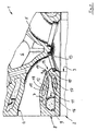
- a liquid-cooled, cast cylinder head 1 of a multi-cylinder, Internal combustion engine 2 (not shown in more detail) includes the cylinder 3 Internal combustion engine 2 a plurality of outlet channels 4 and inlet channels 5 in Cross-flow arrangement with an essentially central arrangement of a Recording dome 6 for a spark plug or an injection nozzle as Operating device of the internal combustion engine 2.
- the valve-controlled gas exchange exhaust duct 4 via a cylinder head-bottom Coolant chamber 7 pressurized coolant, one of which Coolant chamber 7 sectionally delimiting longitudinal side wall 8 of the Cylinder head 1 adjacent to the supply of secondary air serving longitudinal duct 9 is provided with one in the outlet duct 4 opening branch duct 10.
- the branch duct 10 is formed in a strut 12 which connects the outlet duct 4 to the longitudinal side wall 8 or a wall 11 of the longitudinal duct 9 and penetrates the coolant chamber 7.
- the connecting strut 12 arranged according to the invention with coolant is connected to the outlet duct 4 adjacent to an associated valve seat ring 13 in such a way that the connecting strut 12 in a diametrical region 14 compared to an integral arrangement of the outlet duct 4 with the receiving dome 6 with the duct wall 15 of the outlet duct 4 is connected in one piece.
- the longitudinal channel 9 along the exhaust-side longitudinal side wall 8 running on the cylinder head base 16 is arranged, the connecting strut having a branch duct 10 12 to the bottom section of the outlet duct 4 in the Coolant chamber 7 is designed to rise and with both Cylinder head bottom 16 with a coolant flow cross section 17 as well the channel wall 15 limits a coolant flow cross section 18.
- the longitudinal channel 9 is the multi-cylinder Internal combustion engine 2 to avoid crosstalk between the Cylinders 3 divided into sections 9 'and 9 ", each section 9', 9" of a common air pump, not shown, each with valve control Secondary air is supplied
- the downstream of the Valve seat ring 13 adjacent to the inside of the outlet channel 4 opening branch duct 10 upstream of its mouth 19 designed nozzle-like.
- the invention allows for a separate or additional Use of a longitudinal duct with gas discharge inlet ducts Branch channels an intake air-side arrangement of a Exhaust gas recirculation device in the cylinder head or the common arrangement a secondary air supply and an exhaust gas recirculation device in one Cylinder head 1.
- Longitudinal channel 9 or its sections 9 'and 9 "and the branch channels 10 can be made by drilling in the cast cylinder head 1 with considerable effort in additional rework.
- Manufactured cylinder head 1 are each formed by means of a casting core, wherein Extensions to the pouring core of the branch ducts 10 one position-securing intervention in recesses of casting cores Gas exchange channels 4.5 serve.
- the casting cores predetermined Gas exchange channels with comprehensive design a simpler Given handling.
- the task is advantageously solved, with a cross-flow cylinder head 1 with arrangement of a valve-controlled gas exchange channels 4, 5 connected in one piece Recording domes 6 for operating equipment of the internal combustion engine 2 a gas supply channel system consisting of a longitudinal channel and To arrange and form branch channels structurally such that a Deformation of the respective gas exchange channel including an associated one Valve seat ring is at least significantly reduced.
Abstract
Description
Die Erfindung bezieht sich auf einen flüssigkeitsgekühlten, gegossenen Zylinderkopf einer mehrzylindrigen Brennkraftmaschine, der zumindest über zylinderkopf-bodenseitige Kühlmittelkammem kühlmittelbeaufschlagte, ventilgesteuerte Gaswechselkanäle umfasst, wobei einer die Kühlmittelkammern mindestens abschnittsweise begrenzenden Längsseitenwand des Zylinderkopfes benachbart zugeordnet ein gasführender Längskanal vorgesehen ist mit in vorbestimmten Gaswechselkanälen mündenden Abzweigkanälen.The invention relates to a liquid-cooled, cast Cylinder head of a multi-cylinder internal combustion engine, at least over cylinder head-bottom coolant chambers, coolant-loaded, valve-controlled Gas exchange channels, one of which comprises the coolant chambers at least in sections delimiting longitudinal side wall of the A gas-carrying longitudinal channel is assigned adjacent to the cylinder head is provided with branch channels opening into predetermined gas exchange channels.
Bei einem aus der DE 39 34 883 A1 bekannten Zylinderkopf ist der für eine Zuführung von Sekundärluft dienende Längskanal der Längsseitenwand benachbart im Zylinderkopf-Boden ausgebildet. Eine Weiterleitung der Sekundärluft zu einem in einen Abgaskanal mündenden Einblasekanal erfolgt über eine Ausnehmung in einer zwischen Zylinderkopf und einem Maschinengehäuse gepresst angeordneten Zylinderkopf-Dichtung. Der Einblasekanal ist als eine Bohrung gestaltet in einem Wandabschnitt des Zylinderkopfes zwischen einer Brennraummulde und einer Kühlmittelkammer. Diese Anordnung ist mehrfach aufwendig. In a cylinder head known from DE 39 34 883 A1, this is for one Supply of secondary air to the longitudinal duct of the long side wall formed adjacent in the cylinder head base. A forwarding of the Secondary air takes place to an injection duct opening into an exhaust duct via a recess in one between the cylinder head and one Machine housing pressed cylinder head gasket. The Injection channel is designed as a bore in a wall section of the Cylinder head between a combustion chamber trough and a coolant chamber. This arrangement is expensive.
Eine andere Ausgestaltung eines Kanalsystems für eine Sekundärluftzuführung zeigt und beschreibt die DE-OS 2 259 548, wobei ein Längskanal als einseitig offener Kanal in einer auslaßseitigen Längsseitenwand des Zylinderkopfes im Abdeckbereich eines durchgehenden Flansches eines Auspuffkrümmers angeordnet ist und die Sekundärluft über mit dem Längskanal verbundene Stichbohrungen einem jeweiligen Auslasskanal zugeführt ist. Nachteilig hierbei ist die kaum zu beherrschende großflächige Abdichtung.Another embodiment of a duct system for a secondary air supply shows and describes DE-OS 2 259 548, wherein a longitudinal channel as one-sided open channel in an exhaust side longitudinal side wall of the cylinder head in the Cover area of a continuous flange of an exhaust manifold is arranged and the secondary air via connected to the longitudinal channel Stitch bores is supplied to a respective outlet channel. The disadvantage here is the hardly controllable large-area seal.
Weiter sind aus der DE 41 06 499 C1 und der DE-OS2 222 015 jeweils ein Kanalsystem für eine Sekundärluftzuführung mit einem im Zylinderkopf integriert angeordneten Längskanal mit Abzweigkanälen bekannt, deren jeweilige Ausbildung einer freien Anordnung eines Ventiltriebes entgegenstehen kann.Furthermore, each of DE 41 06 499 C1 and DE-OS2 222 015 Channel system for a secondary air supply with one in the cylinder head integrally arranged longitudinal channel with branch channels known, the oppose respective training of a free arrangement of a valve train can.
Dieser Nachteil ist zwar bei dem aus der DE 195 31 875 C1 bekannten Zylinderkopf insofern vermieden, als ein Längskanal für Sekundärluft und ein weiterer Längskanal zur Abgasrückführung eng benachbart in Längsmittenebene des Zylinderkopfes in dessen steuergehäuseseitigen Deckwand angeordnet sind. Gebohrte Einblasekanäle verbinden den einen Längskanal mit Gaswechsel-Einlasskanälen und den anderen Längskanal mit Gaswechsel-Auslasskanälen. Nachteilig hierbei ist die jeweils zusätzliche Gestaltung der jeweiligen Gaswechselkanäle zur Einbringung der in beiden Fällen als Einblaskanäle dienenden Bohrungen. Weiter kompliziert diese bekannte Anordnung von Längskanälen zweier Kanalsysteme für unterschiedliche Zwecke eine Ausbildung von Aufnahmedomen für Zündkerzen oder Einspritzdüsen im Zylinderkopf etwa mittig über dem jeweiligen Brennraum bzw. Zylinder.This disadvantage is true of that known from DE 195 31 875 C1 Avoided cylinder head insofar as a longitudinal channel for secondary air and one further longitudinal duct for exhaust gas recirculation closely adjacent in Longitudinal center plane of the cylinder head in the control housing side Cover wall are arranged. Drilled injection channels connect one Longitudinal channel with gas exchange inlet channels and the other longitudinal channel with Gas exchange outlet passages. The disadvantage here is the additional one Design of the respective gas exchange channels for the introduction of the in both Bores serving as injection channels. This further complicates known arrangement of longitudinal channels of two channel systems for different purposes, training domes for spark plugs or injectors in the cylinder head approximately in the middle above the respective combustion chamber or cylinder.
Schließlich ist ein Zylinderkopf mit den eingangs beschriebenen Gattungsmerkmalen aus der DE 43 44 356 A1 bekannt mit einer in der weiter vorne angegebenen DE 39 34 883 A1 beschriebenen Art der Sekundärluftzuführung, jedoch mit dem Unterschied, dass der Längskanal mit einem Einblasekanal über eine im Zylinderkopf-Boden zwischengeschaltet angeordnete Ausnehmung in Verbindung steht. Der jeweilige Zylinderkopf des gattungsbildenden Dokumentes ist als Querstrom-Zylinderkopf gestaltet mit der Besonderheit, dass im Gegensatz zu modernen Zylinderköpfen anstelle eines jeweiligen Aufnahmedomes für eine Zündkerze oder eine Einspritzdüse eine weitere Kühlmittelkammer angeordnet ist. Damit verbunden ist für die Ventilsitzringe der ventilgesteuerten Gaswechselkanäle jedes Brennraumes in Kombination mit weiteren, den Gaswechselkanälen benachbarten Kühlmittelräumen eine einigermaßen gleichmäßige Temperaturbelastung mit geringer Verformung der Ventilsitzringe.Finally, there is a cylinder head with those described in the introduction Generic features known from DE 43 44 356 A1 with one in the further DE 39 34 883 A1 described above described type of secondary air supply, however with the difference that the longitudinal channel with a Injection channel interposed in the bottom of the cylinder head arranged recess is connected. The respective cylinder head of the The generic document is designed as a cross-flow cylinder head with the Peculiarity that in contrast to modern cylinder heads instead of one respective recording domes for a spark plug or an injection nozzle further coolant chamber is arranged. Associated with that Valve seat rings of the valve-controlled gas exchange channels of each combustion chamber in Combination with other gas exchange channels adjacent Coolant rooms with a reasonably uniform temperature load less deformation of the valve seat rings.
Bei einem je Zylinder mehrventilig ausgebildeten Zylinderkopf mit in Querstromanordnung vorgesehenen Gaswechselventilen mit einem etwa mittig angeordneten Aufnahmedom steht dieser mit den zylinderkopfbodennahen Abschnitten der Gaswechselventile in einstückiger Verbindung. Daraus resultiert das bekannte Problem, dass insbesondere bei einem Auslasskanal aufgrund der hohen Temperaturbelastung in dem der einstückigen Verbindung diametralen Bereich des Auslasskanals eine starke Verformung einschließlich des zugehörigen Ventilsitzringes auftritt.With a multi-valve cylinder head with in Cross flow arrangement provided gas exchange valves with an approximately central arranged dome stands with the cylinder head near the bottom Sections of the gas exchange valves in one piece connection. from that the well-known problem results, in particular with an outlet duct due to the high temperature load in the one-piece connection diametrical area of the exhaust duct including a strong deformation of the associated valve seat ring occurs.
Der Erfindung liegt die Aufgabe zugrunde, bei einem gattungsgemäßen Zylinderkopf mit Anordnung eines zumindest mit einem ventilgesteuerten Gaswechselkanal einstückig verbundenen Aufnahmedomes das einer Gaszuführung dienende Kanalsystem derart strukturell in den Zylinderkopf zu integrieren, dass eine Verformung des Gaswechselkanals im zylinderkopfbodennahen Abschnitt einschließlich seines zugehörigen Ventilsitzringes wesentlich reduziert ist.The invention has for its object in a generic Cylinder head with an arrangement of at least one valve-controlled Gas exchange duct integrally connected recording domes that one Structurally, the gas supply channel system is fed into the cylinder head integrate that a deformation of the gas exchange channel in the section near the cylinder head including its associated Valve seat ring is significantly reduced.
Diese Aufgabe ist mit dem Patentanspruch 1 dadurch gelöst, dass jeder Abzweigkanal in einer den jeweiligen Gaswechselkanal mit der Längsseitenwand des Zylinderkopfes bzw. einer Wandung des Längskanals verbindenden, die jeweilige Kühlmittelkammer durchsetzend angeordneten Strebe ausgebildet ist, wobei die zumindest teilweise kühlmittelbeaufschlagte Verbindungs-Strebe mit dem jeweiligen Gaswechselkanal benachbart eines Ventilsitzringes derart in Verbindung steht, dass die Verbindungs-Strebe im wesentlichen in einem diametralen Bereich einer einstückigen Anordnung von jeweiligem Gaswechselkanal und einem Aufnahmedom für eine Betriebseinrichtung der Brennkraftmaschine mit dem Gaswechselkanal verbunden ist.This object is achieved with claim 1 in that everyone Branch duct in the respective gas exchange duct with the Long side wall of the cylinder head or a wall of the longitudinal channel connecting arranged through the respective coolant chamber Strut is formed, the at least partially acted upon coolant Connection strut with the respective gas exchange channel adjacent one Valve seat ring is connected in such a way that the connecting strut in essentially in a diametrical area of a one-piece arrangement of respective gas exchange channel and a recording dome for one Operating device of the internal combustion engine with the gas exchange channel connected is.
Mit der Erfindung ist in vorteilhafter Weise eine Zylinderkopf-Struktur zur sicheren Vermeidung einer temperaturbedingten Verformung eines jeweiligen Ventilsitzringes erzielt, wobei in weiterer vorteilhafter Weise durch die Beaufschlagung der Verbindungs-Strebe mit dem Kühlmittel einer Verformung des brennraumnahen Gaswechselkanal-Abschnittes und des darin angeordneten Ventilsitzringes zusätzlich entgegengewirkt ist. Mit der Verbindungs-Strebe ergibt sich strukturell eine Anbindung des dem Aufnahmedom diametral gegenüberliegenden Bereiches des Gaswechselkanals an einen steifen Zylinderkopfteil und thermisch eine Wärmeableitung vom Gaswechselkanal mit vergleichmäßigter Temperaturverteilung im Zylinderkopf. Weiter ermöglicht die Erfindung eine freie Gestaltung und Anordnung eines Ventiltriebes im Zylinderkopf.The invention advantageously provides a cylinder head structure for safe avoidance of temperature-related deformation of a particular Valve seat ring achieved, in a further advantageous manner by the Applying the coolant to a deformation of the connecting strut of the gas exchange duct section near the combustion chamber and the one therein arranged valve seat ring is also counteracted. With the Connection strut results in a structural connection of the Recording dome diametrically opposite area of the Gas exchange channel to a rigid cylinder head part and thermally one Heat dissipation from the gas exchange duct with more uniform Temperature distribution in the cylinder head. The invention further enables free design and arrangement of a valve train in the cylinder head.
Für einen beispielsweise aus der DE 38 19 655 C1 bekannten Zylinderkopf mit
einer Querstromanordnung von mehreren Auslasskanälen und Einlasskanälen
mit im wesentlichen mittiger Anordnung eines Aufnahmedomes je Zylinder einer
Brennkraftmaschine ist zur Erzielung einer steifen Struktur bei intensiver
Wärmeableitung aus der jeweiligen Verbindungs-Strebe vorgeschlagen, einen
der Sekundärluftzuführung dienenden Längskanal der auslaßseitigen
Längsseitenwand des Zylinderkopfes bodennah benachbart zuzuordnen, wobei
die je einen Abzweigkanal aufweisenden Verbindungs-Streben zu den
Auslasskanälen in der jeweiligen Kühlmittelkammer jeweils wenigstens
abschnittsweise einen Durchflussquerschnitt mit dem Zylinderkopfboden und
ggf. einen Durchflussquerschnitt mit der Kanalwand des jeweiligen
Auslasskanals begrenzen.
Weiter ist mit der Erfindung die Steifigkeit der Zylinderkopf-Struktur dadurch
gesteigert, dass die Verbindungs-Streben mit der Wandung des Sekundärluft-Längskanals
jeweils über einen mit der Hauptachse zum Längskanal
quergerichteten Querschnitt anschließend ausgebildet sind, und dass die
Verbindungs-Streben über einen demgegenüber sich abflachenden Querschnitt
mit der Kanalwand des jeweiligen Auslasskanals sich über einen vorbestimmten
Umfangsabschnitt im jeweiligen diametralen Bereich erstreckend in einstückiger
Verbindung stehen.For a cylinder head known from DE 38 19 655 C1, for example, with a cross-flow arrangement of a plurality of exhaust ducts and intake ducts with an essentially central arrangement of a receiving dome per cylinder of an internal combustion engine, one of the proposed is to achieve a rigid structure with intensive heat dissipation from the respective connecting strut To assign secondary air supply serving longitudinal channel of the exhaust side longitudinal side wall of the cylinder head near the floor, the connecting struts each having a branch channel to the exhaust ports in the respective coolant chamber each at least in sections defining a flow cross-section with the cylinder head base and possibly a flow cross-section with the channel wall of the respective exhaust port.
Furthermore, the rigidity of the cylinder head structure is increased with the invention in that the connecting struts with the wall of the secondary air longitudinal duct are each formed via a cross-section which is transverse to the main axis to the longitudinal duct, and in that the connecting struts are opposed to one another flattening cross section with the channel wall of the respective outlet channel extending over a predetermined circumferential section in the respective diametrical area in one-piece connection.
Zur Erzielung einer wirkungsvollen Einblasung von Sekundärluft ist jeder stromab des Ventilsitzringes benachbart an der Kanalinnenseite des Auslasskanals mündende Abzweigkanal stromauf seiner Mündung düsenartig gestaltet.Everyone is to achieve an effective injection of secondary air downstream of the valve seat ring adjacent to the inside of the channel Outlet duct opening branch duct upstream of its mouth nozzle-like designed.
Die Erfindung ist gemäß einem weiteren Vorschlag auch für ein einer Abgasrückführung dienendes Kanalsystem dienlich, des weiteren lassen sich beide Kanalsysteme in einem Zylinderkopf verwirklichen.According to a further proposal, the invention is also for one Exhaust gas recirculation duct system useful, furthermore can realize both channel systems in one cylinder head.
Schließlich bezieht sich ein erfindungsgemäßer Vorschlag darauf, dass der Längskanal bzw. seine gegen Übersprechen vorgesehenen Abschnitte mit den zugehörigen Abzweigkanälen in dem mittels eines Gießverfahrens gefertigten Zylinderkopf jeweils mittels eines Gießkernes gebildet sind, wobei Verlängerungen an den Gießkernen der Abzweigkanäle einem lagesichernden Eingriff in Ausnehmungen von Gießkernen der Gaswechselkanäle dienen.Finally, a proposal according to the invention relates to the fact that the Longitudinal channel or its sections provided against crosstalk with the associated branch ducts in the one manufactured by means of a casting process Cylinder head are each formed by means of a casting core, wherein Extensions on the casting cores of the branch ducts to secure the position Serve in recesses in the casting cores of the gas exchange channels.
Diese mehrteilige Kernausbildung ermöglicht gegenüber einer aus der DE 196 35 535 C2 bekannten einteiligen Kerngestaltung , wobei Gießkerne für Längskanal und Abzweigkanäle mit Gießkernen der Auslasskanäle einteilig ausgebildet sind, eine einfachere Handhabung.This multi-part core training enables one from the DE 196 35 535 C2 known one-piece core design, casting cores for Longitudinal duct and branch ducts with casting cores of the outlet ducts in one piece are trained, easier handling.
Die Erfindung ist anhand eines in der Zeichnung gezeigten Ausführungsbeispiels beschrieben. Es zeigt
- Fig.1
- einen abschnittsweisen Querschnitt durch einen Zylinderkopf,
- Fig.2
- einen abschnittsweisen Längsschnitt durch den Zylinderkopf auf Höhe der der Kanäle für eine Sekundärluft-Zuführung.
- Fig.1
- a sectional cross section through a cylinder head,
- Fig.2
- a sectional longitudinal section through the cylinder head at the level of the channels for a secondary air supply.
Ein flüssigkeitsgekühlter, gegossener Zylinderkopf 1 einer mehrzylindrigen,
nicht näher gezeigten Brennkraftmaschine 2 umfasst je Zylinder 3 der
Brennkraftmaschine 2 mehrere Auslasskanäle 4 und Einlasskanäle 5 in
Querstromanordnung mit einer im wesentlichen mittigen Anordnung eines
Aufnahmedomes 6 für eine Zündkerze oder einer Einspritzdüse als
Betriebseinrichtung der Brennkraftmaschine 2 . Wie aus Fig.1 ersichtlich, ist der
ventilgesteuerte Gaswechsel-Auslasskanal 4 über eine zylinderkopf-bodenseitige
Kühlmittelkammer 7 kühlmittelbeaufschlagt, wobei einer die
Kühlmittelkammer 7 abschnittsweise begrenzenden Längsseitenwand 8 des
Zylinderkopfes 1 benachbart zugeordnet ein der Zuführung von Sekundärluft
dienender Längskanal 9 vorgesehen ist mit einem in den Auslasskanal 4
mündenden Abzweigkanal 10.A liquid-cooled, cast cylinder head 1 of a multi-cylinder,
Internal combustion engine 2 (not shown in more detail) includes the
Erfindungsgemäß ist der Abzweigkanal 10 in einer den Auslasskanal 4 mit der
Längsseitenwand 8 bzw. einer Wandung 11 des Längskanals 9 verbindenden ,
die Kühlmittelkammer 7 durchsetzend angeordneten Strebe 12 ausgebildet.
Die erfindungsgemäß kühlmittelbeaufschlagt angeordnete Verbindungs-Strebe
12 steht mit dem Auslasskanal 4 benachbart eines zugehörigen Ventilsitzringes
13 derart in Verbindung, dass die Verbindungs-Strebe 12 in einem diametralen
Bereich 14 gegenüber einer einstückigen Anordnung des Auslasskanals 4 mit
dem Aufnahmedom 6 mit der Kanalwand 15 des Auslasskanals 4 einstückig
verbunden ist.According to the invention, the
The connecting
Weiter ist aus Fig.1 ersichtlich, dass der Längskanal 9 entlang der
auslaßseitigen Längsseitenwand 8 auf dem Zylinderkopf-Boden 16 verlaufend
angeordnet ist, wobei die einen Abzweigkanal 10 aufweisende Verbindungs-Strebe
12 zum bodenseitigen Abschnitt des Auslasskanals 4 in der
Kühlmittelkammer 7 ansteigend ausgebildet ist und sowohl mit dem
Zylinderkopf-Boden 16 einen Kühlmittel-Durchflussquerschnitt 17 als auch mit
der Kanalwand 15 einen Kühlmittel-Durchflussquerschnitt 18 begrenzt.It can also be seen from FIG. 1 that the
Zur Erzielung steifer Anbindungen der Verbindungs-Strebe 12 in ihren beiden
Endbereichen steht diese mit der Wandung 11 des Längskanals 9 über einen
mit der Hauptachse zum Längskanal 9 quergerichteten Querschnitt, d.h. mit
einem hochkant ausgerichteten Querschnitt in Verbindung. Gegenüber diesem
Hochkant-Querschnitt schließt die Verbindungs-Strebe 12 mittels eines
Flachkant-Querschnittes an der Kanalwand 15 des Auslasskanals 4 an, um mit
der Kanalwand 15 über einen vorbestimmten Umfangsabschnitt im diametralen
Bereich in einstückiger Verbindung zu stehen.To achieve rigid connections of the connecting
Wie aus Figur 2 erkennbar, ist der Längskanal 9 der mehrzylindrigen
Brennkraftmaschine 2 zur Vermeidung eines Übersprechens zwischen den
Zylindern 3 in Abschnitte 9'und 9" unterteilt, wobei jeder Abschnitt 9' , 9" von
einer gemeinsamen, nicht gezeigten Luftpumpe jeweils ventilgesteuert mit
Sekundärluft versorgt istAs can be seen from Figure 2, the
Zur Erzielung einer wirkungsvollen Sekundärluft-Einblasung ist der stromab des
Ventilsitzringes 13 benachbart an der Kanalinnenseite des Auslasskanals 4
mündende Abzweigkanal 10 stromauf seiner Mündung 19 düsenartig gestaltet.To achieve an effective secondary air injection, the downstream of the
Valve
Schließlich erlaubt die Erfindung durch eine gesonderte oder zusätzliche Verwendung eines Längskanals mit in Gaswechsel-Einlasskanälen mündenden Abzweigkanälen eine ansaugluftseitige Anordnung einer Abgasrückführeinrichtung im Zylinderkopf oder die gemeinsame Anordnung einer Sekundärluftzuführung und einer Abgasrückführeinrichtung in einem Zylinderkopf 1.Finally, the invention allows for a separate or additional Use of a longitudinal duct with gas discharge inlet ducts Branch channels an intake air-side arrangement of a Exhaust gas recirculation device in the cylinder head or the common arrangement a secondary air supply and an exhaust gas recirculation device in one Cylinder head 1.
Längskanal 9 bzw. seine Abschnitte 9' und 9" sowie die Abzweigkanäle10
können durch Bohren im gegossenen Zylinderkopf 1 hergestellt sein mit
erheblichem Aufwand an zusätzlichen Nacharbeiten. Demgegenüber
vorteilhafter erscheint es, dass der Längskanal 9 bzw. seine Abschnitte 9',9" mit
den zugehörigen Abzweigkanälen 10 in dem mittels eines Gießverfahrens
gefertigten Zylinderkopf 1 jeweils mittels eines Gießkernes gebildet sind, wobei
Verlängerungen an den Gießkemen der Abzweigkanäle 10 einem
lagesichernden Eingriff in Ausnehmungen von Gießkernen der
Gaswechselkanäle 4,5 dienen. Mit dem einteilig ausgebildeten Gießkern für
Längskanal 9 und Abzweigkanälen 10 ist gegenüber der aus der bereits weiter
vorne genannten DE 196 35 535 C2 bekannten, die Gießkerne vorbestimmter
Gaswechselkanäle mitumfassenden Ausgestaltung eine einfachere
Handhabung gegeben.
Mit der vorbeschriebenen Erfindung ist in vorteilhafter Weise die Aufgabe
gelöst, bei einem Querstrom-Zylinderkopf 1 mit Anordnung eines mit
ventilgesteuerten Gaswechselkanälen 4 , 5 einstückig verbundenen
Aufnahmedomes 6 für Betriebseinrichtungen der Brennkraftmaschine 2 das
einer Gaszuführung dienende Kanalsystem aus einem Längskanal und
Abzweigkanälen derart strukturell anzuordnen und auszubilden, dass eine
Verformung des jeweiligen Gaswechselkanals einschließlich eines zugehörigen
Ventilsitzringes zumindest wesentlich reduziert ist.With the above-described invention, the task is advantageously
solved, with a cross-flow cylinder head 1 with arrangement of a
valve-controlled
Claims (7)
Applications Claiming Priority (2)
| Application Number | Priority Date | Filing Date | Title |
|---|---|---|---|
| DE10257064A DE10257064A1 (en) | 2002-12-06 | 2002-12-06 | Liquid-cooled, cast cylinder head of a multi-cylinder internal combustion engine |
| DE10257064 | 2002-12-06 |
Publications (2)
| Publication Number | Publication Date |
|---|---|
| EP1426600A1 true EP1426600A1 (en) | 2004-06-09 |
| EP1426600B1 EP1426600B1 (en) | 2009-08-26 |
Family
ID=32309018
Family Applications (1)
| Application Number | Title | Priority Date | Filing Date |
|---|---|---|---|
| EP03023802A Expired - Lifetime EP1426600B1 (en) | 2002-12-06 | 2003-10-17 | Casted, liquid-cooled cylinder head of a multi-cylinder internal combustion engine |
Country Status (2)
| Country | Link |
|---|---|
| EP (1) | EP1426600B1 (en) |
| DE (2) | DE10257064A1 (en) |
Cited By (1)
| Publication number | Priority date | Publication date | Assignee | Title |
|---|---|---|---|---|
| CN101333974B (en) * | 2007-05-04 | 2013-11-06 | Gm全球科技运作股份有限公司 | Cylinder head and production method for a cylinder head |
Citations (5)
| Publication number | Priority date | Publication date | Assignee | Title |
|---|---|---|---|---|
| DE1576779A1 (en) * | 1967-03-08 | 1970-03-19 | Nallinger Dr Ing Friedrich | Internal combustion engine |
| US4119071A (en) * | 1976-09-17 | 1978-10-10 | Toyota Jidosha Kogyo Kabushiki Kaisha | Exhaust gas recirculating device in an internal combustion engine |
| DE3802886A1 (en) * | 1987-02-04 | 1988-08-18 | Avl Verbrennungskraft Messtech | Cylinder head for water-cooled internal combustion engines |
| US6327853B1 (en) * | 1998-09-02 | 2001-12-11 | Honda Giken Kogyo Kabushiki Kaisha | Structure for introducing secondary air into exhaust path of internal combustion engine |
| DE10040120A1 (en) * | 2000-08-17 | 2002-02-28 | Daimler Chrysler Ag | Cylinder head for internal combustion engine has recesses that are formed in series along outlet channels and are connected with at least two outlet channels |
Family Cites Families (18)
| Publication number | Priority date | Publication date | Assignee | Title |
|---|---|---|---|---|
| GB1442247A (en) * | 1973-09-06 | 1976-07-14 | Daimler Benz Ag | Fou-stroke internal-combustion engine |
| JPS5445224Y2 (en) * | 1975-08-18 | 1979-12-25 | ||
| US4018195A (en) * | 1975-10-06 | 1977-04-19 | General Motors Corporation | Insulated, high efficiency, low heat rejection, engine cylinder head |
| US4184328A (en) * | 1977-09-08 | 1980-01-22 | Teledyne Industries, Inc. | Air cooled exhaust valve |
| JPS619138Y2 (en) * | 1980-12-12 | 1986-03-22 | ||
| US4454714A (en) * | 1980-12-26 | 1984-06-19 | Honda Giken Kogyo Kabushiki Kaisha | Exhaust gas cleaning device for internal combustion engines |
| JPS58106119A (en) * | 1981-12-17 | 1983-06-24 | Honda Motor Co Ltd | Exhaust purifier in internal-combustion engine |
| US4604865A (en) * | 1982-04-24 | 1986-08-12 | Honda Giken Kogyo Kabushiki Kaisha | Exhaust system air introduction device |
| US5761904A (en) * | 1994-03-28 | 1998-06-09 | Honda Giken Kogyo Kabushiki Kaisha | Air inlet structure for exhaust passage in engine |
| DE4435555C1 (en) * | 1994-10-05 | 1996-03-14 | Porsche Ag | Multi-cylinder internal combustion engine |
| DE19802060A1 (en) * | 1998-01-21 | 1999-07-22 | Bayerische Motoren Werke Ag | Liquid-cooled cylinder head of a multi-cylinder, multi-valve internal combustion engine |
| DE19849113A1 (en) * | 1998-10-24 | 2000-05-04 | Daimler Chrysler Ag | Fuel delivery system for externally ignited internal combustion engine has channel formed in cylinder head in which gaseous medium can flow to injection valves |
| JP4093512B2 (en) * | 1998-11-25 | 2008-06-04 | 本田技研工業株式会社 | Secondary air supply device for engine exhaust |
| DE19902678C2 (en) * | 1999-01-23 | 2001-11-15 | Audi Ag | Multi-cylinder internal combustion engine |
| DE19919642C2 (en) * | 1999-04-30 | 2002-12-05 | Daimler Chrysler Ag | Device for igniting fuel in the shift-operated gasoline engine |
| DE19956825C1 (en) * | 1999-11-25 | 2001-02-08 | Porsche Ag | Cylinder head for an IC motor has a head system with valves at the same angle for a variant with fuel intake and a variant for direct fuel injection as a common head for either type |
| DE10003955A1 (en) * | 2000-01-29 | 2001-08-02 | Porsche Ag | Secondary air feed for internal combustion engines has twin flow exhaust pipe connected to cylinder head by two separate flange arrangements, and has distribution passage for secondary air with two independent longitudinal sections |
| JP3579643B2 (en) * | 2000-10-13 | 2004-10-20 | 本田技研工業株式会社 | Engine cylinder head |
-
2002
- 2002-12-06 DE DE10257064A patent/DE10257064A1/en not_active Withdrawn
-
2003
- 2003-10-17 DE DE50311844T patent/DE50311844D1/en not_active Expired - Lifetime
- 2003-10-17 EP EP03023802A patent/EP1426600B1/en not_active Expired - Lifetime
Patent Citations (5)
| Publication number | Priority date | Publication date | Assignee | Title |
|---|---|---|---|---|
| DE1576779A1 (en) * | 1967-03-08 | 1970-03-19 | Nallinger Dr Ing Friedrich | Internal combustion engine |
| US4119071A (en) * | 1976-09-17 | 1978-10-10 | Toyota Jidosha Kogyo Kabushiki Kaisha | Exhaust gas recirculating device in an internal combustion engine |
| DE3802886A1 (en) * | 1987-02-04 | 1988-08-18 | Avl Verbrennungskraft Messtech | Cylinder head for water-cooled internal combustion engines |
| US6327853B1 (en) * | 1998-09-02 | 2001-12-11 | Honda Giken Kogyo Kabushiki Kaisha | Structure for introducing secondary air into exhaust path of internal combustion engine |
| DE10040120A1 (en) * | 2000-08-17 | 2002-02-28 | Daimler Chrysler Ag | Cylinder head for internal combustion engine has recesses that are formed in series along outlet channels and are connected with at least two outlet channels |
Cited By (1)
| Publication number | Priority date | Publication date | Assignee | Title |
|---|---|---|---|---|
| CN101333974B (en) * | 2007-05-04 | 2013-11-06 | Gm全球科技运作股份有限公司 | Cylinder head and production method for a cylinder head |
Also Published As
| Publication number | Publication date |
|---|---|
| EP1426600B1 (en) | 2009-08-26 |
| DE10257064A1 (en) | 2004-06-24 |
| DE50311844D1 (en) | 2009-10-08 |
Similar Documents
| Publication | Publication Date | Title |
|---|---|---|
| DE10202661B4 (en) | Cylinder head for several cylinders | |
| EP1126152B1 (en) | Cylinder head for an internal combustion engine | |
| AT506473B1 (en) | CYLINDER HEAD OF AN INTERNAL COMBUSTION ENGINE | |
| DE102005026599B4 (en) | Internal combustion engine | |
| EP3379063B1 (en) | Liquid-cooled combustion engine | |
| DE1292938B (en) | Cylinder head for a piston internal combustion engine with self-ignition | |
| DE102007062347B4 (en) | Cooling arrangement for a cylinder head of an internal combustion engine | |
| DE102008047185A1 (en) | Cooling agent flow path arrangement for cylinder head of internal-combustion engine, has partial flow path with path region assigned to valve, and another partial flow path with path section assigned to spark plug or diesel injector | |
| DE112007000918B4 (en) | Cylinder head for an engine and engine | |
| DE10331918B4 (en) | Cylinder head for a liquid-cooled multi-cylinder internal combustion engine | |
| EP0062143A2 (en) | Cylinder head for an air-compressed auto-ignition and injection engine | |
| EP1972772B1 (en) | Cylinder head for a fluid-cooled combustion engine | |
| EP3615783B1 (en) | Cylinder head housing, method for producing a cylinder head housing, and casting core | |
| EP1329628B1 (en) | Cylinder head for a piston combustion engine with a cooling conduit system | |
| DE3545333C2 (en) | ||
| DE102010030793A1 (en) | Reflection of cylinder heads | |
| EP1426600A1 (en) | Casted, liquid-cooled cylinder head of a multi-cylinder internal combustion engine | |
| AT524566B1 (en) | Liquid-cooled internal combustion engine | |
| AT524536B1 (en) | LIQUID-COOLED INTERNAL ENGINE | |
| DE102009044158B4 (en) | Cylinder head of an internal combustion engine with a cooling channel between the ignition device and the injection device | |
| DE102015202491B4 (en) | Coolant jacket for a cylinder head of an internal combustion engine | |
| DE3934883A1 (en) | IC engine with air injection device - has connected distributor tube and injection tube | |
| AT413860B (en) | CYLINDER HEAD FOR A LIQUID-COOLED MULTI-CYLINDER INTERNAL COMBUSTION ENGINE | |
| DE112020000203T5 (en) | Heat shield system and procedures | |
| WO2014086489A1 (en) | Internal combustion engine |
Legal Events
| Date | Code | Title | Description |
|---|---|---|---|
| PUAI | Public reference made under article 153(3) epc to a published international application that has entered the european phase |
Free format text: ORIGINAL CODE: 0009012 |
|
| AK | Designated contracting states |
Kind code of ref document: A1 Designated state(s): AT BE BG CH CY CZ DE DK EE ES FI FR GB GR HU IE IT LI LU MC NL PT RO SE SI SK TR |
|
| AX | Request for extension of the european patent |
Extension state: AL LT LV MK |
|
| 17P | Request for examination filed |
Effective date: 20040626 |
|
| AKX | Designation fees paid |
Designated state(s): DE ES FR GB IT |
|
| 17Q | First examination report despatched |
Effective date: 20080409 |
|
| GRAP | Despatch of communication of intention to grant a patent |
Free format text: ORIGINAL CODE: EPIDOSNIGR1 |
|
| GRAS | Grant fee paid |
Free format text: ORIGINAL CODE: EPIDOSNIGR3 |
|
| GRAA | (expected) grant |
Free format text: ORIGINAL CODE: 0009210 |
|
| AK | Designated contracting states |
Kind code of ref document: B1 Designated state(s): DE ES FR GB IT |
|
| REG | Reference to a national code |
Ref country code: GB Ref legal event code: FG4D Free format text: NOT ENGLISH |
|
| REF | Corresponds to: |
Ref document number: 50311844 Country of ref document: DE Date of ref document: 20091008 Kind code of ref document: P |
|
| PG25 | Lapsed in a contracting state [announced via postgrant information from national office to epo] |
Ref country code: ES Free format text: LAPSE BECAUSE OF FAILURE TO SUBMIT A TRANSLATION OF THE DESCRIPTION OR TO PAY THE FEE WITHIN THE PRESCRIBED TIME-LIMIT Effective date: 20091207 |
|
| PLBE | No opposition filed within time limit |
Free format text: ORIGINAL CODE: 0009261 |
|
| STAA | Information on the status of an ep patent application or granted ep patent |
Free format text: STATUS: NO OPPOSITION FILED WITHIN TIME LIMIT |
|
| 26N | No opposition filed |
Effective date: 20100527 |
|
| PG25 | Lapsed in a contracting state [announced via postgrant information from national office to epo] |
Ref country code: IT Free format text: LAPSE BECAUSE OF FAILURE TO SUBMIT A TRANSLATION OF THE DESCRIPTION OR TO PAY THE FEE WITHIN THE PRESCRIBED TIME-LIMIT Effective date: 20090826 |
|
| REG | Reference to a national code |
Ref country code: FR Ref legal event code: PLFP Year of fee payment: 13 |
|
| REG | Reference to a national code |
Ref country code: FR Ref legal event code: PLFP Year of fee payment: 14 |
|
| REG | Reference to a national code |
Ref country code: FR Ref legal event code: PLFP Year of fee payment: 15 |
|
| REG | Reference to a national code |
Ref country code: FR Ref legal event code: PLFP Year of fee payment: 16 |
|
| PGFP | Annual fee paid to national office [announced via postgrant information from national office to epo] |
Ref country code: DE Payment date: 20191019 Year of fee payment: 17 |
|
| PGFP | Annual fee paid to national office [announced via postgrant information from national office to epo] |
Ref country code: GB Payment date: 20201022 Year of fee payment: 18 Ref country code: FR Payment date: 20201020 Year of fee payment: 18 |
|
| REG | Reference to a national code |
Ref country code: DE Ref legal event code: R119 Ref document number: 50311844 Country of ref document: DE |
|
| PG25 | Lapsed in a contracting state [announced via postgrant information from national office to epo] |
Ref country code: DE Free format text: LAPSE BECAUSE OF NON-PAYMENT OF DUE FEES Effective date: 20210501 |
|
| GBPC | Gb: european patent ceased through non-payment of renewal fee |
Effective date: 20211017 |
|
| PG25 | Lapsed in a contracting state [announced via postgrant information from national office to epo] |
Ref country code: GB Free format text: LAPSE BECAUSE OF NON-PAYMENT OF DUE FEES Effective date: 20211017 |
|
| PG25 | Lapsed in a contracting state [announced via postgrant information from national office to epo] |
Ref country code: FR Free format text: LAPSE BECAUSE OF NON-PAYMENT OF DUE FEES Effective date: 20211031 |