EP1426600A1 - Culasse moulée, refroidie par liquide, pour un moteur à combustion interne à plusieurs cylindres - Google Patents
Culasse moulée, refroidie par liquide, pour un moteur à combustion interne à plusieurs cylindres Download PDFInfo
- Publication number
- EP1426600A1 EP1426600A1 EP03023802A EP03023802A EP1426600A1 EP 1426600 A1 EP1426600 A1 EP 1426600A1 EP 03023802 A EP03023802 A EP 03023802A EP 03023802 A EP03023802 A EP 03023802A EP 1426600 A1 EP1426600 A1 EP 1426600A1
- Authority
- EP
- European Patent Office
- Prior art keywords
- cylinder head
- duct
- gas exchange
- longitudinal
- branch
- Prior art date
- Legal status (The legal status is an assumption and is not a legal conclusion. Google has not performed a legal analysis and makes no representation as to the accuracy of the status listed.)
- Granted
Links
Images

Classifications
-
- F—MECHANICAL ENGINEERING; LIGHTING; HEATING; WEAPONS; BLASTING
- F01—MACHINES OR ENGINES IN GENERAL; ENGINE PLANTS IN GENERAL; STEAM ENGINES
- F01N—GAS-FLOW SILENCERS OR EXHAUST APPARATUS FOR MACHINES OR ENGINES IN GENERAL; GAS-FLOW SILENCERS OR EXHAUST APPARATUS FOR INTERNAL COMBUSTION ENGINES
- F01N3/00—Exhaust or silencing apparatus having means for purifying, rendering innocuous, or otherwise treating exhaust
- F01N3/08—Exhaust or silencing apparatus having means for purifying, rendering innocuous, or otherwise treating exhaust for rendering innocuous
- F01N3/10—Exhaust or silencing apparatus having means for purifying, rendering innocuous, or otherwise treating exhaust for rendering innocuous by thermal or catalytic conversion of noxious components of exhaust
- F01N3/24—Exhaust or silencing apparatus having means for purifying, rendering innocuous, or otherwise treating exhaust for rendering innocuous by thermal or catalytic conversion of noxious components of exhaust characterised by constructional aspects of converting apparatus
- F01N3/30—Arrangements for supply of additional air
- F01N3/34—Arrangements for supply of additional air using air conduits or jet air pumps, e.g. near the engine exhaust port
-
- F—MECHANICAL ENGINEERING; LIGHTING; HEATING; WEAPONS; BLASTING
- F02—COMBUSTION ENGINES; HOT-GAS OR COMBUSTION-PRODUCT ENGINE PLANTS
- F02F—CYLINDERS, PISTONS OR CASINGS, FOR COMBUSTION ENGINES; ARRANGEMENTS OF SEALINGS IN COMBUSTION ENGINES
- F02F1/00—Cylinders; Cylinder heads
- F02F1/24—Cylinder heads
- F02F1/26—Cylinder heads having cooling means
- F02F1/36—Cylinder heads having cooling means for liquid cooling
- F02F1/38—Cylinder heads having cooling means for liquid cooling the cylinder heads being of overhead valve type
-
- F—MECHANICAL ENGINEERING; LIGHTING; HEATING; WEAPONS; BLASTING
- F02—COMBUSTION ENGINES; HOT-GAS OR COMBUSTION-PRODUCT ENGINE PLANTS
- F02F—CYLINDERS, PISTONS OR CASINGS, FOR COMBUSTION ENGINES; ARRANGEMENTS OF SEALINGS IN COMBUSTION ENGINES
- F02F1/00—Cylinders; Cylinder heads
- F02F1/24—Cylinder heads
- F02F1/42—Shape or arrangement of intake or exhaust channels in cylinder heads
- F02F1/4214—Shape or arrangement of intake or exhaust channels in cylinder heads specially adapted for four or more valves per cylinder
-
- F—MECHANICAL ENGINEERING; LIGHTING; HEATING; WEAPONS; BLASTING
- F02—COMBUSTION ENGINES; HOT-GAS OR COMBUSTION-PRODUCT ENGINE PLANTS
- F02F—CYLINDERS, PISTONS OR CASINGS, FOR COMBUSTION ENGINES; ARRANGEMENTS OF SEALINGS IN COMBUSTION ENGINES
- F02F2200/00—Manufacturing
- F02F2200/06—Casting
-
- Y—GENERAL TAGGING OF NEW TECHNOLOGICAL DEVELOPMENTS; GENERAL TAGGING OF CROSS-SECTIONAL TECHNOLOGIES SPANNING OVER SEVERAL SECTIONS OF THE IPC; TECHNICAL SUBJECTS COVERED BY FORMER USPC CROSS-REFERENCE ART COLLECTIONS [XRACs] AND DIGESTS
- Y02—TECHNOLOGIES OR APPLICATIONS FOR MITIGATION OR ADAPTATION AGAINST CLIMATE CHANGE
- Y02T—CLIMATE CHANGE MITIGATION TECHNOLOGIES RELATED TO TRANSPORTATION
- Y02T10/00—Road transport of goods or passengers
- Y02T10/10—Internal combustion engine [ICE] based vehicles
- Y02T10/12—Improving ICE efficiencies
Definitions
- the invention relates to a liquid-cooled, cast Cylinder head of a multi-cylinder internal combustion engine, at least over cylinder head-bottom coolant chambers, coolant-loaded, valve-controlled Gas exchange channels, one of which comprises the coolant chambers at least in sections delimiting longitudinal side wall of the A gas-carrying longitudinal channel is assigned adjacent to the cylinder head is provided with branch channels opening into predetermined gas exchange channels.
- a cylinder head known from DE 39 34 883 A1
- this is for one Supply of secondary air to the longitudinal duct of the long side wall formed adjacent in the cylinder head base.
- a forwarding of the Secondary air takes place to an injection duct opening into an exhaust duct via a recess in one between the cylinder head and one Machine housing pressed cylinder head gasket.
- the Injection channel is designed as a bore in a wall section of the Cylinder head between a combustion chamber trough and a coolant chamber. This arrangement is expensive.
- a duct system for a secondary air supply shows and describes DE-OS 2 259 548, wherein a longitudinal channel as one-sided open channel in an exhaust side longitudinal side wall of the cylinder head in the Cover area of a continuous flange of an exhaust manifold is arranged and the secondary air via connected to the longitudinal channel Stitch bores is supplied to a respective outlet channel.
- the disadvantage here is the hardly controllable large-area seal.
- the invention has for its object in a generic Cylinder head with an arrangement of at least one valve-controlled Gas exchange duct integrally connected recording domes that one Structurally, the gas supply channel system is fed into the cylinder head integrate that a deformation of the gas exchange channel in the section near the cylinder head including its associated Valve seat ring is significantly reduced.
- the invention advantageously provides a cylinder head structure for safe avoidance of temperature-related deformation of a particular Valve seat ring achieved, in a further advantageous manner by the Applying the coolant to a deformation of the connecting strut of the gas exchange duct section near the combustion chamber and the one therein arranged valve seat ring is also counteracted.
- the Connection strut results in a structural connection of the Recording dome diametrically opposite area of the Gas exchange channel to a rigid cylinder head part and thermally one Heat dissipation from the gas exchange duct with more uniform Temperature distribution in the cylinder head.
- the invention further enables free design and arrangement of a valve train in the cylinder head.
- the connecting struts each having a branch channel to the exhaust ports in the respective coolant chamber each at least in sections defining a flow cross-section with the cylinder head base and possibly a flow cross-section with the channel wall of the respective exhaust port.
- the rigidity of the cylinder head structure is increased with the invention in that the connecting struts with the wall of the secondary air longitudinal duct are each formed via a cross-section which is transverse to the main axis to the longitudinal duct, and in that the connecting struts are opposed to one another flattening cross section with the channel wall of the respective outlet channel extending over a predetermined circumferential section in the respective diametrical area in one-piece connection.
- the invention is also for one Exhaust gas recirculation duct system useful, furthermore can realize both channel systems in one cylinder head.
- a proposal according to the invention relates to the fact that the Longitudinal channel or its sections provided against crosstalk with the associated branch ducts in the one manufactured by means of a casting process Cylinder head are each formed by means of a casting core, wherein Extensions on the casting cores of the branch ducts to secure the position Serve in recesses in the casting cores of the gas exchange channels.
- This multi-part core training enables one from the DE 196 35 535 C2 known one-piece core design, casting cores for Longitudinal duct and branch ducts with casting cores of the outlet ducts in one piece are trained, easier handling.
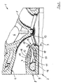
- a liquid-cooled, cast cylinder head 1 of a multi-cylinder, Internal combustion engine 2 (not shown in more detail) includes the cylinder 3 Internal combustion engine 2 a plurality of outlet channels 4 and inlet channels 5 in Cross-flow arrangement with an essentially central arrangement of a Recording dome 6 for a spark plug or an injection nozzle as Operating device of the internal combustion engine 2.
- the valve-controlled gas exchange exhaust duct 4 via a cylinder head-bottom Coolant chamber 7 pressurized coolant, one of which Coolant chamber 7 sectionally delimiting longitudinal side wall 8 of the Cylinder head 1 adjacent to the supply of secondary air serving longitudinal duct 9 is provided with one in the outlet duct 4 opening branch duct 10.
- the branch duct 10 is formed in a strut 12 which connects the outlet duct 4 to the longitudinal side wall 8 or a wall 11 of the longitudinal duct 9 and penetrates the coolant chamber 7.
- the connecting strut 12 arranged according to the invention with coolant is connected to the outlet duct 4 adjacent to an associated valve seat ring 13 in such a way that the connecting strut 12 in a diametrical region 14 compared to an integral arrangement of the outlet duct 4 with the receiving dome 6 with the duct wall 15 of the outlet duct 4 is connected in one piece.
- the longitudinal channel 9 along the exhaust-side longitudinal side wall 8 running on the cylinder head base 16 is arranged, the connecting strut having a branch duct 10 12 to the bottom section of the outlet duct 4 in the Coolant chamber 7 is designed to rise and with both Cylinder head bottom 16 with a coolant flow cross section 17 as well the channel wall 15 limits a coolant flow cross section 18.
- the longitudinal channel 9 is the multi-cylinder Internal combustion engine 2 to avoid crosstalk between the Cylinders 3 divided into sections 9 'and 9 ", each section 9', 9" of a common air pump, not shown, each with valve control Secondary air is supplied
- the downstream of the Valve seat ring 13 adjacent to the inside of the outlet channel 4 opening branch duct 10 upstream of its mouth 19 designed nozzle-like.
- the invention allows for a separate or additional Use of a longitudinal duct with gas discharge inlet ducts Branch channels an intake air-side arrangement of a Exhaust gas recirculation device in the cylinder head or the common arrangement a secondary air supply and an exhaust gas recirculation device in one Cylinder head 1.
- Longitudinal channel 9 or its sections 9 'and 9 "and the branch channels 10 can be made by drilling in the cast cylinder head 1 with considerable effort in additional rework.
- Manufactured cylinder head 1 are each formed by means of a casting core, wherein Extensions to the pouring core of the branch ducts 10 one position-securing intervention in recesses of casting cores Gas exchange channels 4.5 serve.
- the casting cores predetermined Gas exchange channels with comprehensive design a simpler Given handling.
- the task is advantageously solved, with a cross-flow cylinder head 1 with arrangement of a valve-controlled gas exchange channels 4, 5 connected in one piece Recording domes 6 for operating equipment of the internal combustion engine 2 a gas supply channel system consisting of a longitudinal channel and To arrange and form branch channels structurally such that a Deformation of the respective gas exchange channel including an associated one Valve seat ring is at least significantly reduced.
Applications Claiming Priority (2)
| Application Number | Priority Date | Filing Date | Title |
|---|---|---|---|
| DE10257064A DE10257064A1 (de) | 2002-12-06 | 2002-12-06 | Flüssigkeitsgekühlter, gegossener Zylinderkopf einer mehrzylindrigen Brennkraftmaschine |
| DE10257064 | 2002-12-06 |
Publications (2)
| Publication Number | Publication Date |
|---|---|
| EP1426600A1 true EP1426600A1 (fr) | 2004-06-09 |
| EP1426600B1 EP1426600B1 (fr) | 2009-08-26 |
Family
ID=32309018
Family Applications (1)
| Application Number | Title | Priority Date | Filing Date |
|---|---|---|---|
| EP03023802A Expired - Lifetime EP1426600B1 (fr) | 2002-12-06 | 2003-10-17 | Culasse moulée, refroidie par liquide, pour un moteur à combustion interne à plusieurs cylindres |
Country Status (2)
| Country | Link |
|---|---|
| EP (1) | EP1426600B1 (fr) |
| DE (2) | DE10257064A1 (fr) |
Cited By (1)
| Publication number | Priority date | Publication date | Assignee | Title |
|---|---|---|---|---|
| CN101333974B (zh) * | 2007-05-04 | 2013-11-06 | Gm全球科技运作股份有限公司 | 气缸盖及其制造方法 |
Citations (5)
| Publication number | Priority date | Publication date | Assignee | Title |
|---|---|---|---|---|
| DE1576779A1 (de) * | 1967-03-08 | 1970-03-19 | Nallinger Dr Ing Friedrich | Verbrennungskraftmaschine |
| US4119071A (en) * | 1976-09-17 | 1978-10-10 | Toyota Jidosha Kogyo Kabushiki Kaisha | Exhaust gas recirculating device in an internal combustion engine |
| DE3802886A1 (de) * | 1987-02-04 | 1988-08-18 | Avl Verbrennungskraft Messtech | Zylinderkopf fuer wassergekuehlte brennkraftmaschinen |
| US6327853B1 (en) * | 1998-09-02 | 2001-12-11 | Honda Giken Kogyo Kabushiki Kaisha | Structure for introducing secondary air into exhaust path of internal combustion engine |
| DE10040120A1 (de) * | 2000-08-17 | 2002-02-28 | Daimler Chrysler Ag | Zylinderkopf für eine Brennkraftmaschine |
Family Cites Families (18)
| Publication number | Priority date | Publication date | Assignee | Title |
|---|---|---|---|---|
| GB1442247A (en) * | 1973-09-06 | 1976-07-14 | Daimler Benz Ag | Fou-stroke internal-combustion engine |
| JPS5445224Y2 (fr) * | 1975-08-18 | 1979-12-25 | ||
| US4018195A (en) * | 1975-10-06 | 1977-04-19 | General Motors Corporation | Insulated, high efficiency, low heat rejection, engine cylinder head |
| US4184328A (en) * | 1977-09-08 | 1980-01-22 | Teledyne Industries, Inc. | Air cooled exhaust valve |
| JPS619138Y2 (fr) * | 1980-12-12 | 1986-03-22 | ||
| US4454714A (en) * | 1980-12-26 | 1984-06-19 | Honda Giken Kogyo Kabushiki Kaisha | Exhaust gas cleaning device for internal combustion engines |
| JPS58106119A (ja) * | 1981-12-17 | 1983-06-24 | Honda Motor Co Ltd | 内燃機関における排気浄化装置 |
| US4604865A (en) * | 1982-04-24 | 1986-08-12 | Honda Giken Kogyo Kabushiki Kaisha | Exhaust system air introduction device |
| US5761904A (en) * | 1994-03-28 | 1998-06-09 | Honda Giken Kogyo Kabushiki Kaisha | Air inlet structure for exhaust passage in engine |
| DE4435555C1 (de) * | 1994-10-05 | 1996-03-14 | Porsche Ag | Mehrzylindrige Brennkraftmaschine |
| DE19802060A1 (de) * | 1998-01-21 | 1999-07-22 | Bayerische Motoren Werke Ag | Flüssigkeitsgekühlter Zylinderkopf einer mehrzylindrigen, je Zylinder mehrventiligen Brennkraftmaschine |
| DE19849113A1 (de) * | 1998-10-24 | 2000-05-04 | Daimler Chrysler Ag | Brennstoffzuführsystem für eine fremdgezündete Brennkraftmaschine |
| JP4093512B2 (ja) * | 1998-11-25 | 2008-06-04 | 本田技研工業株式会社 | エンジンの排気用二次空気供給装置 |
| DE19902678C2 (de) * | 1999-01-23 | 2001-11-15 | Audi Ag | Mehrzylindrige Brennkraftmaschine |
| DE19919642C2 (de) * | 1999-04-30 | 2002-12-05 | Daimler Chrysler Ag | Vorrichtung zum Zünden von Kraftstoff beim schichtbetriebenen Ottomotor |
| DE19956825C1 (de) * | 1999-11-25 | 2001-02-08 | Porsche Ag | Zylinderkopf für eine Brennkraftmaschine |
| DE10003955A1 (de) * | 2000-01-29 | 2001-08-02 | Porsche Ag | Sekundärluftzuführung für Brennkraftmaschinen |
| JP3579643B2 (ja) * | 2000-10-13 | 2004-10-20 | 本田技研工業株式会社 | エンジンのシリンダヘッド |
-
2002
- 2002-12-06 DE DE10257064A patent/DE10257064A1/de not_active Withdrawn
-
2003
- 2003-10-17 EP EP03023802A patent/EP1426600B1/fr not_active Expired - Lifetime
- 2003-10-17 DE DE50311844T patent/DE50311844D1/de not_active Expired - Lifetime
Patent Citations (5)
| Publication number | Priority date | Publication date | Assignee | Title |
|---|---|---|---|---|
| DE1576779A1 (de) * | 1967-03-08 | 1970-03-19 | Nallinger Dr Ing Friedrich | Verbrennungskraftmaschine |
| US4119071A (en) * | 1976-09-17 | 1978-10-10 | Toyota Jidosha Kogyo Kabushiki Kaisha | Exhaust gas recirculating device in an internal combustion engine |
| DE3802886A1 (de) * | 1987-02-04 | 1988-08-18 | Avl Verbrennungskraft Messtech | Zylinderkopf fuer wassergekuehlte brennkraftmaschinen |
| US6327853B1 (en) * | 1998-09-02 | 2001-12-11 | Honda Giken Kogyo Kabushiki Kaisha | Structure for introducing secondary air into exhaust path of internal combustion engine |
| DE10040120A1 (de) * | 2000-08-17 | 2002-02-28 | Daimler Chrysler Ag | Zylinderkopf für eine Brennkraftmaschine |
Cited By (1)
| Publication number | Priority date | Publication date | Assignee | Title |
|---|---|---|---|---|
| CN101333974B (zh) * | 2007-05-04 | 2013-11-06 | Gm全球科技运作股份有限公司 | 气缸盖及其制造方法 |
Also Published As
| Publication number | Publication date |
|---|---|
| DE10257064A1 (de) | 2004-06-24 |
| DE50311844D1 (de) | 2009-10-08 |
| EP1426600B1 (fr) | 2009-08-26 |
Similar Documents
| Publication | Publication Date | Title |
|---|---|---|
| DE10202661B4 (de) | Zylinderkopf für mehrere Zylinder | |
| EP1126152B1 (fr) | Culasse pour un moteur à combustion interne | |
| AT506473B1 (de) | Zylinderkopf einer brennkraftmaschine | |
| DE102005026599B4 (de) | Brennkraftmaschine | |
| EP3379063B1 (fr) | Moteur à combustion interne à refroidissement par liquide | |
| DE1292938B (de) | Zylinderkopf fuer eine Kolbenbrennkraftmaschine mit Selbstzuendung | |
| DE102007062347B4 (de) | Kühlanordnung für einen Zylinderkopf einer Brennkraftmaschine | |
| DE102008047185A1 (de) | Kühlmittelströmungsweganordnung eines Zylinderkopfes einer Brennkraftmaschine und Verfahren zu dessen Kühlung | |
| DE112007000918B4 (de) | Zylinderkopf für einen Motor sowie Motor | |
| DE10331918B4 (de) | Zylinderkopf für eine flüssigkeitsgekühlte Mehrzylinder-Brennkraftmaschine | |
| EP0062143A2 (fr) | Culasse de cylindres pour un moteur à compression d'air, à auto-allumage et à injection | |
| EP1972772B1 (fr) | Culasse pour un moteur à combustion interne refroidi par liquide | |
| EP3615783B1 (fr) | Boîtier de culasse, procédé pour la fabrication d'un boîtier de culasse et noyau de coulée | |
| EP1329628B1 (fr) | Culasse pour un moteur à combustion à pistons avec un système de canaux de refroidissement | |
| DE3545333C2 (fr) | ||
| DE102010030793A1 (de) | Spiegelbild-Zylinderköpfe | |
| EP1426600A1 (fr) | Culasse moulée, refroidie par liquide, pour un moteur à combustion interne à plusieurs cylindres | |
| AT524566B1 (de) | Flüssigkeitsgekühlte Brennkraftmaschine | |
| AT524536B1 (de) | Flüssigkeitsgekühlte brennkraftmaschine | |
| DE102009044158B4 (de) | Zylinderkopf einer Brennkraftmaschine mit einem Kühlkanal zwischen der Zündeinrichtung und der Einspritzeinrichtung | |
| DE102015202491B4 (de) | Kühlmittelmantel für einen Zylinderkopf einer Brennkraftmaschine | |
| DE3934883A1 (de) | Brennkraftmaschine mit einer einblasevorrichtung in einen gaswechselkanal, insbesondere zum lufteinblasen in einen abgaskanal | |
| AT413860B (de) | Zylinderkopf für eine flüssigkeitsgekühlte mehrzylinder-brennkraftmaschine | |
| DE112020000203T5 (de) | Hitzeschildsystem und -verfahren | |
| WO2014086489A1 (fr) | Moteur à combustion interne |
Legal Events
| Date | Code | Title | Description |
|---|---|---|---|
| PUAI | Public reference made under article 153(3) epc to a published international application that has entered the european phase |
Free format text: ORIGINAL CODE: 0009012 |
|
| AK | Designated contracting states |
Kind code of ref document: A1 Designated state(s): AT BE BG CH CY CZ DE DK EE ES FI FR GB GR HU IE IT LI LU MC NL PT RO SE SI SK TR |
|
| AX | Request for extension of the european patent |
Extension state: AL LT LV MK |
|
| 17P | Request for examination filed |
Effective date: 20040626 |
|
| AKX | Designation fees paid |
Designated state(s): DE ES FR GB IT |
|
| 17Q | First examination report despatched |
Effective date: 20080409 |
|
| GRAP | Despatch of communication of intention to grant a patent |
Free format text: ORIGINAL CODE: EPIDOSNIGR1 |
|
| GRAS | Grant fee paid |
Free format text: ORIGINAL CODE: EPIDOSNIGR3 |
|
| GRAA | (expected) grant |
Free format text: ORIGINAL CODE: 0009210 |
|
| AK | Designated contracting states |
Kind code of ref document: B1 Designated state(s): DE ES FR GB IT |
|
| REG | Reference to a national code |
Ref country code: GB Ref legal event code: FG4D Free format text: NOT ENGLISH |
|
| REF | Corresponds to: |
Ref document number: 50311844 Country of ref document: DE Date of ref document: 20091008 Kind code of ref document: P |
|
| PG25 | Lapsed in a contracting state [announced via postgrant information from national office to epo] |
Ref country code: ES Free format text: LAPSE BECAUSE OF FAILURE TO SUBMIT A TRANSLATION OF THE DESCRIPTION OR TO PAY THE FEE WITHIN THE PRESCRIBED TIME-LIMIT Effective date: 20091207 |
|
| PLBE | No opposition filed within time limit |
Free format text: ORIGINAL CODE: 0009261 |
|
| STAA | Information on the status of an ep patent application or granted ep patent |
Free format text: STATUS: NO OPPOSITION FILED WITHIN TIME LIMIT |
|
| 26N | No opposition filed |
Effective date: 20100527 |
|
| PG25 | Lapsed in a contracting state [announced via postgrant information from national office to epo] |
Ref country code: IT Free format text: LAPSE BECAUSE OF FAILURE TO SUBMIT A TRANSLATION OF THE DESCRIPTION OR TO PAY THE FEE WITHIN THE PRESCRIBED TIME-LIMIT Effective date: 20090826 |
|
| REG | Reference to a national code |
Ref country code: FR Ref legal event code: PLFP Year of fee payment: 13 |
|
| REG | Reference to a national code |
Ref country code: FR Ref legal event code: PLFP Year of fee payment: 14 |
|
| REG | Reference to a national code |
Ref country code: FR Ref legal event code: PLFP Year of fee payment: 15 |
|
| REG | Reference to a national code |
Ref country code: FR Ref legal event code: PLFP Year of fee payment: 16 |
|
| PGFP | Annual fee paid to national office [announced via postgrant information from national office to epo] |
Ref country code: DE Payment date: 20191019 Year of fee payment: 17 |
|
| PGFP | Annual fee paid to national office [announced via postgrant information from national office to epo] |
Ref country code: GB Payment date: 20201022 Year of fee payment: 18 Ref country code: FR Payment date: 20201020 Year of fee payment: 18 |
|
| REG | Reference to a national code |
Ref country code: DE Ref legal event code: R119 Ref document number: 50311844 Country of ref document: DE |
|
| PG25 | Lapsed in a contracting state [announced via postgrant information from national office to epo] |
Ref country code: DE Free format text: LAPSE BECAUSE OF NON-PAYMENT OF DUE FEES Effective date: 20210501 |
|
| GBPC | Gb: european patent ceased through non-payment of renewal fee |
Effective date: 20211017 |
|
| PG25 | Lapsed in a contracting state [announced via postgrant information from national office to epo] |
Ref country code: GB Free format text: LAPSE BECAUSE OF NON-PAYMENT OF DUE FEES Effective date: 20211017 |
|
| PG25 | Lapsed in a contracting state [announced via postgrant information from national office to epo] |
Ref country code: FR Free format text: LAPSE BECAUSE OF NON-PAYMENT OF DUE FEES Effective date: 20211031 |