EP1425953A1 - Erntemaschine mit Entladeförderer - Google Patents
Erntemaschine mit Entladeförderer Download PDFInfo
- Publication number
- EP1425953A1 EP1425953A1 EP03027713A EP03027713A EP1425953A1 EP 1425953 A1 EP1425953 A1 EP 1425953A1 EP 03027713 A EP03027713 A EP 03027713A EP 03027713 A EP03027713 A EP 03027713A EP 1425953 A1 EP1425953 A1 EP 1425953A1
- Authority
- EP
- European Patent Office
- Prior art keywords
- rotary drive
- harvester according
- motor
- unloading conveyor
- unloading
- Prior art date
- Legal status (The legal status is an assumption and is not a legal conclusion. Google has not performed a legal analysis and makes no representation as to the accuracy of the status listed.)
- Granted
Links
- 238000004140 cleaning Methods 0.000 claims abstract description 17
- 238000003860 storage Methods 0.000 claims description 19
- 238000003306 harvesting Methods 0.000 claims description 13
- 230000008878 coupling Effects 0.000 claims description 7
- 238000010168 coupling process Methods 0.000 claims description 7
- 238000005859 coupling reaction Methods 0.000 claims description 7
- 239000003570 air Substances 0.000 description 19
- 238000005266 casting Methods 0.000 description 7
- 238000000034 method Methods 0.000 description 5
- 241001124569 Lycaenidae Species 0.000 description 4
- 239000010908 plant waste Substances 0.000 description 4
- 208000012886 Vertigo Diseases 0.000 description 3
- 235000003869 genetically modified organism Nutrition 0.000 description 3
- 239000012535 impurity Substances 0.000 description 3
- JEIPFZHSYJVQDO-UHFFFAOYSA-N iron(III) oxide Inorganic materials O=[Fe]O[Fe]=O JEIPFZHSYJVQDO-UHFFFAOYSA-N 0.000 description 3
- 239000010902 straw Substances 0.000 description 3
- 241000196324 Embryophyta Species 0.000 description 2
- 239000012080 ambient air Substances 0.000 description 2
- 230000008901 benefit Effects 0.000 description 2
- 108010081181 calcium-binding protein (brain) Proteins 0.000 description 2
- 230000002068 genetic effect Effects 0.000 description 2
- 239000002655 kraft paper Substances 0.000 description 2
- 230000008569 process Effects 0.000 description 2
- 230000007704 transition Effects 0.000 description 2
- 235000013311 vegetables Nutrition 0.000 description 2
- 235000016068 Berberis vulgaris Nutrition 0.000 description 1
- 241000335053 Beta vulgaris Species 0.000 description 1
- 229920000742 Cotton Polymers 0.000 description 1
- 241001295925 Gegenes Species 0.000 description 1
- 244000068988 Glycine max Species 0.000 description 1
- 235000010469 Glycine max Nutrition 0.000 description 1
- 244000007853 Sarothamnus scoparius Species 0.000 description 1
- 244000061456 Solanum tuberosum Species 0.000 description 1
- 235000002595 Solanum tuberosum Nutrition 0.000 description 1
- 208000027418 Wounds and injury Diseases 0.000 description 1
- 240000008042 Zea mays Species 0.000 description 1
- 235000005824 Zea mays ssp. parviglumis Nutrition 0.000 description 1
- 235000002017 Zea mays subsp mays Nutrition 0.000 description 1
- 230000009471 action Effects 0.000 description 1
- 230000000712 assembly Effects 0.000 description 1
- 238000000429 assembly Methods 0.000 description 1
- 238000012790 confirmation Methods 0.000 description 1
- 239000000356 contaminant Substances 0.000 description 1
- 235000005822 corn Nutrition 0.000 description 1
- 230000006378 damage Effects 0.000 description 1
- 230000001934 delay Effects 0.000 description 1
- 230000000994 depressogenic effect Effects 0.000 description 1
- 238000010586 diagram Methods 0.000 description 1
- 238000009826 distribution Methods 0.000 description 1
- 230000007613 environmental effect Effects 0.000 description 1
- 239000000835 fiber Substances 0.000 description 1
- 210000003811 finger Anatomy 0.000 description 1
- 244000037671 genetically modified crops Species 0.000 description 1
- 239000004009 herbicide Substances 0.000 description 1
- 208000014674 injury Diseases 0.000 description 1
- 239000000203 mixture Substances 0.000 description 1
- 239000000575 pesticide Substances 0.000 description 1
- 235000012015 potatoes Nutrition 0.000 description 1
- 238000007789 sealing Methods 0.000 description 1
- 241000894007 species Species 0.000 description 1
- 239000000126 substance Substances 0.000 description 1
- 210000003813 thumb Anatomy 0.000 description 1
- XLYOFNOQVPJJNP-UHFFFAOYSA-N water Substances O XLYOFNOQVPJJNP-UHFFFAOYSA-N 0.000 description 1
Images




Classifications
-
- A—HUMAN NECESSITIES
- A01—AGRICULTURE; FORESTRY; ANIMAL HUSBANDRY; HUNTING; TRAPPING; FISHING
- A01D—HARVESTING; MOWING
- A01D41/00—Combines, i.e. harvesters or mowers combined with threshing devices
- A01D41/12—Details of combines
- A01D41/1208—Tanks for grain or chaff
- A01D41/1217—Unloading mechanisms
-
- A—HUMAN NECESSITIES
- A01—AGRICULTURE; FORESTRY; ANIMAL HUSBANDRY; HUNTING; TRAPPING; FISHING
- A01D—HARVESTING; MOWING
- A01D41/00—Combines, i.e. harvesters or mowers combined with threshing devices
- A01D41/12—Details of combines
- A01D41/1208—Tanks for grain or chaff
Definitions
- the invention relates to a harvesting machine, in particular a Combine harvester, with a storage container for harvested crop and an unloading conveyor operating at an operating speed is operable to harvest crop from the reservoir aparzu birthdayn.
- Agricultural crops can be considered edible Crop, non-edible crop, genetically modified Organisms (GMO), non-genetically modified organisms, organically grown, pesticide-free or equivalent Properties are classified.
- Inedible crop can, for example, plants that supply fibers, cotton or Be rubber.
- Genetically modified crops can be vegetables, that has been genetically manipulated to determine the shelf life to extend compared to traditionally grown vegetables.
- Organically grown crop is harvested from plants that without exposure to certain pesticides, herbicides or other chemicals have been grown.
- the crop can be according to specific properties or Specifications are grown.
- the properties of the crop can on the genetic composition of the crop or based on crop cultivation practices, or both. It for example, a certain type of corn can be grown, one due to genetic or environmental factors has greater oil content than other species. Similarly, can a certain type of soybeans are grown that one other protein content or another desirable Property.
- One processor, one pharmaceutical Society, a manufacturer or another affected person have a desire to produce agricultural products with specific Properties from a grower or other supplier too purchase. The grower or supplier may wish for Harvest crops with specific properties at a higher price demand than for a commercially available crop. The buyer of the agricultural product can provide sufficient confirmation wish the purchased agricultural product actually has the properties sought.
- the invention proposes an additional rotary drive for at least one unloading conveyor.
- the unloading conveyor is in the normal operation rotatable to harvest crop from a storage container the harvester, for example from a Combine hopper.
- the additional rotary drive is configured to operate the unloading conveyor during a cleaning operation of the unloading conveyor rotates to one Airflow-providing nozzles or other means (e.g. a person working with a broom or vacuum cleaner) support, remaining crop residues or impurities to remove from the harvester.
- the additional rotary drive causes the unloading conveyor to rotate with a smaller one Speed than normal crop unloading.
- a harvester unloading conveyor quick, easy and to get rid of crops and impurities thoroughly.
- the Invention can be used on combine harvesters and any other Harvesters are used where crops are in Storage containers temporarily stored and by unloading conveyors is emptied such.
- the additional rotary drive can be with a clutch arrangement be provided between the additional rotary drive and the Unloading conveyor is arranged.
- the rotary drive has one sufficient performance to the unloading conveyor over the To rotate the coupling device.
- the embodiment of the invention is the additional rotary drive switched off during normal operation of the unloading conveyor and mechanically separated from the unloading conveyor. But he can also be permanently mechanically connected to the unloading conveyor and run freely in normal operation.
- the additional rotary drive usually includes an electric motor.
- the coupling arrangement preferably comprises a driving one Pulley attached to an output shaft of the rotary drive is attached, a rotatably coupled to the unloading conveyor, driven pulley and one with the pulleys interacting straps.
- a driving one Pulley attached to an output shaft of the rotary drive is attached, a rotatably coupled to the unloading conveyor, driven pulley and one with the pulleys interacting straps.
- the use would be an electromagnetic clutch (so-called electric clutch) or another type of coupling possible.
- the tensioning device comprises a cylinder which Changing the distance between the pulleys arranged is.
- the cylinder could also be a third, revolving one Move the pulley to tighten or close the belt relieve.
- a switch is also proposed with which a Operator the additional rotary drive and preferably also the Can operate clutch assembly.
- the switch can be used with a Elongated cable provided that the switch on one Has end.
- control system present, the operator controlled switch, one Time control electronics and an audible alarm includes.
- the control system can be configured such that the timing electronics after actuation of the switch the operation of the additional rotary drive for one predetermined time delay during which the audible Alarm device sounds.
- the present system is preferably for rotating the Unloading screw conveyor and the one across the bottom of the grain tank a screw conveyor arranged on a combine harvester, to clean the grain tank and unloading tube facilitate.
- An advantage of the relatively slow additional Rotary drive consists in the reduced risk of injury compared to one carried out at normal unloading speed Cleaning process.
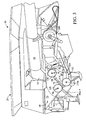
- FIGS 1 and 2 show an agricultural Combine harvester 10 having a supporting structure 12 engaged has means 14 located on the ground, which are from of the supporting structure 12 extend downwards.
- Such one Combine harvester is described in detail in US 6,285,198 the disclosure of which is incorporated by reference into the present Documents is included.
- the invention can be used on any other Types of combine harvesters are used, such as conventional ones Straw walker machines.
- a cutter 16 is used to Harvest crop and feed it to an inclined conveyor 18.
- the crop is one by the feeder 18
- Guide drum 20 supplied.
- the guide drum 20 guides the crop up through an inlet transition section 22 to one axial crop processing unit 24.
- the axial crop processing unit 24 is between the side walls of the combine 10 arranged and supported by them.
- the axial crop processing unit 24 comprises an axial one Rotor housing 26 and one arranged in the rotor housing 26 axial rotor 28.
- the harvested crop passes through the inlet transition section 22 into the rotor housing 26.
- the rotor 28 is with a loading section, a threshing section and equipped with a separating section.
- the rotor housing 26 has each a corresponding loading section, threshing section and Separating portion.
- Both crop processing sections of the rotor 28, the threshing section and the separating section are with good engagement assemblies fitted.
- the threshing section of the rotor housing 26 is equipped with a concave and the separating section with a rust. Grains and chaff released from the mat fall through the concave and the grate.
- the concave and the Rust prevents the passage of crop that is larger than grain or Kaff, in the cleaning system 34th
- the clean grain will then through an elevator 36 for clean grain one Fountain screw conveyor 38 supplied.
- the fountain screw conveyor 38 promotes the grain in a reservoir 40 in the kind of a grain tank.
- the elevator 36 for clean grain and the Fountain screw conveyors 38 include means for moving the clean grain from the grain bottom of the combine in the Storage container 40.
- the grain is conveyed through an unloading conveyor 57 in the form of a screw conveyor from the storage container 40 away.
- the discharge drum 46 conveys the straw to Combine 10 back.
- the operation of the Combine harvester 10 is operated from an operator's cab 48.
- discharge conveyor 56 and 58 in the form of Screw conveyors convey the grain to the side of the storage container 40, where it comes into contact with the discharge conveyor 57, which the clean grain through a vertical unloading tube 61 and a horizontal discharge tube 59 conducts.
- the discharge conveyor 57 includes a vertical section 57a that at least extends partially located within the unloading tube 61 right angle gear 57b, and a horizontal portion 57c within the discharge tube 59.
- the storage container 40 comprises a trough 60, which is a larger one Includes trough area 70 and a smaller trough area 72, which accommodate the horizontal unloading conveyors 56 and 58.
- the Trough 60 is open to a loading case or sump 64.
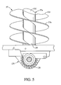
- the vertical portion 57a of the discharge conveyor 57 extends through the vertical tube 61 and into the sump 64 (see FIG. 5). That by the horizontal unloading conveyors 56 and 58 horizontally grain conveyed through the trough 60 is released into the sump 64 and by means of the vertical section 57a through the pipe 61 and by means of the horizontal section 57 c through the discharge tube 59 removed.
- the larger trough area 70 a front sloping wall 76 and a rear sloping wall 78.
- the smaller trough area 72 includes a rear inclined one Wall 82 that curves into rear sloping wall 78 of the larger trough area 70 passes over.
- the swamp 64 includes parallel sidewalls 84 that are substantially parallel extend to each other and vertically and essentially are continuously attached to the inclined walls 78, 82. Just the left side wall 84 of the sump 64 is in the figures visible; the right side wall of the sump 64 has in Essentially the same shape as the left side wall 84.
- the unloading conveyors 56, 58 are driven by pinions 108, 110 driven.
- the discharge conveyor 57 is by a right-angled gear 112 driven by a Input shaft 116a is driven by a pinion 116.
- a drive arrangement for rotating the pinion 108, 110, 116 at normal grain unloading operations are described in more detail in US 4,967 863 A, which is included here by reference.
- the drive assembly can also be of the commercial type Combine harvesters of the applicant's type 9650 STS or 9750 STS available drive arrangement.
- the sump 64 comprises one front oblique wall 118, a rear oblique wall Wall 119 and a casting 120 for the discharge conveyor 57.
- Das Casting 120 is on the inclined walls 118, 119 attached.
- the front oblique wall 118 is on the front inclined wall 76 and on the side walls 84, 86 attached.
- the rear inclined wall 119 is on the rear sloping wall 82 and side walls 84 of the sump 64 attached.
- the side walls 84 of the sump 64, the casting 120 and walls 118, 119 essentially form one enclosed swamp 64 except for those described below Drain holes. If stopper or covers or over Seals screwed into openings in or on the casting 120 are attached, the sump 64 is substantially opposite Sealed trough areas 70, 72.
- the casting 120 includes pivot bearings 122, 124 for rotatably holding a horizontal gear assembly 126 for right angle gear 112.
- Cast part 120 includes also a pivot bearing 130 ( Figure 5) for support and rotatably holding a vertical axis 132 of the unloading conveyor 57.
- a gear 134 with a vertical axis is on axis 132 attached. Rotation of gear 134 also rotates that Unloading conveyor 57.
- the casting 120 includes drain openings 170 that it allow water and / or grain from the lowest areas of the swamp 64 to expire. Close during operation Sealing rings and plates or plugs for drain openings 170. For faster cleaning of sump 64 and trough 60, the walls of the sump 64 can be replaced by a casting which has several grid hole patterns, as in the Patent application US 10/309975 described the disclosure thereof incorporated by reference into this document becomes.
- FIG. 6 shows a drive system 200 for the unloading system for clean grain.
- the grain unloading system driven by a first pulley 238 which by the known drive means 30 is driven as they described, for example, in US Pat. No. 4,967,863.
- On Belt 239 is driven by pulley 238. If the belt 239 is pulled taut, it drives a second Pulley 240 on.
- a clutch assembly 250 causes rotation of the pulley 240.
- the clutch assembly 250 is controlled by control means 254 in the operator's cab 48 controlled.
- a tensioning pulley 256 is used selectably pressed against belt 239 to drive the to achieve second pulley 240.
- the to tension the Belt 239 serving pulley 256 is replaced by a hydraulic cylinder 257 assigned by the Control means 254 is controlled, pressed against the belt 239.
- the pulley 240 has a pinion 302 in Drive connection, which is equipped with a chain 304.
- the chain 304 acts with sprockets 108, 110 to drive the crosswise arranged discharge conveyor 56, 58 and with a pinion 116 for Drive of the discharge conveyor 57 for conveying grain from the Swamp 64 through the vertical tube 61 and the horizontal Discharge tube 59 together.
- Pinion 312 is spring biased to maintain tension in chain 304.
- an additional rotary drive 340 is provided, to rotate the unloading conveyors 56, 57, 58.
- the additional rotary drive 340 includes a third pulley 350, which is firmly attached to the second pulley 240 and the pinion 302 is attached to rotate with them.
- An engine 354 is attached to a lever 356 which at one end 357 swiveling with a fixed bracket on the chassis of the Combine 10 is connected.
- Motor 354 includes one Output shaft 355 on which a drive pulley 360 is appropriate.
- Motor 354 is preferably a 12V DC electric motor, although a pneumatic, hydraulic or other engine also falls under the inventive concept.
- the Motor 354 can operate within a preferred performance range of 150 W to 15 kW and a speed range from 20 to 200 Revolutions per minute.
- motor 354 may 150 watts and a torque of 1.56 Nm and a current consumption of 18.5 A at full load.
- Gear 354a Figure 8 with a gear ratio of approximately 20: 1, motor 354 drives output shaft 355 Load at about 80 revolutions per minute.
- a belt 370 is around and around the third pulley 350 Pulley 360 looped.
- a spring 374 is with one free end portion 375 of the lever 356 and the end 357 of the Lever 356 connected.
- a pneumatic cylinder 378 is between the free end portion 375 of the lever 356 and the end the lever 357 arranged. An extension of cylinder 378 against the biasing force of the spring 374 that the Lever 357 rotates clockwise around end 357 to to tension the belt 370 between the pulleys 350, 360.
- the pulley spends 360 the pulley 350 in rotation when the motor 354 is driven. This way the second Pulley 240 and the pinion 302 set in rotation.
- the motor 354 has a relatively low output and is reduced to the slow output rotation, the turns second pulley 240 slowly. In comparison, turn the unloading conveyors 56, 57 and 58 with grain unloading with 420 Revolutions per minute. Under the action of motor 354 the discharge conveyors rotate during the cleaning operation 56, 57, 58 with about 25 revolutions per minute. One of those slow rotation is advantageous for a cleaning process of the Storage container 40, the horizontal discharge tube 59 and around Unloading conveyor 56, 57, 58 around.
- the cylinder 378 includes a piston rod side 380 and one Piston chamber side 382.
- Pneumatic lines connect the piston rod side 380 with a connection of an electromagnetic Valve 386.
- Figure 6 shows the electromagnetic Valve 386 in the on position. In this position is pressurized air from a supply 388 with the Piston chamber side 382 connected. Air supply 388 may be one external supply via a quick coupling connection 389 or another type of clutch with the piston chamber side 382 is connected. An outlet 390 to the atmosphere is with the Piston rod side 380 of the cylinder 378 connected. In the Compressed air admitted to piston chamber side 382 therefore requires one Extension of a cylinder rod 378a from the cylinder body 378b. This movement tensions the belt 370.
- An electronic control system 406 includes the required Interconnection, 12 V power supply and time control electronics, to operate the system.
- the actuation switch 408 is located preferably on a spiral connection cable 409, that can be plugged into the control system 406.
- the control system 406 comprises a cable 406a, that extends to a raised position near the top of the Storage container 40 extends and ends in a connector 406b.
- Control system 406 also includes a cable 406c that extends to a position extending from the ground near the motor 354 is accessible and ends in a connector 406d.
- the Connection cable 409 can either be plug 406b or 406d to be plugged into the control system 406 by means of the switch 408 control.
- the control system 406 includes a switch line 410 that the Selectable motor 354 supplied with power.
- the control system 406 also includes an electromagnetic actuator line 412 Valve 386.
- the control system 406 is also with Actuating lines 416 provided leading to one or more lead audible alarm devices 420a, 420b.
- the switch 408 and the connecting cable 409 can in various places, such as at ground level and in the amount of the reservoir 40 in the Control system 406 can be plugged in.
- Control system 406 includes a timing circuit or a timing relay switch to delay to be provided while the alarm devices 420a, 420b Make noises.
- Figure 7 shows the mechanical structure of the additional Rotary drive 340 in the drawing.
- the lever 356 is by a Socket or pin 524 rotatable on a holder 524 appropriate.
- the bracket 520 is through fasteners 532 attached to a stationary structure 528 of the combine 10.
- FIG. 8 shows a holder 538, which is attached to the lever 356 is attached, and a bracket 540 attached to a stationary Structure 542 of the combine 10 is attached.
- the cylinder 378 is by pins or bolts (not shown) with the brackets 538, 540 connected.
- the spring 374 is also with the Brackets 538, 540 connected.
- the engine can have a gearbox 354a may be connected to the output shaft 355 if required.
- the system according to the invention provides security advantages.
- the timing circuit delays the start of moving parts of the system while audible before moving parts Alarm devices sound. As soon as it moves, it turns Motor 354 the discharge conveyor 56, 57, 58 with less Speed.
- the system is relatively weak.
- the System switches off when voltage or compressed air drops effectively. It requires both compressed air and voltage to to be turned on. The air pressure must be kept high enough to overcome the spring return force, the 200 N can be.
- the switch 408 is operated and latched manually not a.
Landscapes
- Life Sciences & Earth Sciences (AREA)
- Environmental Sciences (AREA)
- Threshing Machine Elements (AREA)
- Control Of Conveyors (AREA)
Abstract
Description
- Fig. 1
- eine schematische Seitenansicht einer Erntemaschine, in der die vorliegende Erfindung verwirklicht ist,
- Fig. 2
- eine schematische Draufsicht auf die Erntemaschine aus Figur 1,
- Fig. 3
- eine vergrößerte, perspektivische Teilansicht des Vorratsbehälters der Erntemaschine aus Figur 1,
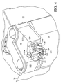
- Fig. 4
- eine von unten betrachtete vergrößerte, perspektivische Teilansicht des in Figur 3 gezeigten Vorratsbehälters,
- Fig. 5
- eine Schnittansicht entlang der Linie 5-5 in Figur 2,
- Fig. 6
- ein Schema des Antriebssystems des Entladeförderers,
- Fig. 7
- eine von vorn aufgenommene, vergrößerte perspektivische Teilansicht eines zusätzlichen Antriebssystems für den Entladeförderer, und
- Fig. 8
- eine von hinten aufgenommene, perspektivische Ansicht des zusätzlichen Antriebssystems aus Figur 7.
Claims (9)
- Erntemaschine, insbesondere Mähdrescher (10), mit einem Vorratsbehälter (40) für geerntetes Erntegut und einem Entladeförderer (56, 57, 58), der mit einer Betriebsgeschwindigkeit betreibbar ist, um Erntegut aus dem Vorratsbehälter (40) hinauszufördern, gekennzeichnet durch einen zusätzlichen Drehantrieb (340), der bei einer Reinigung des Vorratsbehälters (40) antreibbar ist und eingerichtet ist, den Entladeförderer (56, 57, 58) mit einer Geschwindigkeit anzutreiben, die kleiner ist als die Betriebsgeschwindigkeit.
- Erntemaschine nach Anspruch 1, dadurch gekennzeichnet, dass der zusätzliche Drehantrieb (340) einen Motor (354) und eine trennbare Kupplungsanordnung zwischen dem Motor (354) und dem Entladeförderer (56, 57, 58) umfasst.
- Erntemaschine nach Anspruch 2, dadurch gekennzeichnet, dass der Motor (354) ein Elektromotor ist.
- Erntemaschine nach Anspruch 2 oder 3, dadurch gekennzeichnet, dass die Kupplungsanordnung eine Riemenscheibe (360) umfasst, die mit einer rotierbaren Ausgangswelle (355) des zusätzlichen Drehantriebs (340) verbunden ist und über einen Riemen (370) mit einer Riemenscheibe (350) verbunden ist, die mit dem Entladeförderer (56, 57, 58) in Antriebsverbindung steht.
- Erntemaschine nach Anspruch 4, dadurch gekennzeichnet, dass die Kupplungsanordnung eine Spanneinrichtung für den Riemen (370) umfasst.
- Erntemaschine nach Anspruch 5, dadurch gekennzeichnet, dass die Spanneinrichtung einen Zylinder (378) umfasst, der angeordnet ist, zum Ein- und Ausschalten der Kupplungsanordnung die Entfernung zwischen den Riemenscheiben (350, 360) zu verändern.
- Erntemaschine nach einem der Ansprüche 1 bis 6, dadurch gekennzeichnet, dass der zusätzliche Drehantrieb (340) durch einen Schalter (408) ein- und ausschaltbar ist.
- Erntemaschine nach Anspruch 7, dadurch gekennzeichnet, dass der Schalter (408) durch ein langgestrecktes Kabel (409) angeschlossen ist.
- Erntemaschine nach Anspruch 7 oder 8, dadurch gekennzeichnet, dass der zusätzliche Drehantrieb (340) mit einem elektronischen Steuersystem (406) verbunden ist, das eine Zeitsteuerungselektronik und eine hörbare Alarmeinrichtung (420a, 420b) aufweist, und dass die Zeitsteuerungselektronik nach Betätigung des Schalters (408) für eine vorbestimmte Zeitspanne die Alarmeinrichtung (420a, 420b) aktiviert, nach deren Ablauf sie den Drehantrieb (340) aktiviert.
Applications Claiming Priority (2)
| Application Number | Priority Date | Filing Date | Title |
|---|---|---|---|
| US309977 | 2002-12-04 | ||
| US10/309,977 US6743093B1 (en) | 2002-12-04 | 2002-12-04 | Auxiliary drive for combine augers for cleanout |
Publications (2)
| Publication Number | Publication Date |
|---|---|
| EP1425953A1 true EP1425953A1 (de) | 2004-06-09 |
| EP1425953B1 EP1425953B1 (de) | 2006-04-12 |
Family
ID=32312261
Family Applications (1)
| Application Number | Title | Priority Date | Filing Date |
|---|---|---|---|
| EP03027713A Expired - Lifetime EP1425953B1 (de) | 2002-12-04 | 2003-12-02 | Erntemaschine mit Entladeförderer |
Country Status (8)
| Country | Link |
|---|---|
| US (1) | US6743093B1 (de) |
| EP (1) | EP1425953B1 (de) |
| AR (1) | AR042270A1 (de) |
| AU (1) | AU2003257875B2 (de) |
| BR (1) | BR0305342B1 (de) |
| CA (1) | CA2448752C (de) |
| DE (1) | DE50302948D1 (de) |
| DK (1) | DK1425953T3 (de) |
Cited By (3)
| Publication number | Priority date | Publication date | Assignee | Title |
|---|---|---|---|---|
| EP2078451A3 (de) * | 2008-01-10 | 2013-07-10 | CLAAS Selbstfahrende Erntemaschinen GmbH | Mähdrescher |
| CN105340464A (zh) * | 2007-07-31 | 2016-02-24 | 株式会社久保田 | 联合收割机 |
| EP4197311A1 (de) * | 2021-12-16 | 2023-06-21 | CNH Industrial Belgium NV | Erntegutentladerantrieb mit spanner |
Families Citing this family (10)
| Publication number | Priority date | Publication date | Assignee | Title |
|---|---|---|---|---|
| US7367881B2 (en) * | 2006-02-10 | 2008-05-06 | Agco Corporation | High capacity combine grain bin unload system |
| DE102006049779A1 (de) * | 2006-10-21 | 2008-05-21 | Deere & Company, Moline | Überladewagen |
| US9254773B2 (en) * | 2008-05-22 | 2016-02-09 | Cnh Industrial America Llc | Adaptive rate control for feeding grain to a grain unloader conveyor |
| US9156624B2 (en) | 2011-10-11 | 2015-10-13 | Cnh Industrial America Llc | Grain unloading control system |
| CA2852938A1 (en) | 2011-10-21 | 2013-04-25 | Pioneer Hi-Bred International, Inc. | Combine harvester and associated method for gathering grain |
| WO2013188398A1 (en) | 2012-06-13 | 2013-12-19 | Pioneer Hi-Bred International, Inc. | Separably-driven rotor portions and associated method for threshing grain |
| US20150257338A1 (en) * | 2014-03-14 | 2015-09-17 | Deere & Company | Agricultural harvester with bevel gear drive |
| US9510514B2 (en) * | 2015-04-14 | 2016-12-06 | Deere & Company | Lockout closure mechanism for agricultural vehicle |
| JP6838481B2 (ja) * | 2017-04-26 | 2021-03-03 | 井関農機株式会社 | コンバイン |
| US20250151645A1 (en) * | 2023-11-14 | 2025-05-15 | Cnh Industrial America Llc | Grain tank sump for agricultural vehicle |
Citations (2)
| Publication number | Priority date | Publication date | Assignee | Title |
|---|---|---|---|---|
| US3664525A (en) * | 1969-07-25 | 1972-05-23 | Massey Ferguson Gmbh | Rotating grain tank unloader |
| US6285198B1 (en) * | 1995-09-01 | 2001-09-04 | Deere & Company | Grain moisture sensor |
Family Cites Families (21)
| Publication number | Priority date | Publication date | Assignee | Title |
|---|---|---|---|---|
| US3575306A (en) * | 1969-01-24 | 1971-04-20 | Helix Corp | Integrated single-pivot auger box |
| US3561681A (en) * | 1969-05-16 | 1971-02-09 | Letco Inc | Spreader apparatus with auxiliary conveyor means |
| US3872982A (en) * | 1974-06-05 | 1975-03-25 | Sperry Rand Corp | Grain unloading assembly |
| US4037745A (en) | 1976-02-09 | 1977-07-26 | Deere & Company | Combine grain tank unloading mechanism |
| US4138837A (en) | 1976-10-26 | 1979-02-13 | Deere & Company | Variable speed reversible drive for a harvesting apparatus |
| CA1101356A (en) * | 1979-05-29 | 1981-05-19 | Louis Ludwig | Cleaning attachment for grain augers |
| US4430847A (en) | 1982-07-23 | 1984-02-14 | Allis-Chalmers Corporation | Combine feed reverser |
| US4467590A (en) | 1983-12-12 | 1984-08-28 | Sperry Corporation | Drive reversing mechanism |
| US4512139A (en) | 1983-12-12 | 1985-04-23 | Sperry Corporation | Drive reverser actuating mechanism |
| US4470243A (en) | 1983-12-12 | 1984-09-11 | Sperry Corporation | Combine drive control |
| EP0183870B1 (de) | 1984-12-07 | 1989-09-27 | Deere & Company | Entleerungsvorrichtung für den Sammelbehälter einer Erntemaschine |
| US4967863A (en) | 1987-05-15 | 1990-11-06 | Deere & Company | Compact combine drive system |
| US4843803A (en) | 1987-05-15 | 1989-07-04 | Deere & Company | Compact combine drive system |
| US4759185A (en) | 1987-09-18 | 1988-07-26 | Deere & Company | Operator presence switch with service by-pass |
| US4888940A (en) | 1989-01-27 | 1989-12-26 | Deere & Company | Method and apparatus for compacting cotton within a cotton harvester basket |
| US5409344A (en) * | 1994-03-07 | 1995-04-25 | United Farm Tools, Inc. | Portable grain cart auger system |
| GB2289201A (en) | 1994-05-07 | 1995-11-15 | Ford New Holland Nv | Drive reversal for agricultural harvester |
| US5655872A (en) * | 1995-12-20 | 1997-08-12 | Plotkin; David S. | Grain cart with front unload auger |
| JPH11137064A (ja) * | 1997-11-07 | 1999-05-25 | Mitsubishi Agricult Mach Co Ltd | コンバインにおける残留物除去システム |
| JP4331334B2 (ja) * | 1999-07-21 | 2009-09-16 | セイレイ工業株式会社 | 穀粒収穫機における損失粒回収装置 |
| GB2368255A (en) * | 2000-10-23 | 2002-05-01 | Ford New Holland Nv | Grain storage tank for an agricultural harvester |
-
2002
- 2002-12-04 US US10/309,977 patent/US6743093B1/en not_active Expired - Fee Related
-
2003
- 2003-10-24 AU AU2003257875A patent/AU2003257875B2/en not_active Ceased
- 2003-11-07 CA CA002448752A patent/CA2448752C/en not_active Expired - Fee Related
- 2003-11-27 BR BRPI0305342-3B1A patent/BR0305342B1/pt not_active IP Right Cessation
- 2003-12-02 EP EP03027713A patent/EP1425953B1/de not_active Expired - Lifetime
- 2003-12-02 AR ARP030104438A patent/AR042270A1/es active IP Right Grant
- 2003-12-02 DE DE50302948T patent/DE50302948D1/de not_active Expired - Lifetime
- 2003-12-02 DK DK03027713T patent/DK1425953T3/da active
Patent Citations (2)
| Publication number | Priority date | Publication date | Assignee | Title |
|---|---|---|---|---|
| US3664525A (en) * | 1969-07-25 | 1972-05-23 | Massey Ferguson Gmbh | Rotating grain tank unloader |
| US6285198B1 (en) * | 1995-09-01 | 2001-09-04 | Deere & Company | Grain moisture sensor |
Cited By (5)
| Publication number | Priority date | Publication date | Assignee | Title |
|---|---|---|---|---|
| CN105340464A (zh) * | 2007-07-31 | 2016-02-24 | 株式会社久保田 | 联合收割机 |
| CN105340465A (zh) * | 2007-07-31 | 2016-02-24 | 株式会社久保田 | 联合收割机 |
| EP2078451A3 (de) * | 2008-01-10 | 2013-07-10 | CLAAS Selbstfahrende Erntemaschinen GmbH | Mähdrescher |
| EP4197311A1 (de) * | 2021-12-16 | 2023-06-21 | CNH Industrial Belgium NV | Erntegutentladerantrieb mit spanner |
| US12234099B2 (en) | 2021-12-16 | 2025-02-25 | Cnh Industrial America Llc | Crop unloader drive with tensioner |
Also Published As
| Publication number | Publication date |
|---|---|
| US20040110547A1 (en) | 2004-06-10 |
| CA2448752A1 (en) | 2004-06-04 |
| DE50302948D1 (de) | 2006-05-24 |
| AR042270A1 (es) | 2005-06-15 |
| AU2003257875A1 (en) | 2004-06-24 |
| CA2448752C (en) | 2007-06-26 |
| DK1425953T3 (da) | 2006-08-21 |
| EP1425953B1 (de) | 2006-04-12 |
| BR0305342A (pt) | 2004-08-31 |
| US6743093B1 (en) | 2004-06-01 |
| AU2003257875B2 (en) | 2009-05-28 |
| BR0305342B1 (pt) | 2013-08-06 |
Similar Documents
| Publication | Publication Date | Title |
|---|---|---|
| DE60201993T2 (de) | Abschirmmittel für einen elevator einer landwirtschaftlichen erntemaschine | |
| EP1425953B1 (de) | Erntemaschine mit Entladeförderer | |
| EP2022310B1 (de) | Zwischen Breitverteil- und Auswurfkrümmerbetrieb umschaltbare Erntegutresteabgabeanordnung für einen Mähdrescher | |
| EP1074176A1 (de) | Strohhäcksler | |
| EP1425956A2 (de) | Mähdrescher mit Strohhäcksler | |
| DE19918550A1 (de) | Antriebseinrichtung der Förder- und/oder Gutbearbeitungsvorrichtung einer Erntemaschine | |
| DE2336836A1 (de) | Erntemaschine | |
| DE69214072T2 (de) | Steinfangmulde für Mähdrescher | |
| DE2616535A1 (de) | Maehdrescher mit nachdreschvorrichtung | |
| DE1945401A1 (de) | Selbstfahrender Maehdrescher mit Axialdreschmaschine | |
| EP1425952B1 (de) | Reinigungseinrichtung für einen Vorratsbehälter einer Erntemaschine | |
| EP1425954B1 (de) | Reinigungseinrichtung für ein Entladerohr einer Erntemaschine | |
| EP1425951B1 (de) | Erntemaschine mit Entladeförderer | |
| DE69118875T2 (de) | Dreschtrommel mit zweiteiligem Dreschkorb | |
| EP1425950B1 (de) | Vorratsbehälter und Verschlussstopfen | |
| DE69011865T2 (de) | Reinigungsvorrichtung für ein Filterelement. | |
| EP1151660B1 (de) | Erntemaschine, insbesondere selbstfahrender Feldhäcksler | |
| DE2058549A1 (de) | Erntemaschine,insbesondere selbstfahrender Maehdrescher | |
| DE69900324T2 (de) | Verteilmaschine | |
| DE69121085T2 (de) | Schwenkbarer Elevator für Getreide und Spreu | |
| DE4209503C2 (de) | Vorrichtung für selbstfahrende Mähdrescher | |
| EP1530895B1 (de) | Mähdrescher mit Steinfalle | |
| DE102008040125B4 (de) | Mähdrescher mit einem zusätzlichen Förderer zur Strohabförderung | |
| DE102008040119A1 (de) | Mähdrescher mit einem zum Wechsel zwischen Schwadablagebetrieb und Häckselbetrieb in unterschiedlichen Drehrichtungen antreibbaren Trommelförderer | |
| DE69611334T2 (de) | Maschine zum Ernten von runder oder oblonger Früchten wie Gurken |
Legal Events
| Date | Code | Title | Description |
|---|---|---|---|
| PUAI | Public reference made under article 153(3) epc to a published international application that has entered the european phase |
Free format text: ORIGINAL CODE: 0009012 |
|
| AK | Designated contracting states |
Kind code of ref document: A1 Designated state(s): AT BE BG CH CY CZ DE DK EE ES FI FR GB GR HU IE IT LI LU MC NL PT RO SE SI SK TR |
|
| AX | Request for extension of the european patent |
Extension state: AL LT LV MK |
|
| 17P | Request for examination filed |
Effective date: 20041209 |
|
| AKX | Designation fees paid |
Designated state(s): BE DE DK FR GB IT |
|
| GRAP | Despatch of communication of intention to grant a patent |
Free format text: ORIGINAL CODE: EPIDOSNIGR1 |
|
| GRAS | Grant fee paid |
Free format text: ORIGINAL CODE: EPIDOSNIGR3 |
|
| GRAA | (expected) grant |
Free format text: ORIGINAL CODE: 0009210 |
|
| AK | Designated contracting states |
Kind code of ref document: B1 Designated state(s): BE DE DK FR GB IT |
|
| REG | Reference to a national code |
Ref country code: GB Ref legal event code: FG4D Free format text: NOT ENGLISH |
|
| REF | Corresponds to: |
Ref document number: 50302948 Country of ref document: DE Date of ref document: 20060524 Kind code of ref document: P |
|
| GBT | Gb: translation of ep patent filed (gb section 77(6)(a)/1977) |
Effective date: 20060508 |
|
| REG | Reference to a national code |
Ref country code: DK Ref legal event code: T3 |
|
| ET | Fr: translation filed | ||
| PLBE | No opposition filed within time limit |
Free format text: ORIGINAL CODE: 0009261 |
|
| STAA | Information on the status of an ep patent application or granted ep patent |
Free format text: STATUS: NO OPPOSITION FILED WITHIN TIME LIMIT |
|
| 26N | No opposition filed |
Effective date: 20070115 |
|
| PGFP | Annual fee paid to national office [announced via postgrant information from national office to epo] |
Ref country code: GB Payment date: 20131227 Year of fee payment: 11 |
|
| PGFP | Annual fee paid to national office [announced via postgrant information from national office to epo] |
Ref country code: FR Payment date: 20131217 Year of fee payment: 11 Ref country code: IT Payment date: 20131223 Year of fee payment: 11 |
|
| GBPC | Gb: european patent ceased through non-payment of renewal fee |
Effective date: 20141202 |
|
| REG | Reference to a national code |
Ref country code: FR Ref legal event code: ST Effective date: 20150831 |
|
| PG25 | Lapsed in a contracting state [announced via postgrant information from national office to epo] |
Ref country code: GB Free format text: LAPSE BECAUSE OF NON-PAYMENT OF DUE FEES Effective date: 20141202 |
|
| PG25 | Lapsed in a contracting state [announced via postgrant information from national office to epo] |
Ref country code: FR Free format text: LAPSE BECAUSE OF NON-PAYMENT OF DUE FEES Effective date: 20141231 |
|
| PG25 | Lapsed in a contracting state [announced via postgrant information from national office to epo] |
Ref country code: IT Free format text: LAPSE BECAUSE OF NON-PAYMENT OF DUE FEES Effective date: 20141202 |
|
| PGFP | Annual fee paid to national office [announced via postgrant information from national office to epo] |
Ref country code: DK Payment date: 20181227 Year of fee payment: 16 |
|
| PGFP | Annual fee paid to national office [announced via postgrant information from national office to epo] |
Ref country code: BE Payment date: 20181227 Year of fee payment: 16 |
|
| REG | Reference to a national code |
Ref country code: DK Ref legal event code: EBP Effective date: 20191231 |
|
| REG | Reference to a national code |
Ref country code: BE Ref legal event code: MM Effective date: 20191231 |
|
| PG25 | Lapsed in a contracting state [announced via postgrant information from national office to epo] |
Ref country code: BE Free format text: LAPSE BECAUSE OF NON-PAYMENT OF DUE FEES Effective date: 20191231 |
|
| PG25 | Lapsed in a contracting state [announced via postgrant information from national office to epo] |
Ref country code: DK Free format text: LAPSE BECAUSE OF NON-PAYMENT OF DUE FEES Effective date: 20191231 |
|
| REG | Reference to a national code |
Ref country code: DE Ref legal event code: R084 Ref document number: 50302948 Country of ref document: DE |
|
| PGFP | Annual fee paid to national office [announced via postgrant information from national office to epo] |
Ref country code: DE Payment date: 20221121 Year of fee payment: 20 |
|
| REG | Reference to a national code |
Ref country code: DE Ref legal event code: R071 Ref document number: 50302948 Country of ref document: DE |