EP1530895B1 - Mähdrescher mit Steinfalle - Google Patents
Mähdrescher mit Steinfalle Download PDFInfo
- Publication number
- EP1530895B1 EP1530895B1 EP20040105702 EP04105702A EP1530895B1 EP 1530895 B1 EP1530895 B1 EP 1530895B1 EP 20040105702 EP20040105702 EP 20040105702 EP 04105702 A EP04105702 A EP 04105702A EP 1530895 B1 EP1530895 B1 EP 1530895B1
- Authority
- EP
- European Patent Office
- Prior art keywords
- stone trap
- combine harvester
- front wall
- inspection flap
- conveying floor
- Prior art date
- Legal status (The legal status is an assumption and is not a legal conclusion. Google has not performed a legal analysis and makes no representation as to the accuracy of the status listed.)
- Expired - Lifetime
Links
- 239000004575 stone Substances 0.000 title claims description 44
- 238000007689 inspection Methods 0.000 claims description 24
- 238000003306 harvesting Methods 0.000 claims description 13
- 230000007704 transition Effects 0.000 claims description 2
- 238000004140 cleaning Methods 0.000 description 4
- 238000005520 cutting process Methods 0.000 description 3
- 238000002360 preparation method Methods 0.000 description 3
- 239000010902 straw Substances 0.000 description 3
- 239000011435 rock Substances 0.000 description 2
- 241000196324 Embryophyta Species 0.000 description 1
- 240000006829 Ficus sundaica Species 0.000 description 1
- 241001124569 Lycaenidae Species 0.000 description 1
- 241001272996 Polyphylla fullo Species 0.000 description 1
- 238000002485 combustion reaction Methods 0.000 description 1
- 230000005484 gravity Effects 0.000 description 1
- 238000000034 method Methods 0.000 description 1
- 238000003825 pressing Methods 0.000 description 1
- 238000000926 separation method Methods 0.000 description 1
- 230000032258 transport Effects 0.000 description 1
- 238000011144 upstream manufacturing Methods 0.000 description 1
Images


Classifications
-
- A—HUMAN NECESSITIES
- A01—AGRICULTURE; FORESTRY; ANIMAL HUSBANDRY; HUNTING; TRAPPING; FISHING
- A01F—PROCESSING OF HARVESTED PRODUCE; HAY OR STRAW PRESSES; DEVICES FOR STORING AGRICULTURAL OR HORTICULTURAL PRODUCE
- A01F12/00—Parts or details of threshing apparatus
- A01F12/10—Feeders
- A01F12/16—Safety devices
Definitions
- the invention relates to a combine harvester according to the preamble of claim 1.
- combine harvesters When harvested in swaths harvested crop with a header of a combine harvester upstream picker or when cutting the crop near the ground with a cutting unintentionally stones and other hard foreign objects can be recorded and fed to the threshing, which can be seriously damaged.
- combine harvesters are typically provided with a trough-shaped stone trap which is disposed between the threshing device and the feederhouse which conveys crop from the crop receiving device to the threshing device. In the direction of the threshing encouraged subsidized objects hit the Dreschleisten and are thrown in the result in the stone trap.
- the stone trap disposed between the outlet of the feederhouse and the inlet of the threshing means comprises a front wall and a rear wall forming a V-shape in their working position.
- the front wall extends approximately vertically below the outlet of the feederhouse and is hinged on its underside about a horizontally and transversely to the forward axis pivotally mounted on the frame of the combine, so that it can be pivoted by a lever forward in a Steinausschposition
- the rear wall extends approximately from the pivot point of the front wall obliquely backwards and upwards to the inlet of the concave.
- the rear wall is rigidly but releasably connected to the frame of the combine harvester.
- the front wall corresponds to Stone trap of the first embodiment, while the rear wall is pivotally articulated about the pivot axis of the front wall.
- Front and rear wall can be pivoted independently.
- a stone trap which comprises a pivotally hinged trough on side walls of the combine harvester. Below the trough an inspection flap is hinged with its underside also pivotally mounted on side walls of the combine harvester.
- Another stone trap is from the US 4 446 875 A known.
- the front and rear walls form a trough which is connected to a downwardly extending wall which is hinged at its lower end to the frame of the combine harvester.
- the wall and the tub can be swung out altogether.
- the FR 2 141 075 A describes a combine harvester in which a cleaning device is arranged below the stone trap, which is connected to a conveyor bottom arranged below the concave and periodically pierces holes in the bottom of the stone trap for cleaning purposes. To empty the stone trap this is to be removed.
- the stone traps according to EP 0 532 072 A and US 4 446 875 A each have front walls extending between a lower pivot point on the front of the conveyor floor ( EP 0 532 072 A ) or below ( US 4 446 875 A ) and the bottom of the housing of the feederhouse. This provides the opportunity to gain access to the conveyor floor when the front wall is pivoted to the rock ejection position.
- a relatively large lever arm and swiveling path result, so that the filled stone trap must be moved by means of a suitable lever mechanism with a corresponding gear ratio in order to enable the operator to adjust with an appropriate use of force.
- the stone trap and in particular its pivot bearing must be relatively massive because of this lever arm.
- the inspection flap of the EP 0 516 892 A allows easy access to the concave after the stone trap has been completely disassembled, otherwise it blocks the upper half of the gap between the feederhouse and the lower end of the inspection door.
- the object underlying the invention is seen to provide a contrast improved stone trap.
- the conveyor floor inspection flap extends upwardly from the front of the conveyor floor and is pivotally mounted to the frame of the combine on its underside about an axis which is also horizontal and transverse to the forward direction.
- the front wall of the stone trap is to be pivoted forward into the stone ejection position.
- the pivot axis is located directly at the lower end of the front wall, so that no larger torques occur during pivoting and the pivoting path is short. If there is a desire for access to the conveyor floor, the conveyor floor inspection flap is also pivoted forward. In this case, the front wall is pivoted forward, so that a sufficient access to the floor conveyor is possible.
- the conveyor floor inspection flap as long as it is not pivoted forward in order to provide access to the conveyor floor, is locked to the frame of the combine harvester. These can be arranged at their lateral ends arranged locking elements. It thus remains oriented approximately vertically, even if the front wall between stone ejection position and harvesting operation position is moved.
- the rear wall of the stone trap preferably extends from the front of the concave obliquely forward and down to the pivotal mounting of the front wall to the inspection flap. It can be flat or with any curvature.
- the rear wall can be fixed rigidly, for example with screws, but releasably attached to the frame of the combine harvester in order to remove them to provide better access to the conveyor floor or concave can. In another embodiment, it is pivotally hinged to the front wall, on the inspection flap or on the concave.
- FIG. 1 shows a self-propelled combine harvester 10 with a frame 12 which is supported on front, driven and rear steerable wheels 14 on the ground and is moved away from them.
- the wheels 14 are rotated by means not shown drive means in rotation to the combine 10 z. B. to move over a field to be harvested.
- a harvesting device in the form of a cutting unit 16 is connected to harvest crops from the field and feed them up and down by a feeder 18 to a threshing unit.
- the threshing mechanism comprises a transversely arranged threshing drum 20 and a concave 21 associated therewith, to which the harvested crop is first fed.
- the use of straw walkers as Abscheidesch is conceivable. In the following, all directions, such as front, rear, above and below refer to the forward direction of travel V of the combine 10th
- Grain and chaff which are deposited during the threshing, fall on at least one conveyor bottom 30, which feeds them to a preparation tray 33. Grain and chaff, however, emerge from the Axialabscheider 24 fall on one Shaking floor 32, which leads them to the passing on the preparation floor 33.
- the preparation tray 33 forwards the grain and chaff to a cleaner 34 having screens 35 disposed therein, which is associated with a fan 36 to aid in the separation of the chaff from the grain.
- Purified grain is fed by means of a grain auger 38 to an elevator, not shown, which transports it to a grain tank 40.
- a cross auger 42 returns unmanaged ear parts through another elevator, not shown, back into the threshing process.
- the chaff is ejected at the back of the cleaning device 34 onto a vibrating floor 52 which is in a swinging motion.
- the cleaned grain from the grain tank 40 may be discharged through a discharge system with cross augers 44 and a discharge conveyor 46.
- the straw ejected from the axial separator 24 at its rear side is chopped together with the chaff fed by the vibrating floor 52 by a straw chopper 54 and distributed in the field.
- the systems mentioned are driven by means of an internal combustion engine 48.
- the operation of the combine harvester 10 is controlled by an operator from a driver's cab 50.
- the various devices for threshing, conveying, cleaning and separating are located within the frame 12.
- FIG. 2 shows a side view of a marked overall with 56 stone trap and the adjacent areas of the combine 10.
- the inclined conveyor 18 has a housing 58 in which an upper feederhouse roller 60 is rotatably mounted.
- the horizontal and transverse to the direction of rotation axis 62 of the upper inclined conveyor roller 60 simultaneously corresponds to a pivot axis about which the feederhouse 18 is pivotally connected to the frame 12 of the combine 10. This pivoting movement is accomplished by hydraulic cylinders 64 (s. FIG. 1 ).
- the feederhouse 18 has a downwardly facing flap having a surface 66 which cooperates with an upwardly curved surface 68 of the combine 10 connected to the frame 12 to pivot upon pivoting of the feederhouse 18 around the axis 62 to form a seal.
- a conveyor chain 70 with attached drivers 72 which promotes undershoot the picked up by the cutter 16 crop.
- the upper feederhouse roller 60 and / or the lower feederhouse roller is driven.
- the stone trap 56 is located below the transition area between the outlet of the feederhouse 18 and the inlet of the threshing unit. It is used to hold stones that are inadvertently carried in the crop and fall by gravity directly into it or are reflected by the threshing drum 20 into it.
- the stone trap 56 is enclosed by a front wall 74 and a rear wall 76 downwards. In the in the FIG. 2 shown harvesting position form the front wall 74 and the rear wall 76 a V.
- the front wall 74 is articulated on its underside on a pivot bearing 78, so that it is pivotable about an axis extending horizontally and transversely to the forward direction.
- the front wall 74 thus extends in the illustrated harvesting operation position of the pivot bearing 78 obliquely forward and upward and abuts the harvester surface 68.
- the front wall could also abut directly on the housing 58 of the feederhouse 18, particularly on the downwardly curved surface 66, with a flexible seal between the front wall 74 and the feederhouse 18 being used.
- the pivot bearing 78 is located at the top of a conveyor bottom inspection flap 80, which is articulated at its lower end by a further pivot bearing 82 on the frame 12.
- the pivot axis of the pivot bearing 82 also extends horizontally and transversely to the forward direction V.
- the pivot bearing 82 is attached to the top of a front frame part 84 which supports the conveyor bottom 30.
- the frame part 84 is in turn supported in a manner not shown on the frame 12.
- Mounts 86 at both lateral ends of the conveyor bottom inspection flap 80th retain latch members 88 which may be laterally displaced and inserted into suitable openings in the frame 12 for locking the conveyor bottom inspection flap 80 to releasably support the conveyor bottom inspection flap 80 in the illustrated position.
- the rear wall 76 extends from the pivot bearing 78 of the front wall 74 obliquely backwards and upwards to just before the front end of the concave 21. It is rigidly, but releasably secured to the frame 12, for which, for example, screw connections are provided at their lateral ends.
- a lever mechanism 90 is provided, which is composed of a lever 94 with a handle 92 and a strut 96.
- the lever 94 is hinged to a pivot bearing 98 at the front of the frame 12, the pivot axis of which extends horizontally and parallel to the forward direction.
- the handle 92 is located in the harvesting operation position obliquely in front of and below the pivot bearing 98, while the lever 94 rigidly connected to the lever 94 extends from the pivot bearing 98 obliquely upward.
- a further pivot bearing 100 with horizontally and transversely to the forward direction V extending axis of the strut 96, which in turn engages at its other end with a pin 102 in a slot 104 in a bracket 106 at the front of the front wall 74.
- the slot 104 extends parallel to the front wall 74.
- the handle 94 could also be replaced by a power-operated drive so that the operator can empty the stone trap 56 without leaving the cabin 50.
- the operation of the stone trap 56 is as follows: Is the lever 94 in the in FIG. 2 shown harvesting position, the front wall 74 is held in its harvesting operating position. Possibly carried by the feeder 18 stones pass into the stone trap 56 and accumulate there. If the stone trap to be emptied after a certain harvest time, the operator moves the handle 92 in a clockwise direction upwards. The movement is over the lever 94, the pivot bearing 100, the strut 96, the pin 102 on the bracket 106 and the front wall 74 transmitted, which (after the resulting by the slot 104 Leerweg was overcome) pivoted counterclockwise about the pivot bearing 78 down to its stone ejection position becomes. The stones then fall out of the stone trap 56 to the ground.
- the pivot bearing 78 remains in place, since the conveyor bottom inspection flap 80 remains coupled to the frame 12 by the locking elements 88.
- the rear wall 76 also remains stationary.
- the stone trap 56 can thus be emptied without problems, since only the relatively short front wall 74 has to be moved. Subsequently, it can be closed by moving the lever 94 in the reverse direction.
- the operator will release the latch members 88, before or after pivoting the front wall 74 can be made in the stone ejection position.
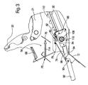
- the conveyor floor inspection flap 80 enters the in FIG. 3 shown position, as soon as the lever 92 has been pivoted from its harvesting operating position in a clockwise direction.
- the elongated hole 104 provides the range of movement required for the movement of the conveyor bottom inspection flap 80 because the console 106 is in the position shown in FIG. 3 shown position further forward than when the conveyor bottom inspection flap 80 is not pivoted.
- the rear wall 76 can be detached and removed, as shown schematically by the removed rear wall 76 'and the arrow 114. After completion of the work, the rear wall 76 is fixed again and the front wall 74 and the conveyor bottom inspection flap 80 are by pressing the lever 94 back into the in FIG. 2 shown position spent. Finally, the locking elements 88 are locked again.
Landscapes
- Harvester Elements (AREA)
- Life Sciences & Earth Sciences (AREA)
- Environmental Sciences (AREA)
Description
- Die Erfindung betrifft einen Mähdrescher nach dem Oberbegriff des Anspruchs 1.
- Bei der Ernte in Schwaden abgelegten Ernteguts mit einem dem Erntevorsatz eines Mähdreschers vorgeordneten Aufnehmer oder beim Schneiden des Ernteguts in der Nähe des Bodens mit einem Schneidwerk können unbeabsichtigt Steine und andere harte Fremdobjekte aufgenommen und der Drescheinrichtung zugeführt werden, die dadurch schwer beschädigt werden kann. Um zu verhindern, dass diese Fremdobjekte in die Drescheinrichtung eintreten, werden Mähdrescher in der Regel mit einer trogförmigen Steinfalle ausgestattet, die zwischen der Drescheinrichtung und dem Schrägförderer angeordnet ist, der Erntegut von der Erntegutaufnahmeeinrichtung zur Drescheinrichtung fördert. In Richtung auf die Drescheinrichtung geförderte Fremdobjekte treffen auf die Dreschleisten und werden im Ergebnis in die Steinfalle geworfen.
- Ein Mähdrescher mit einer Steinfalle ist in der
EP 0 532 072 A beschrieben. Die zwischen dem Auslass des Schrägförderers und dem Einlass der Drescheinrichtung angeordnete Steinfalle umfasst eine Vorderwand und eine Rückwand, die in ihrer Arbeitsposition eine V-Form bilden. - In einer ersten Ausführungsform erstreckt sich die Vorderwand etwa vertikal unterhalb des Auslasses des Schrägförderers und ist an ihrer Unterseite um eine horizontal und quer zur Vorwärtsrichtung verlaufende Achse schwenkbar am Rahmen des Mähdreschers angelenkt, so dass sie durch einen Hebel nach vorn in eine Steinauswurfposition verschwenkt werden kann. Die Rückwand erstreckt sich etwa vom Schwenkpunkt der Vorderwand schräg nach hinten und oben bis zum Einlass des Dreschkorbs. Bei dieser Ausführungsform ist die Rückwand starr, aber lösbar mit dem Rahmen des Mähdreschers verbunden. Wenn die Vorderwand in die Steinauswurfposition verschwenkt wurde und die Rückwand von ihrer Befestigung gelöst ist, bleibt sie durch eine flexible Dichtung mit der Vorderwand eines Förderbodens für ausgedroschene Körner, der sich unterhalb der Dreschtrommel befindet, mit dem Rahmen des Mähdreschers verbunden. Die Rückwand kann somit nach vorn herausgezogen werden, um Zugang zu dem Förderboden und zum vorderen Bereich des Dreschkorbs zu erhalten.
- Bei der zweiten Ausführungsform entspricht die Vorderwand der Steinfalle der ersten Ausführungsform, während die Rückwand um die Schwenkachse der Vorderwand schwenkbar angelenkt ist. Vorder- und Rückwand können unabhängig voneinander verschwenkt werden.
- In der als gattungsbildend angesehenen
EP 0 516 892 A ist eine Steinfalle beschrieben, die einen schwenkbar an Seitenwänden des Mähdreschers angelenkten Trog umfasst. Unterhalb des Trogs ist eine Inspektionsklappe mit ihrer Unterseite ebenfalls schwenkbar an Seitenwänden des Mähdreschers angelenkt. - Eine andere Steinfalle ist aus der
US 4 446 875 A bekannt. Dort bilden Vorder- und Rückwand eine Wanne, die mit einer sich nach unten erstreckenden Wand verbunden ist, die an ihrem unteren Ende am Rahmen des Mähdreschers angelenkt ist. Die Wand und die Wanne können insgesamt herausgeschwenkt werden. - Die
FR 2 141 075 A - Die Steinfallen gemäß
EP 0 532 072 A undUS 4 446 875 A weisen jeweils Vorderwände auf, die sich zwischen einem unteren Schwenkpunkt an der Vorderseite des Förderbodens (EP 0 532 072 A ) oder noch darunter (US 4 446 875 A ) und der Unterseite des Gehäuses des Schrägförderers erstrecken. Dadurch besteht die Möglichkeit, Zugang zum Förderboden zu erhalten, wenn die Vorderwand in die Steinauswurfposition verschwenkt ist. Als nachteilig ist aber anzusehen, dass sich ein relativ großer Hebelarm und Schwenkweg ergibt, so dass die gefüllte Steinfalle über einen geeigneten Hebelmechanismus mit entsprechender Übersetzung bewegt werden muss, um dem Bediener eine Verstellung mit angemessenem Krafteinsatz zu ermöglichen. Außerdem muss die Steinfalle und insbesondere ihre Schwenklagerung wegen dieses Hebelarms relativ massiv dimensioniert werden. Die Inspektionsklappe derEP 0 516 892 A ermöglicht erst einen problemlosen Zugang zum Dreschkorb, nachdem die Steinfalle komplett demontiert wurde, da diese ansonsten die obere Hälfte des Zwischenraums zwischen dem Schrägförderer und dem unteren Ende der Inspektionsklappe blockiert. - Die der Erfindung zu Grunde liegende Aufgabe wird darin gesehen, eine demgegenüber verbesserte Steinfalle bereitzustellen.
- Diese Aufgabe wird erfindungsgemäß durch die Lehre des Patentanspruchs 1 gelöst, wobei in den weiteren Patentansprüchen Merkmale aufgeführt sind, die die Lösung in vorteilhafter Weise weiterentwickeln.
- Es wird vorgeschlagen, die Vorderwand der Steinfalle an der Oberseite der Förderbodeninspektionsklappe anzulenken. Die Förderbodeninspektionsklappe erstreckt sich von der Vorderseite des Förderbodens nach oben und ist an ihrer Unterseite um eine ebenfalls horizontal und quer zur Vorwärtsrichtung verlaufende Achse schwenkbar am Rahmen des Mähdreschers gelagert.
- Zum Ausleeren der Steinfalle ist nur die Vorderwand der Steinfalle nach vorn in die Steinauswurfposition zu verschwenken. Die Schwenkachse befindet sich unmittelbar am unteren Ende der Vorderwand, so dass beim Verschwenken keine größeren Drehmomente auftreten und der Schwenkweg kurz ist. Besteht der Wunsch nach Zugang zum Förderboden, wird auch die Förderbodeninspektionsklappe nach vorn verschwenkt. Dabei wird auch die Vorderwand mit nach vorn verschwenkt, so dass ein hinreichender Zugang zum Förderboden möglich wird.
- Die Förderbodeninspektionsklappe wird, solange sie nicht zwecks Schaffung einer Zugangsmöglichkeit zum Förderboden nach vorn verschwenkt ist, am Rahmen des Mähdreschers arretiert. Dazu können an ihren seitlichen Enden angeordnete Riegelelemente dienen. Sie bleibt somit etwa vertikal orientiert, auch wenn die Vorderwand zwischen Steinauswurfposition und Erntebetriebsposition bewegt wird.
- Die Rückwand der Steinfalle erstreckt sich vorzugsweise von der Vorderseite des Dreschkorbs schräg nach vorn und unten bis zur Schwenklagerung der Vorderwand an der Inspektionsklappe. Sie kann flach oder mit beliebigen Krümmungen ausgeführt sein. Die Rückwand kann starr, beispielsweise mit Schrauben, jedoch lösbar am Rahmen des Mähdreschers befestigt werden, um sie zur Schaffung eines besseren Zugangs zum Förderboden oder zum Dreschkorb herausnehmen zu können. In einer anderen Ausführungsform ist sie schwenkbar an der Vorderwand, an der Inspektionsklappe oder am Dreschkorb angelenkt.
- In den Zeichnungen ist ein nachfolgend näher beschriebenes Ausführungsbeispiel der Erfindung dargestellt. Es zeigt:
- Fig. 1
- einen Mähdrescher in einer schematischen Seitenansicht,
- Fig. 2
- eine seitliche Ansicht der Steinfalle des Mähdreschers aus
Figur 1 in der Erntebetriebsposition, und - Fig. 3
- eine seitliche Ansicht der Steinfalle aus
Figur 2 in der geöffneten Position, in der ein Zugang zum Förderboden möglich ist. - Die
Figur 1 zeigt einen selbstfahrenden Mähdrescher 10 mit einem Rahmen 12, der sich über vordere, angetriebene und hintere lenkbare Räder 14 auf dem Boden abstützt und von diesen fortbewegt wird. Die Räder 14 werden mittels nicht gezeigter Antriebsmittel in Drehung versetzt, um den Mähdrescher 10 z. B. über ein abzuerntendes Feld zu bewegen. An den vorderen Endbereich des Mähdreschers 10 ist eine Erntegutbergungsvorrichtung in Form eines Schneidwerks 16 angeschlossen, um Erntegut von dem Feld zu ernten und es nach oben und hinten durch einen Schrägförderer 18 einem Dreschwerk zuzuführen. Das Dreschwerk umfasst eine quer angeordnete Dreschtrommel 20 und einen dieser zugeordneten Dreschkorb 21, denen das geerntete Gut zuerst zugeführt wird. Eine Abstreifrolle 23 und eine Wendetrommel 22 führen gemeinsam mit einem Zufuhrgehäuse das gedroschene Erntegut von der Dreschtrommel 20 und dem Dreschkorb 21 einem Axialabscheider 24 zu. Auch die Verwendung von Strohschüttlern als Abscheidemittel ist denkbar. Im Folgenden beziehen sich alle Richtungsangaben, wie vorn, hinten, ober- und unterhalb auf die Vorwärtsfahrtrichtung V des Mähdreschers 10. - Getreide und Spreu, die während des Dreschvorgangs abgeschieden werden, fallen auf wenigstens einen Förderboden 30, der sie einem Vorbereitungsboden 33 zuführt. Getreide und Spreu, die hingegen aus dem Axialabscheider 24 austreten, fallen auf einen Schüttelboden 32, der sie zur Weitergabe auf den Vorbereitungsboden 33 führt. Der Vorbereitungsboden 33 gibt das Getreide und die Spreu einer Reinigungseinrichtung 34 mit darin angeordneten Sieben 35 weiter, der ein Gebläse 36 zugeordnet ist, um die Abscheidung der Spreu von dem Getreide zu unterstützen. Gereinigtes Getreide wird mittels einer Körnerschnecke 38 einem nicht gezeigten Elevator zugeführt, der es in einen Korntank 40 befördert. Eine Überkehrschnecke 42 gibt unausgedroschene Ährenteile durch einen weiteren nicht gezeigten Elevator zurück in den Dreschprozess. Die Spreu wird an der Rückseite der Reinigungseinrichtung 34 auf einen sich in einer Schwingbewegung befindlichen Schwingboden 52 ausgeworfen. Das gereinigte Getreide aus dem Korntank 40 kann durch ein Entladesystem mit Querschnecken 44 und einem Entladeförderer 46 entladen werden. Das vom Axialabscheider 24 an seiner Rückseite ausgeworfene Stroh wird gemeinsam mit der durch den Schwingboden 52 zugeführten Spreu durch einen Strohhäcksler 54 gehäckselt und auf dem Feld verteilt.
- Die genannten Systeme werden mittels eines Verbrennungsmotors 48 angetrieben. Der Betrieb des Mähdreschers 10 wird von einer Bedienungsperson aus einer Fahrerkabine 50 heraus kontrolliert. Die verschiedenen Vorrichtungen zum Dreschen, Fördern, Reinigen und Abscheiden befinden sich innerhalb des Rahmens 12.
- Die
Figur 2 zeigt eine seitliche Ansicht einer insgesamt mit 56 gekennzeichneten Steinfalle und der benachbarten Bereiche des Mähdreschers 10. Der Schrägförderer 18 weist ein Gehäuse 58 auf, in dem eine obere Schrägfördererwalze 60 drehbar gelagert ist. Die horizontal und quer zur Fahrtrichtung verlaufende Drehachse 62 der oberen Schrägfördererwalze 60 entspricht gleichzeitig einer Schwenkachse, um die der Schrägförderer 18 am Rahmen 12 des Mähdreschers 10 schwenkbar angelenkt ist. Diese Schwenkbewegung wird durch Hydraulikzylinder 64 bewerkstelligt (s.Figur 1 ). Am hinteren Endbereich des unteren Teils des Gehäuses 58 weist der Schrägförderer 18 eine nach unten weisende Klappe mit einer Oberfläche 66 auf, die an einer mit dem Rahmen 12 verbundenen, nach oben gekrümmten Oberfläche 68 des Mähdreschers 10 zusammenwirkt, um bei einer Verschwenkung des Schrägförderers 18 um die Achse 62 eine Dichtung zu bilden. Um die obere Schrägfördererwalze 60 und eine nicht eingezeichnete untere Schrägfördererwalze läuft eine Förderkette 70 mit daran befestigten Mitnehmern 72 um, die das vom Schneidwerk 16 aufgenommene Erntegut unterschlächtig fördert. Die obere Schrägfördererwalze 60 und/oder die untere Schrägfördererwalze wird angetrieben. - Die Steinfalle 56 befindet sich unterhalb des Übergangsbereichs zwischen dem Auslass des Schrägförderers 18 und dem Einlass des Dreschwerks. Sie dient zur Aufnahme von Steinen, die unbeabsichtigt im Erntegut mitgeführt werden und durch die Schwerkraft direkt in sie fallen oder durch die Dreschtrommel 20 in sie hinein reflektiert werden. Die Steinfalle 56 wird durch eine Vorderwand 74 und eine Rückwand 76 nach unten hin umschlossen. In der in der
Figur 2 dargestellten Erntebetriebsposition bilden die Vorderwand 74 und die Rückwand 76 ein V. - Die Vorderwand 74 ist an ihrer Unterseite an einem Schwenklager 78 angelenkt, so dass sie um eine horizontal und quer zur Vorwärtsrichtung verlaufende Achse verschwenkbar ist. Die Vorderwand 74 erstreckt sich somit in der dargestellten Erntebetriebsposition vom Schwenklager 78 schräg nach vorn und oben und liegt an der mähdrescherfesten Oberfläche 68 an. Bei einer anderen Ausführungsform könnte die Vorderwand auch direkt am Gehäuse 58 des Schrägförderers 18 anliegen, insbesondere an der nach unten gekrümmten Oberfläche 66, wobei eine flexible Dichtung zwischen der Vorderwand 74 und dem Schrägförderer 18 zur Anwendung käme.
- Das Schwenklager 78 befindet sich an der Oberseite einer Förderbodeninspektionsklappe 80, die an ihrem unteren Ende durch eine weitere Schwenklagerung 82 am Rahmen 12 angelenkt ist. Die Schwenkachse der Schwenklagerung 82 erstreckt sich ebenfalls horizontal und quer zur Vorwärtsrichtung V. Die Schwenklagerung 82 ist an der Oberseite eines vorderen Rahmenteils 84 angebracht, das den Förderboden 30 abstützt. Das Rahmenteil 84 ist wiederum in nicht dargestellter Weise am Rahmen 12 abgestützt. Halterungen 86 an beiden seitlichen Enden der Förderbodeninspektionsklappe 80 haltern Riegelelemente 88, die seitlich verschoben und zur Arretierung der Förderbodeninspektionsklappe 80 in geeignete Öffnungen im Rahmen 12 eingeführt werden können, um die Förderbodeninspektionsklappe 80 in der dargestellten Position lösbar zu haltern.
- Die Rückwand 76 erstreckt sich von der Schwenklagerung 78 der Vorderwand 74 schräg nach hinten und oben bis kurz vor das vordere Ende des Dreschkorbs 21. Sie ist starr, aber lösbar am Rahmen 12 befestigt, wozu an ihren seitlichen Enden beispielsweise Schraubverbindungen vorgesehen sind.
- Zur Bewegung der Vorderwand 74 ist eine Hebelmechanik 90 vorgesehen, die sich aus einem Hebel 94 mit einem Handgriff 92 und einer Strebe 96 zusammensetzt. Der Hebel 94 ist an einer Schwenklagerung 98 an der Vorderseite des Rahmens 12 angelenkt, deren Schwenkachse horizontal und parallel zur Vorwärtsrichtung verläuft. Der Handgriff 92 befindet sich in der Erntebetriebsposition schräg vor und unterhalb der Schwenklagerung 98, während sich der mit dem Handgriff 92 starr verbundene Hebel 94 von der Schwenklagerung 98 schräg nach oben erstreckt. Er ist durch eine weitere Schwenklagerung 100 mit horizontal und quer zur Vorwärtsrichtung V verlaufender Achse an der Strebe 96 angelenkt, die an ihren anderen Ende wiederum mit einem Stift 102 in ein Langloch 104 in einer Konsole 106 an der Vorderseite der Vorderwand 74 eingreift. Das Langloch 104 erstreckt sich parallel zur Vorderwand 74. Anzumerken ist, dass der Handgriff 94 auch durch einen fremdkraftbetätigten Antrieb ersetzt werden könnte, damit der Bediener die Steinfalle 56 entleeren kann, ohne die Kabine 50 zu verlassen.
- Die Funktionsweise der erfindungsgemäßen Steinfalle 56 ist folgendermaßen: Befindet sich der Hebel 94 in der in
Figur 2 dargestellten Erntebetriebsposition, wird die Vorderwand 74 in ihrer Erntebetriebsposition gehalten. Eventuell vom Schrägförderer 18 mitgeführte Steine gelangen in die Steinfalle 56 und sammeln sich dort an. Soll die Steinfalle nach Ablauf einer gewissen Erntezeit entleert werden, bewegt der Bediener den Handgriff 92 im Uhrzeigersinn nach oben. Die Bewegung wird über den Hebel 94, die Schwenklagerung 100, die Strebe 96, den Stift 102 auf die Konsole 106 und die Vorderwand 74 übertragen, die (nachdem der durch das Langloch 104 resultierende Leerweg überwunden wurde) im Gegenuhrzeigersinn um die Schwenklagerung 78 nach unten in ihre Steinauswurfposition verschwenkt wird. Die Steine fallen dann aus der Steinfalle 56 heraus auf den Erdboden. Hierbei bleibt die Schwenklagerung 78 an Ort und Stelle, da die Förderbodeninspektionsklappe 80 durch die Riegelelemente 88 mit dem Rahmen 12 gekoppelt bleibt. Auch die Rückwand 76 bleibt stationär. Die Steinfalle 56 kann somit unproblematisch geleert werden, da nur die relativ kurze Vorderwand 74 bewegt werden muss. Anschließend kann sie durch Bewegen des Hebels 94 in umgekehrter Richtung geschlossen werden. - Besteht der Bedarf, Zugang zum vorderen Ende des Förderbodens 30 zu erhalten, beispielsweise um Lagerungen 108 einer Querwelle 110 zum Antrieb der Schneckenförderer 112 des Förderbodens 30 zu warten, oder zum Dreschkorb 21, löst der Bediener die Riegelelemente 88, was vor oder nach dem Verschwenken der Vorderwand 74 in die Steinauswurfposition erfolgen kann. Dadurch gelangt die Förderbodeninspektionsklappe 80 in die in
Figur 3 dargestellte Position, sobald der Hebel 92 aus seiner Erntebetriebsposition im Uhrzeigersinn verschwenkt wurde. Das Langloch 104 stellt den für die Bewegung der Förderbodeninspektionsklappe 80 erforderlichen Bewegungsbereich bereit, da sich die Konsole 106 in der inFigur 3 dargestellten Position weiter vorn befindet, als wenn die Förderbodeninspektionsklappe 80 nicht verschwenkt wird. Die Rückwand 76 kann gelöst und entnommen werden, wie durch die abgenommene Rückwand 76' und den Pfeil 114 schematisch dargestellt ist. Nunmehr besteht ein unproblematischer Zugang zum Förderboden 30 und zur Unter- und Vorderseite des Dreschkorbs 21. Nach Beendigung der Arbeiten wird die Rückwand 76 wieder fixiert und die Vorderwand 74 und die Förderbodeninspektionsklappe 80 werden durch Betätigen des Hebels 94 wieder in die inFigur 2 dargestellte Position verbracht. Schließlich werden die Riegelelemente 88 wieder arretiert. - Im Ergebnis wird eine problemlose Entleerung der Steinfalle 56 und ein guter Zugang zum Förderboden 30 und zum Dreschkorb 21 ermöglicht.
Claims (4)
- Mähdrescher (10) mit einem Schrägförderer (18), einer Dreschtrommel (20) und einem Dreschkorb (21), unter dem sich ein Förderboden (30) zur Förderung ausgedroschener Körner befindet, sowie einer unterhalb des Übergangsbereichs zwischen Schrägförderer (18) und Dreschkorb (21) angeordneten Steinfalle (56), die eine Vorderwand (74) umfasst, welche an ihrem unteren Ende durch ein Schwenklager (78) um eine horizontal und quer zur Vorwärtsrichtung (V) verlaufende Achse in eine Steinauswurfposition verschwenkbar angelenkt ist und sich in einer Erntebetriebsposition von der Achse des Schwenklagers (78) nach oben erstreckt, wobei unterhalb des unteren Endes der Steinfalle (56) eine Förderbodeninspektionsklappe (80) vorhanden ist, die an ihrer Unterseite um eine horizontal und quer zur Vorwärtsrichtung verlaufende Achse an der Vorderseite des Förderbodens (30) schwenkbar am Rahmen (12) des Mähdreschers (10) angelenkt ist, so dass die Förderbodeninspektionsklappe (80) zwecks Schaffung eines Zugangs zum Förderboden (30) und/oder zum Dreschkorb (21) nach vorn verschwenkbar ist, dadurch gekennzeichnet, dass die Vorderwand (74) durch das Schwenklager (78) an der Oberseite der Förderbodeninspektionsklappe (80) schwenkbar angelenkt ist, so dass zwecks Schaffung eines Zugangs zum Förderboden (30) die Förderbodeninspektionsklappe (80) und die Vorderwand (74) gemeinsam um die Achse der Förderbodeninspektionsklappe (80) nach vorn verschwenkbar sind.
- Mähdrescher (10) nach Anspruch 1, dadurch gekennzeichnet, dass die Förderbodeninspektionsklappe (80) am Rahmen (12) des Mähdreschers (10) arretierbar ist.
- Mähdrescher (10) nach Anspruch 1 oder 2, dadurch gekennzeichnet, dass eine Rückwand (76) der Steinfalle (56) sich in der Erntebetriebsposition zwischen der Schwenkachse der Vorderwand (74) und der Vorderseite des Dreschkorbs (21) erstreckt.
- Mähdrescher (10) nach einem der Ansprüche 1 bis 3, dadurch gekennzeichnet, dass die Rückwand (76) der Steinfalle (56) starr, aber lösbar, mit dem Rahmen (12) des Mähdreschers (10) verbindbar ist.
Applications Claiming Priority (2)
| Application Number | Priority Date | Filing Date | Title |
|---|---|---|---|
| DE2003153339 DE10353339A1 (de) | 2003-11-14 | 2003-11-14 | Mähdrescher mit Steinfalle |
| DE10353339 | 2003-11-14 |
Publications (2)
| Publication Number | Publication Date |
|---|---|
| EP1530895A1 EP1530895A1 (de) | 2005-05-18 |
| EP1530895B1 true EP1530895B1 (de) | 2012-09-26 |
Family
ID=34428739
Family Applications (1)
| Application Number | Title | Priority Date | Filing Date |
|---|---|---|---|
| EP20040105702 Expired - Lifetime EP1530895B1 (de) | 2003-11-14 | 2004-11-11 | Mähdrescher mit Steinfalle |
Country Status (2)
| Country | Link |
|---|---|
| EP (1) | EP1530895B1 (de) |
| DE (1) | DE10353339A1 (de) |
Cited By (1)
| Publication number | Priority date | Publication date | Assignee | Title |
|---|---|---|---|---|
| EP4445716A1 (de) * | 2023-04-13 | 2024-10-16 | CLAAS Selbstfahrende Erntemaschinen GmbH | Selbstfahrender mähdrescher |
Families Citing this family (3)
| Publication number | Priority date | Publication date | Assignee | Title |
|---|---|---|---|---|
| DE102009041336A1 (de) | 2009-09-15 | 2011-03-24 | Claas Selbstfahrende Erntemaschinen Gmbh | Steinfangmulde |
| BE1022519B1 (nl) * | 2014-10-20 | 2016-05-19 | Cnh Industrial Belgium Nv | Steenvangergeheel voor een oogstmachine |
| US10405492B2 (en) | 2017-06-19 | 2019-09-10 | Cnh Industrial America Llc | Self-cleaning rock sump for an agricultural harvester and related systems and methods |
Family Cites Families (4)
| Publication number | Priority date | Publication date | Assignee | Title |
|---|---|---|---|---|
| CS149503B1 (en) * | 1971-06-07 | 1973-07-25 | Zbynek Nor | Device for large impurities catching especially for combine-harvesters |
| DE3368487D1 (en) * | 1982-06-15 | 1987-02-05 | Sperry Nv | Stone trap for combine harvesters |
| EP0516892B1 (de) * | 1991-06-04 | 1996-07-24 | New Holland Belgium N.V. | Steinauffangvorrichtung für Mähdrescher |
| GB9118623D0 (en) * | 1991-08-30 | 1991-10-16 | Ford New Holland Inc | Improved stone trap for a combine harvester |
-
2003
- 2003-11-14 DE DE2003153339 patent/DE10353339A1/de not_active Withdrawn
-
2004
- 2004-11-11 EP EP20040105702 patent/EP1530895B1/de not_active Expired - Lifetime
Cited By (1)
| Publication number | Priority date | Publication date | Assignee | Title |
|---|---|---|---|---|
| EP4445716A1 (de) * | 2023-04-13 | 2024-10-16 | CLAAS Selbstfahrende Erntemaschinen GmbH | Selbstfahrender mähdrescher |
Also Published As
| Publication number | Publication date |
|---|---|
| EP1530895A1 (de) | 2005-05-18 |
| DE10353339A1 (de) | 2005-06-02 |
Similar Documents
| Publication | Publication Date | Title |
|---|---|---|
| EP1358789B1 (de) | Mähdrescher mit Strohhäcksler | |
| EP1074176B1 (de) | Strohhäcksler | |
| DE60222881T2 (de) | Schrägförder für landwirtschaftliche erntemaschine | |
| EP1421843B1 (de) | Mähdrescher mit Strohhäcksler | |
| EP1656827B1 (de) | Mähdrescher mit Strohhäcksler | |
| EP1444881B1 (de) | Antriebssystem für einen Erntevorsatz einer Erntemaschine | |
| EP2022310B1 (de) | Zwischen Breitverteil- und Auswurfkrümmerbetrieb umschaltbare Erntegutresteabgabeanordnung für einen Mähdrescher | |
| EP1716736B1 (de) | Mähdrescher | |
| EP2745670B1 (de) | Schrägfördererzusammenbau mit verbesserter Pendelachse | |
| EP2745671B1 (de) | Schrägfördererzusammenbau mit flexiblem Boden | |
| EP1721512A1 (de) | Schneidwerk mit Fördergurtzusammenbauten | |
| EP2250869A1 (de) | Erntegutrestehäcksel und -verteilanordnung für einen Mähdrescher | |
| EP2036425B2 (de) | Dreschkorbanordnung für einen Mähdrescher | |
| EP4209123B1 (de) | Dreschkorb für einen mähdrescher | |
| DE10314081B4 (de) | Austrageinrichtung zum Austragen von Erntegut aus einer Erntemaschine | |
| EP1530895B1 (de) | Mähdrescher mit Steinfalle | |
| EP1579755B1 (de) | Strohleitrechen | |
| EP1595434B1 (de) | Haspelzusammenbau | |
| EP0862849A1 (de) | Gutbearbeitungsvorrichtung | |
| BE1022970B1 (de) | Verstellanordnung zur Verstellung des Arbeitsspaltes eines Korbes einer Dresch- und/oder Trenneinrichtung | |
| DE102006042970B4 (de) | Mähdrescher mit einem dem Strohhäcksler zugeordneten Schutzbügel und einem Strohleitrechen | |
| DE102008040125B4 (de) | Mähdrescher mit einem zusätzlichen Förderer zur Strohabförderung | |
| DE102016125000A1 (de) | Mähdrescher | |
| DE102008040119A1 (de) | Mähdrescher mit einem zum Wechsel zwischen Schwadablagebetrieb und Häckselbetrieb in unterschiedlichen Drehrichtungen antreibbaren Trommelförderer | |
| EP2656723B1 (de) | Erntegutrestehäcksel und -verteilanordnung für einen Mähdrescher mit in eine Schwadablageposition verbringbaren Führungselementen |
Legal Events
| Date | Code | Title | Description |
|---|---|---|---|
| PUAI | Public reference made under article 153(3) epc to a published international application that has entered the european phase |
Free format text: ORIGINAL CODE: 0009012 |
|
| AK | Designated contracting states |
Kind code of ref document: A1 Designated state(s): AT BE BG CH CY CZ DE DK EE ES FI FR GB GR HU IE IS IT LI LU MC NL PL PT RO SE SI SK TR |
|
| AX | Request for extension of the european patent |
Extension state: AL HR LT LV MK YU |
|
| 17P | Request for examination filed |
Effective date: 20051118 |
|
| AKX | Designation fees paid |
Designated state(s): AT BE BG CH CY CZ DE DK EE ES FI FR GB GR HU IE IS IT LI LU MC NL PL PT RO SE SI SK TR |
|
| 17Q | First examination report despatched |
Effective date: 20060928 |
|
| GRAP | Despatch of communication of intention to grant a patent |
Free format text: ORIGINAL CODE: EPIDOSNIGR1 |
|
| GRAS | Grant fee paid |
Free format text: ORIGINAL CODE: EPIDOSNIGR3 |
|
| GRAA | (expected) grant |
Free format text: ORIGINAL CODE: 0009210 |
|
| AK | Designated contracting states |
Kind code of ref document: B1 Designated state(s): AT BE BG CH CY CZ DE DK EE ES FI FR GB GR HU IE IS IT LI LU MC NL PL PT RO SE SI SK TR |
|
| REG | Reference to a national code |
Ref country code: GB Ref legal event code: FG4D Free format text: NOT ENGLISH |
|
| REG | Reference to a national code |
Ref country code: CH Ref legal event code: EP |
|
| REG | Reference to a national code |
Ref country code: AT Ref legal event code: REF Ref document number: 576565 Country of ref document: AT Kind code of ref document: T Effective date: 20121015 |
|
| REG | Reference to a national code |
Ref country code: IE Ref legal event code: FG4D Free format text: LANGUAGE OF EP DOCUMENT: GERMAN |
|
| REG | Reference to a national code |
Ref country code: DE Ref legal event code: R096 Ref document number: 502004013771 Country of ref document: DE Effective date: 20121122 |
|
| PG25 | Lapsed in a contracting state [announced via postgrant information from national office to epo] |
Ref country code: FI Free format text: LAPSE BECAUSE OF FAILURE TO SUBMIT A TRANSLATION OF THE DESCRIPTION OR TO PAY THE FEE WITHIN THE PRESCRIBED TIME-LIMIT Effective date: 20120926 |
|
| REG | Reference to a national code |
Ref country code: NL Ref legal event code: VDEP Effective date: 20120926 |
|
| PG25 | Lapsed in a contracting state [announced via postgrant information from national office to epo] |
Ref country code: SE Free format text: LAPSE BECAUSE OF FAILURE TO SUBMIT A TRANSLATION OF THE DESCRIPTION OR TO PAY THE FEE WITHIN THE PRESCRIBED TIME-LIMIT Effective date: 20120926 Ref country code: SI Free format text: LAPSE BECAUSE OF FAILURE TO SUBMIT A TRANSLATION OF THE DESCRIPTION OR TO PAY THE FEE WITHIN THE PRESCRIBED TIME-LIMIT Effective date: 20120926 Ref country code: GR Free format text: LAPSE BECAUSE OF FAILURE TO SUBMIT A TRANSLATION OF THE DESCRIPTION OR TO PAY THE FEE WITHIN THE PRESCRIBED TIME-LIMIT Effective date: 20121227 |
|
| PG25 | Lapsed in a contracting state [announced via postgrant information from national office to epo] |
Ref country code: ES Free format text: LAPSE BECAUSE OF FAILURE TO SUBMIT A TRANSLATION OF THE DESCRIPTION OR TO PAY THE FEE WITHIN THE PRESCRIBED TIME-LIMIT Effective date: 20130106 Ref country code: NL Free format text: LAPSE BECAUSE OF FAILURE TO SUBMIT A TRANSLATION OF THE DESCRIPTION OR TO PAY THE FEE WITHIN THE PRESCRIBED TIME-LIMIT Effective date: 20120926 Ref country code: RO Free format text: LAPSE BECAUSE OF FAILURE TO SUBMIT A TRANSLATION OF THE DESCRIPTION OR TO PAY THE FEE WITHIN THE PRESCRIBED TIME-LIMIT Effective date: 20120926 Ref country code: CZ Free format text: LAPSE BECAUSE OF FAILURE TO SUBMIT A TRANSLATION OF THE DESCRIPTION OR TO PAY THE FEE WITHIN THE PRESCRIBED TIME-LIMIT Effective date: 20120926 Ref country code: IS Free format text: LAPSE BECAUSE OF FAILURE TO SUBMIT A TRANSLATION OF THE DESCRIPTION OR TO PAY THE FEE WITHIN THE PRESCRIBED TIME-LIMIT Effective date: 20130126 Ref country code: EE Free format text: LAPSE BECAUSE OF FAILURE TO SUBMIT A TRANSLATION OF THE DESCRIPTION OR TO PAY THE FEE WITHIN THE PRESCRIBED TIME-LIMIT Effective date: 20120926 |
|
| PG25 | Lapsed in a contracting state [announced via postgrant information from national office to epo] |
Ref country code: CY Free format text: LAPSE BECAUSE OF FAILURE TO SUBMIT A TRANSLATION OF THE DESCRIPTION OR TO PAY THE FEE WITHIN THE PRESCRIBED TIME-LIMIT Effective date: 20120926 Ref country code: SK Free format text: LAPSE BECAUSE OF FAILURE TO SUBMIT A TRANSLATION OF THE DESCRIPTION OR TO PAY THE FEE WITHIN THE PRESCRIBED TIME-LIMIT Effective date: 20120926 Ref country code: PT Free format text: LAPSE BECAUSE OF FAILURE TO SUBMIT A TRANSLATION OF THE DESCRIPTION OR TO PAY THE FEE WITHIN THE PRESCRIBED TIME-LIMIT Effective date: 20130128 Ref country code: PL Free format text: LAPSE BECAUSE OF FAILURE TO SUBMIT A TRANSLATION OF THE DESCRIPTION OR TO PAY THE FEE WITHIN THE PRESCRIBED TIME-LIMIT Effective date: 20120926 |
|
| REG | Reference to a national code |
Ref country code: CH Ref legal event code: PL |
|
| PG25 | Lapsed in a contracting state [announced via postgrant information from national office to epo] |
Ref country code: CH Free format text: LAPSE BECAUSE OF NON-PAYMENT OF DUE FEES Effective date: 20121130 Ref country code: DK Free format text: LAPSE BECAUSE OF FAILURE TO SUBMIT A TRANSLATION OF THE DESCRIPTION OR TO PAY THE FEE WITHIN THE PRESCRIBED TIME-LIMIT Effective date: 20120926 Ref country code: BG Free format text: LAPSE BECAUSE OF FAILURE TO SUBMIT A TRANSLATION OF THE DESCRIPTION OR TO PAY THE FEE WITHIN THE PRESCRIBED TIME-LIMIT Effective date: 20121226 Ref country code: LI Free format text: LAPSE BECAUSE OF NON-PAYMENT OF DUE FEES Effective date: 20121130 |
|
| PLBE | No opposition filed within time limit |
Free format text: ORIGINAL CODE: 0009261 |
|
| STAA | Information on the status of an ep patent application or granted ep patent |
Free format text: STATUS: NO OPPOSITION FILED WITHIN TIME LIMIT |
|
| REG | Reference to a national code |
Ref country code: IE Ref legal event code: MM4A |
|
| REG | Reference to a national code |
Ref country code: FR Ref legal event code: ST Effective date: 20130731 |
|
| GBPC | Gb: european patent ceased through non-payment of renewal fee |
Effective date: 20121226 |
|
| 26N | No opposition filed |
Effective date: 20130627 |
|
| REG | Reference to a national code |
Ref country code: DE Ref legal event code: R097 Ref document number: 502004013771 Country of ref document: DE Effective date: 20130627 |
|
| PG25 | Lapsed in a contracting state [announced via postgrant information from national office to epo] |
Ref country code: IE Free format text: LAPSE BECAUSE OF NON-PAYMENT OF DUE FEES Effective date: 20121111 |
|
| PG25 | Lapsed in a contracting state [announced via postgrant information from national office to epo] |
Ref country code: FR Free format text: LAPSE BECAUSE OF NON-PAYMENT OF DUE FEES Effective date: 20121130 Ref country code: GB Free format text: LAPSE BECAUSE OF NON-PAYMENT OF DUE FEES Effective date: 20121226 |
|
| REG | Reference to a national code |
Ref country code: AT Ref legal event code: MM01 Ref document number: 576565 Country of ref document: AT Kind code of ref document: T Effective date: 20121130 |
|
| PG25 | Lapsed in a contracting state [announced via postgrant information from national office to epo] |
Ref country code: AT Free format text: LAPSE BECAUSE OF NON-PAYMENT OF DUE FEES Effective date: 20121130 |
|
| PG25 | Lapsed in a contracting state [announced via postgrant information from national office to epo] |
Ref country code: MC Free format text: LAPSE BECAUSE OF NON-PAYMENT OF DUE FEES Effective date: 20121130 Ref country code: TR Free format text: LAPSE BECAUSE OF FAILURE TO SUBMIT A TRANSLATION OF THE DESCRIPTION OR TO PAY THE FEE WITHIN THE PRESCRIBED TIME-LIMIT Effective date: 20120926 |
|
| PG25 | Lapsed in a contracting state [announced via postgrant information from national office to epo] |
Ref country code: LU Free format text: LAPSE BECAUSE OF NON-PAYMENT OF DUE FEES Effective date: 20121111 |
|
| PG25 | Lapsed in a contracting state [announced via postgrant information from national office to epo] |
Ref country code: HU Free format text: LAPSE BECAUSE OF FAILURE TO SUBMIT A TRANSLATION OF THE DESCRIPTION OR TO PAY THE FEE WITHIN THE PRESCRIBED TIME-LIMIT Effective date: 20041111 |
|
| REG | Reference to a national code |
Ref country code: DE Ref legal event code: R084 Ref document number: 502004013771 Country of ref document: DE |
|
| REG | Reference to a national code |
Ref country code: DE Ref legal event code: R084 Ref document number: 502004013771 Country of ref document: DE Effective date: 20141125 |
|
| PGFP | Annual fee paid to national office [announced via postgrant information from national office to epo] |
Ref country code: IT Payment date: 20141124 Year of fee payment: 11 |
|
| PG25 | Lapsed in a contracting state [announced via postgrant information from national office to epo] |
Ref country code: IT Free format text: LAPSE BECAUSE OF NON-PAYMENT OF DUE FEES Effective date: 20151111 |
|
| PGFP | Annual fee paid to national office [announced via postgrant information from national office to epo] |
Ref country code: BE Payment date: 20181127 Year of fee payment: 15 |
|
| REG | Reference to a national code |
Ref country code: BE Ref legal event code: MM Effective date: 20191130 |
|
| PG25 | Lapsed in a contracting state [announced via postgrant information from national office to epo] |
Ref country code: BE Free format text: LAPSE BECAUSE OF NON-PAYMENT OF DUE FEES Effective date: 20191130 |
|
| PGFP | Annual fee paid to national office [announced via postgrant information from national office to epo] |
Ref country code: DE Payment date: 20231019 Year of fee payment: 20 |
|
| REG | Reference to a national code |
Ref country code: DE Ref legal event code: R071 Ref document number: 502004013771 Country of ref document: DE |