EP1530895B1 - Moissoneuse batteuse à recueil de cailloux - Google Patents
Moissoneuse batteuse à recueil de cailloux Download PDFInfo
- Publication number
- EP1530895B1 EP1530895B1 EP20040105702 EP04105702A EP1530895B1 EP 1530895 B1 EP1530895 B1 EP 1530895B1 EP 20040105702 EP20040105702 EP 20040105702 EP 04105702 A EP04105702 A EP 04105702A EP 1530895 B1 EP1530895 B1 EP 1530895B1
- Authority
- EP
- European Patent Office
- Prior art keywords
- stone trap
- combine harvester
- front wall
- inspection flap
- conveying floor
- Prior art date
- Legal status (The legal status is an assumption and is not a legal conclusion. Google has not performed a legal analysis and makes no representation as to the accuracy of the status listed.)
- Active
Links
- 239000004575 stone Substances 0.000 title claims description 44
- 238000007689 inspection Methods 0.000 claims description 24
- 238000003306 harvesting Methods 0.000 claims description 13
- 230000007704 transition Effects 0.000 claims description 2
- 238000004140 cleaning Methods 0.000 description 4
- 238000005520 cutting process Methods 0.000 description 3
- 238000002360 preparation method Methods 0.000 description 3
- 239000010902 straw Substances 0.000 description 3
- 239000011435 rock Substances 0.000 description 2
- 241000196324 Embryophyta Species 0.000 description 1
- 240000006829 Ficus sundaica Species 0.000 description 1
- 241001124569 Lycaenidae Species 0.000 description 1
- 241001272996 Polyphylla fullo Species 0.000 description 1
- 238000002485 combustion reaction Methods 0.000 description 1
- 230000005484 gravity Effects 0.000 description 1
- 238000000034 method Methods 0.000 description 1
- 238000003825 pressing Methods 0.000 description 1
- 238000000926 separation method Methods 0.000 description 1
- 230000032258 transport Effects 0.000 description 1
- 238000011144 upstream manufacturing Methods 0.000 description 1
Images


Classifications
-
- A—HUMAN NECESSITIES
- A01—AGRICULTURE; FORESTRY; ANIMAL HUSBANDRY; HUNTING; TRAPPING; FISHING
- A01F—PROCESSING OF HARVESTED PRODUCE; HAY OR STRAW PRESSES; DEVICES FOR STORING AGRICULTURAL OR HORTICULTURAL PRODUCE
- A01F12/00—Parts or details of threshing apparatus
- A01F12/10—Feeders
- A01F12/16—Safety devices
Definitions
- the invention relates to a combine harvester according to the preamble of claim 1.
- combine harvesters When harvested in swaths harvested crop with a header of a combine harvester upstream picker or when cutting the crop near the ground with a cutting unintentionally stones and other hard foreign objects can be recorded and fed to the threshing, which can be seriously damaged.
- combine harvesters are typically provided with a trough-shaped stone trap which is disposed between the threshing device and the feederhouse which conveys crop from the crop receiving device to the threshing device. In the direction of the threshing encouraged subsidized objects hit the Dreschleisten and are thrown in the result in the stone trap.
- the stone trap disposed between the outlet of the feederhouse and the inlet of the threshing means comprises a front wall and a rear wall forming a V-shape in their working position.
- the front wall extends approximately vertically below the outlet of the feederhouse and is hinged on its underside about a horizontally and transversely to the forward axis pivotally mounted on the frame of the combine, so that it can be pivoted by a lever forward in a Steinausschposition
- the rear wall extends approximately from the pivot point of the front wall obliquely backwards and upwards to the inlet of the concave.
- the rear wall is rigidly but releasably connected to the frame of the combine harvester.
- the front wall corresponds to Stone trap of the first embodiment, while the rear wall is pivotally articulated about the pivot axis of the front wall.
- Front and rear wall can be pivoted independently.
- a stone trap which comprises a pivotally hinged trough on side walls of the combine harvester. Below the trough an inspection flap is hinged with its underside also pivotally mounted on side walls of the combine harvester.
- Another stone trap is from the US 4 446 875 A known.
- the front and rear walls form a trough which is connected to a downwardly extending wall which is hinged at its lower end to the frame of the combine harvester.
- the wall and the tub can be swung out altogether.
- the FR 2 141 075 A describes a combine harvester in which a cleaning device is arranged below the stone trap, which is connected to a conveyor bottom arranged below the concave and periodically pierces holes in the bottom of the stone trap for cleaning purposes. To empty the stone trap this is to be removed.
- the stone traps according to EP 0 532 072 A and US 4 446 875 A each have front walls extending between a lower pivot point on the front of the conveyor floor ( EP 0 532 072 A ) or below ( US 4 446 875 A ) and the bottom of the housing of the feederhouse. This provides the opportunity to gain access to the conveyor floor when the front wall is pivoted to the rock ejection position.
- a relatively large lever arm and swiveling path result, so that the filled stone trap must be moved by means of a suitable lever mechanism with a corresponding gear ratio in order to enable the operator to adjust with an appropriate use of force.
- the stone trap and in particular its pivot bearing must be relatively massive because of this lever arm.
- the inspection flap of the EP 0 516 892 A allows easy access to the concave after the stone trap has been completely disassembled, otherwise it blocks the upper half of the gap between the feederhouse and the lower end of the inspection door.
- the object underlying the invention is seen to provide a contrast improved stone trap.
- the conveyor floor inspection flap extends upwardly from the front of the conveyor floor and is pivotally mounted to the frame of the combine on its underside about an axis which is also horizontal and transverse to the forward direction.
- the front wall of the stone trap is to be pivoted forward into the stone ejection position.
- the pivot axis is located directly at the lower end of the front wall, so that no larger torques occur during pivoting and the pivoting path is short. If there is a desire for access to the conveyor floor, the conveyor floor inspection flap is also pivoted forward. In this case, the front wall is pivoted forward, so that a sufficient access to the floor conveyor is possible.
- the conveyor floor inspection flap as long as it is not pivoted forward in order to provide access to the conveyor floor, is locked to the frame of the combine harvester. These can be arranged at their lateral ends arranged locking elements. It thus remains oriented approximately vertically, even if the front wall between stone ejection position and harvesting operation position is moved.
- the rear wall of the stone trap preferably extends from the front of the concave obliquely forward and down to the pivotal mounting of the front wall to the inspection flap. It can be flat or with any curvature.
- the rear wall can be fixed rigidly, for example with screws, but releasably attached to the frame of the combine harvester in order to remove them to provide better access to the conveyor floor or concave can. In another embodiment, it is pivotally hinged to the front wall, on the inspection flap or on the concave.
- FIG. 1 shows a self-propelled combine harvester 10 with a frame 12 which is supported on front, driven and rear steerable wheels 14 on the ground and is moved away from them.
- the wheels 14 are rotated by means not shown drive means in rotation to the combine 10 z. B. to move over a field to be harvested.
- a harvesting device in the form of a cutting unit 16 is connected to harvest crops from the field and feed them up and down by a feeder 18 to a threshing unit.
- the threshing mechanism comprises a transversely arranged threshing drum 20 and a concave 21 associated therewith, to which the harvested crop is first fed.
- the use of straw walkers as Abscheidesch is conceivable. In the following, all directions, such as front, rear, above and below refer to the forward direction of travel V of the combine 10th
- Grain and chaff which are deposited during the threshing, fall on at least one conveyor bottom 30, which feeds them to a preparation tray 33. Grain and chaff, however, emerge from the Axialabscheider 24 fall on one Shaking floor 32, which leads them to the passing on the preparation floor 33.
- the preparation tray 33 forwards the grain and chaff to a cleaner 34 having screens 35 disposed therein, which is associated with a fan 36 to aid in the separation of the chaff from the grain.
- Purified grain is fed by means of a grain auger 38 to an elevator, not shown, which transports it to a grain tank 40.
- a cross auger 42 returns unmanaged ear parts through another elevator, not shown, back into the threshing process.
- the chaff is ejected at the back of the cleaning device 34 onto a vibrating floor 52 which is in a swinging motion.
- the cleaned grain from the grain tank 40 may be discharged through a discharge system with cross augers 44 and a discharge conveyor 46.
- the straw ejected from the axial separator 24 at its rear side is chopped together with the chaff fed by the vibrating floor 52 by a straw chopper 54 and distributed in the field.
- the systems mentioned are driven by means of an internal combustion engine 48.
- the operation of the combine harvester 10 is controlled by an operator from a driver's cab 50.
- the various devices for threshing, conveying, cleaning and separating are located within the frame 12.
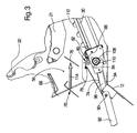
- FIG. 2 shows a side view of a marked overall with 56 stone trap and the adjacent areas of the combine 10.
- the inclined conveyor 18 has a housing 58 in which an upper feederhouse roller 60 is rotatably mounted.
- the horizontal and transverse to the direction of rotation axis 62 of the upper inclined conveyor roller 60 simultaneously corresponds to a pivot axis about which the feederhouse 18 is pivotally connected to the frame 12 of the combine 10. This pivoting movement is accomplished by hydraulic cylinders 64 (s. FIG. 1 ).
- the feederhouse 18 has a downwardly facing flap having a surface 66 which cooperates with an upwardly curved surface 68 of the combine 10 connected to the frame 12 to pivot upon pivoting of the feederhouse 18 around the axis 62 to form a seal.
- a conveyor chain 70 with attached drivers 72 which promotes undershoot the picked up by the cutter 16 crop.
- the upper feederhouse roller 60 and / or the lower feederhouse roller is driven.
- the stone trap 56 is located below the transition area between the outlet of the feederhouse 18 and the inlet of the threshing unit. It is used to hold stones that are inadvertently carried in the crop and fall by gravity directly into it or are reflected by the threshing drum 20 into it.
- the stone trap 56 is enclosed by a front wall 74 and a rear wall 76 downwards. In the in the FIG. 2 shown harvesting position form the front wall 74 and the rear wall 76 a V.
- the front wall 74 is articulated on its underside on a pivot bearing 78, so that it is pivotable about an axis extending horizontally and transversely to the forward direction.
- the front wall 74 thus extends in the illustrated harvesting operation position of the pivot bearing 78 obliquely forward and upward and abuts the harvester surface 68.
- the front wall could also abut directly on the housing 58 of the feederhouse 18, particularly on the downwardly curved surface 66, with a flexible seal between the front wall 74 and the feederhouse 18 being used.
- the pivot bearing 78 is located at the top of a conveyor bottom inspection flap 80, which is articulated at its lower end by a further pivot bearing 82 on the frame 12.
- the pivot axis of the pivot bearing 82 also extends horizontally and transversely to the forward direction V.
- the pivot bearing 82 is attached to the top of a front frame part 84 which supports the conveyor bottom 30.
- the frame part 84 is in turn supported in a manner not shown on the frame 12.
- Mounts 86 at both lateral ends of the conveyor bottom inspection flap 80th retain latch members 88 which may be laterally displaced and inserted into suitable openings in the frame 12 for locking the conveyor bottom inspection flap 80 to releasably support the conveyor bottom inspection flap 80 in the illustrated position.
- the rear wall 76 extends from the pivot bearing 78 of the front wall 74 obliquely backwards and upwards to just before the front end of the concave 21. It is rigidly, but releasably secured to the frame 12, for which, for example, screw connections are provided at their lateral ends.
- a lever mechanism 90 is provided, which is composed of a lever 94 with a handle 92 and a strut 96.
- the lever 94 is hinged to a pivot bearing 98 at the front of the frame 12, the pivot axis of which extends horizontally and parallel to the forward direction.
- the handle 92 is located in the harvesting operation position obliquely in front of and below the pivot bearing 98, while the lever 94 rigidly connected to the lever 94 extends from the pivot bearing 98 obliquely upward.
- a further pivot bearing 100 with horizontally and transversely to the forward direction V extending axis of the strut 96, which in turn engages at its other end with a pin 102 in a slot 104 in a bracket 106 at the front of the front wall 74.
- the slot 104 extends parallel to the front wall 74.
- the handle 94 could also be replaced by a power-operated drive so that the operator can empty the stone trap 56 without leaving the cabin 50.
- the operation of the stone trap 56 is as follows: Is the lever 94 in the in FIG. 2 shown harvesting position, the front wall 74 is held in its harvesting operating position. Possibly carried by the feeder 18 stones pass into the stone trap 56 and accumulate there. If the stone trap to be emptied after a certain harvest time, the operator moves the handle 92 in a clockwise direction upwards. The movement is over the lever 94, the pivot bearing 100, the strut 96, the pin 102 on the bracket 106 and the front wall 74 transmitted, which (after the resulting by the slot 104 Leerweg was overcome) pivoted counterclockwise about the pivot bearing 78 down to its stone ejection position becomes. The stones then fall out of the stone trap 56 to the ground.
- the pivot bearing 78 remains in place, since the conveyor bottom inspection flap 80 remains coupled to the frame 12 by the locking elements 88.
- the rear wall 76 also remains stationary.
- the stone trap 56 can thus be emptied without problems, since only the relatively short front wall 74 has to be moved. Subsequently, it can be closed by moving the lever 94 in the reverse direction.
- the operator will release the latch members 88, before or after pivoting the front wall 74 can be made in the stone ejection position.
- the conveyor floor inspection flap 80 enters the in FIG. 3 shown position, as soon as the lever 92 has been pivoted from its harvesting operating position in a clockwise direction.
- the elongated hole 104 provides the range of movement required for the movement of the conveyor bottom inspection flap 80 because the console 106 is in the position shown in FIG. 3 shown position further forward than when the conveyor bottom inspection flap 80 is not pivoted.
- the rear wall 76 can be detached and removed, as shown schematically by the removed rear wall 76 'and the arrow 114. After completion of the work, the rear wall 76 is fixed again and the front wall 74 and the conveyor bottom inspection flap 80 are by pressing the lever 94 back into the in FIG. 2 shown position spent. Finally, the locking elements 88 are locked again.
Landscapes
- Harvester Elements (AREA)
- Life Sciences & Earth Sciences (AREA)
- Environmental Sciences (AREA)
Claims (4)
- Moissonneuse-batteuse (10), comprenant un transporteur incliné (18), un tambour de battage (20) et un contre-batteur (21) en dessous duquel se situe un fond transporteur (30) pour le transport de grains battus, ainsi qu'un épierreur (56) disposé en dessous de la zone de transition entre le transporteur incliné (18) et le contre-batteur (21), lequel épierreur comporte une paroi avant (74) qui est articulée à son extrémité inférieure au moyen d'un palier de pivotement (78), de manière à pouvoir pivoter, autour d'un axe s'étendant horizontalement et transversalement à la direction d'avance (V), dans une position d'éjection de pierres, et s'étend vers le haut à partir de l'axe du palier de pivotement (78) dans une position de mode de récolte, une trappe d'inspection de fond transporteur (80) étant prévue en dessous de l'extrémité inférieure de l'épierreur (56), laquelle trappe d'inspection est, au niveau de son côté inférieur, articulée sur le cadre (12) de la moissonneuse-batteuse (10) de manière à pouvoir pivoter autour d'un axe s'étendant horizontalement et transversalement à la direction d'avance au niveau du côté avant du fond transporteur (30), de telle sorte que la trappe d'inspection de fond transporteur (80) puisse être pivotée vers l'avant en vue d'obtenir un accès au fond transporteur (30) et/ou au contre-batteur (21), caractérisée en ce que la paroi avant (74) est articulée de manière pivotante, au moyen du palier de pivotement (78), au niveau du côté supérieur de la trappe d'inspection de fond transporteur (80), de telle sorte qu'en vue d'obtenir un accès au fond transporteur (30), la trappe d'inspection de fond transporteur (80) et la paroi avant (74) puissent pivoter conjointement vers l'avant autour de l'axe de la trappe d'inspection de fond transporteur (80).
- Moissonneuse-batteuse (10) selon la revendication 1, caractérisée en ce que la trappe d'inspection de fond transporteur (80) peut être verrouillée sur le cadre (12) de la moissonneuse-batteuse (10).
- Moissonneuse-batteuse (10) selon la revendication 1 ou 2, caractérisée en ce qu'une paroi arrière (76) de l'épierreur (56) s'étend dans la position de mode de récolte entre l'axe de pivotement de la paroi avant (74) et le côté avant du contre-batteur (21).
- Moissonneuse-batteuse (10) selon l'une quelconque des revendications 1 à 3, caractérisée en ce que la paroi arrière (76) de l'épierreur (56) peut être reliée rigidement, mais de manière amovible, au cadre (12) de la moissonneuse-batteuse (10).
Applications Claiming Priority (2)
| Application Number | Priority Date | Filing Date | Title |
|---|---|---|---|
| DE10353339 | 2003-11-14 | ||
| DE2003153339 DE10353339A1 (de) | 2003-11-14 | 2003-11-14 | Mähdrescher mit Steinfalle |
Publications (2)
| Publication Number | Publication Date |
|---|---|
| EP1530895A1 EP1530895A1 (fr) | 2005-05-18 |
| EP1530895B1 true EP1530895B1 (fr) | 2012-09-26 |
Family
ID=34428739
Family Applications (1)
| Application Number | Title | Priority Date | Filing Date |
|---|---|---|---|
| EP20040105702 Active EP1530895B1 (fr) | 2003-11-14 | 2004-11-11 | Moissoneuse batteuse à recueil de cailloux |
Country Status (2)
| Country | Link |
|---|---|
| EP (1) | EP1530895B1 (fr) |
| DE (1) | DE10353339A1 (fr) |
Families Citing this family (3)
| Publication number | Priority date | Publication date | Assignee | Title |
|---|---|---|---|---|
| DE102009041336A1 (de) | 2009-09-15 | 2011-03-24 | Claas Selbstfahrende Erntemaschinen Gmbh | Steinfangmulde |
| BE1022519B1 (nl) * | 2014-10-20 | 2016-05-19 | Cnh Industrial Belgium Nv | Steenvangergeheel voor een oogstmachine |
| US10405492B2 (en) | 2017-06-19 | 2019-09-10 | Cnh Industrial America Llc | Self-cleaning rock sump for an agricultural harvester and related systems and methods |
Family Cites Families (4)
| Publication number | Priority date | Publication date | Assignee | Title |
|---|---|---|---|---|
| CS149503B1 (en) * | 1971-06-07 | 1973-07-25 | Zbynek Nor | Device for large impurities catching especially for combine-harvesters |
| DE3368487D1 (en) * | 1982-06-15 | 1987-02-05 | Sperry Nv | Stone trap for combine harvesters |
| EP0516892B1 (fr) * | 1991-06-04 | 1996-07-24 | New Holland Belgium N.V. | Trappe à pierres pour moissonneuse-batteuse |
| GB9118623D0 (en) * | 1991-08-30 | 1991-10-16 | Ford New Holland Inc | Improved stone trap for a combine harvester |
-
2003
- 2003-11-14 DE DE2003153339 patent/DE10353339A1/de not_active Withdrawn
-
2004
- 2004-11-11 EP EP20040105702 patent/EP1530895B1/fr active Active
Also Published As
| Publication number | Publication date |
|---|---|
| EP1530895A1 (fr) | 2005-05-18 |
| DE10353339A1 (de) | 2005-06-02 |
Similar Documents
| Publication | Publication Date | Title |
|---|---|---|
| EP1358789B1 (fr) | Moissonneuse-batteuse avec hache-paille | |
| EP1074176B1 (fr) | Hache-paille | |
| EP1716736B1 (fr) | Moissonneuse-batteuse | |
| DE60222881T2 (de) | Schrägförder für landwirtschaftliche erntemaschine | |
| EP1656827B1 (fr) | Moissonneuse-batteuse avec hache-paille | |
| EP1444881B1 (fr) | Système d'entraînement pour le système de récolte d'une machine de récolte | |
| EP2022310B1 (fr) | Dispositif de dépôt de résidus de moissons commutable entre fonctionnement de distribution large et collecteur éjecteur pour une moissonneuse-batteuse | |
| EP1421843B1 (fr) | Moissonneuse-batteuse avec hache-paille | |
| EP2745670B1 (fr) | Ensemble convoyeur incliné doté d'un axe oscillant amélioré | |
| EP1721512A1 (fr) | Dispositif de coupe equipé d'un ensemble à bande transporteuse | |
| EP2745671B1 (fr) | Assemblage de convoyeur incliné doté d'un fond flexible | |
| EP2250869A1 (fr) | Agencement de hachage et de répartition de résidus de produits de récolte pour une moissonneuse-batteuse | |
| EP1579755B1 (fr) | Râteau de guidage de paille | |
| DE10314081B4 (de) | Austrageinrichtung zum Austragen von Erntegut aus einer Erntemaschine | |
| EP1595434B1 (fr) | Agencement de rabatteur | |
| EP2036425B2 (fr) | Agencement de panier de battage pour une moissonneuse-batteuse | |
| EP0862849B1 (fr) | Dispositif pour le traitement de récolte | |
| DE102006042970B4 (de) | Mähdrescher mit einem dem Strohhäcksler zugeordneten Schutzbügel und einem Strohleitrechen | |
| EP1530895B1 (fr) | Moissoneuse batteuse à recueil de cailloux | |
| DE102013200235A1 (de) | Schrägfördererzusammenbau für einen Mähdrescher | |
| BE1022970B1 (de) | Verstellanordnung zur Verstellung des Arbeitsspaltes eines Korbes einer Dresch- und/oder Trenneinrichtung | |
| DE102016125000A1 (de) | Mähdrescher | |
| DE102008040125B4 (de) | Mähdrescher mit einem zusätzlichen Förderer zur Strohabförderung | |
| DE102005048052A1 (de) | Erntegutresteverteileinrichtung für einen Mähdrescher | |
| EP2656723B1 (fr) | Agencement de hachage et de répartition de résidus de produits de récolte pour une moissonneuse-batteuse doté d'éléments de guidage pouvant être amenés dans une position d'andainage |
Legal Events
| Date | Code | Title | Description |
|---|---|---|---|
| PUAI | Public reference made under article 153(3) epc to a published international application that has entered the european phase |
Free format text: ORIGINAL CODE: 0009012 |
|
| AK | Designated contracting states |
Kind code of ref document: A1 Designated state(s): AT BE BG CH CY CZ DE DK EE ES FI FR GB GR HU IE IS IT LI LU MC NL PL PT RO SE SI SK TR |
|
| AX | Request for extension of the european patent |
Extension state: AL HR LT LV MK YU |
|
| 17P | Request for examination filed |
Effective date: 20051118 |
|
| AKX | Designation fees paid |
Designated state(s): AT BE BG CH CY CZ DE DK EE ES FI FR GB GR HU IE IS IT LI LU MC NL PL PT RO SE SI SK TR |
|
| 17Q | First examination report despatched |
Effective date: 20060928 |
|
| GRAP | Despatch of communication of intention to grant a patent |
Free format text: ORIGINAL CODE: EPIDOSNIGR1 |
|
| GRAS | Grant fee paid |
Free format text: ORIGINAL CODE: EPIDOSNIGR3 |
|
| GRAA | (expected) grant |
Free format text: ORIGINAL CODE: 0009210 |
|
| AK | Designated contracting states |
Kind code of ref document: B1 Designated state(s): AT BE BG CH CY CZ DE DK EE ES FI FR GB GR HU IE IS IT LI LU MC NL PL PT RO SE SI SK TR |
|
| REG | Reference to a national code |
Ref country code: GB Ref legal event code: FG4D Free format text: NOT ENGLISH |
|
| REG | Reference to a national code |
Ref country code: CH Ref legal event code: EP |
|
| REG | Reference to a national code |
Ref country code: AT Ref legal event code: REF Ref document number: 576565 Country of ref document: AT Kind code of ref document: T Effective date: 20121015 |
|
| REG | Reference to a national code |
Ref country code: IE Ref legal event code: FG4D Free format text: LANGUAGE OF EP DOCUMENT: GERMAN |
|
| REG | Reference to a national code |
Ref country code: DE Ref legal event code: R096 Ref document number: 502004013771 Country of ref document: DE Effective date: 20121122 |
|
| PG25 | Lapsed in a contracting state [announced via postgrant information from national office to epo] |
Ref country code: FI Free format text: LAPSE BECAUSE OF FAILURE TO SUBMIT A TRANSLATION OF THE DESCRIPTION OR TO PAY THE FEE WITHIN THE PRESCRIBED TIME-LIMIT Effective date: 20120926 |
|
| REG | Reference to a national code |
Ref country code: NL Ref legal event code: VDEP Effective date: 20120926 |
|
| PG25 | Lapsed in a contracting state [announced via postgrant information from national office to epo] |
Ref country code: SE Free format text: LAPSE BECAUSE OF FAILURE TO SUBMIT A TRANSLATION OF THE DESCRIPTION OR TO PAY THE FEE WITHIN THE PRESCRIBED TIME-LIMIT Effective date: 20120926 Ref country code: SI Free format text: LAPSE BECAUSE OF FAILURE TO SUBMIT A TRANSLATION OF THE DESCRIPTION OR TO PAY THE FEE WITHIN THE PRESCRIBED TIME-LIMIT Effective date: 20120926 Ref country code: GR Free format text: LAPSE BECAUSE OF FAILURE TO SUBMIT A TRANSLATION OF THE DESCRIPTION OR TO PAY THE FEE WITHIN THE PRESCRIBED TIME-LIMIT Effective date: 20121227 |
|
| PG25 | Lapsed in a contracting state [announced via postgrant information from national office to epo] |
Ref country code: ES Free format text: LAPSE BECAUSE OF FAILURE TO SUBMIT A TRANSLATION OF THE DESCRIPTION OR TO PAY THE FEE WITHIN THE PRESCRIBED TIME-LIMIT Effective date: 20130106 Ref country code: NL Free format text: LAPSE BECAUSE OF FAILURE TO SUBMIT A TRANSLATION OF THE DESCRIPTION OR TO PAY THE FEE WITHIN THE PRESCRIBED TIME-LIMIT Effective date: 20120926 Ref country code: RO Free format text: LAPSE BECAUSE OF FAILURE TO SUBMIT A TRANSLATION OF THE DESCRIPTION OR TO PAY THE FEE WITHIN THE PRESCRIBED TIME-LIMIT Effective date: 20120926 Ref country code: CZ Free format text: LAPSE BECAUSE OF FAILURE TO SUBMIT A TRANSLATION OF THE DESCRIPTION OR TO PAY THE FEE WITHIN THE PRESCRIBED TIME-LIMIT Effective date: 20120926 Ref country code: IS Free format text: LAPSE BECAUSE OF FAILURE TO SUBMIT A TRANSLATION OF THE DESCRIPTION OR TO PAY THE FEE WITHIN THE PRESCRIBED TIME-LIMIT Effective date: 20130126 Ref country code: EE Free format text: LAPSE BECAUSE OF FAILURE TO SUBMIT A TRANSLATION OF THE DESCRIPTION OR TO PAY THE FEE WITHIN THE PRESCRIBED TIME-LIMIT Effective date: 20120926 |
|
| PG25 | Lapsed in a contracting state [announced via postgrant information from national office to epo] |
Ref country code: CY Free format text: LAPSE BECAUSE OF FAILURE TO SUBMIT A TRANSLATION OF THE DESCRIPTION OR TO PAY THE FEE WITHIN THE PRESCRIBED TIME-LIMIT Effective date: 20120926 Ref country code: SK Free format text: LAPSE BECAUSE OF FAILURE TO SUBMIT A TRANSLATION OF THE DESCRIPTION OR TO PAY THE FEE WITHIN THE PRESCRIBED TIME-LIMIT Effective date: 20120926 Ref country code: PT Free format text: LAPSE BECAUSE OF FAILURE TO SUBMIT A TRANSLATION OF THE DESCRIPTION OR TO PAY THE FEE WITHIN THE PRESCRIBED TIME-LIMIT Effective date: 20130128 Ref country code: PL Free format text: LAPSE BECAUSE OF FAILURE TO SUBMIT A TRANSLATION OF THE DESCRIPTION OR TO PAY THE FEE WITHIN THE PRESCRIBED TIME-LIMIT Effective date: 20120926 |
|
| REG | Reference to a national code |
Ref country code: CH Ref legal event code: PL |
|
| PG25 | Lapsed in a contracting state [announced via postgrant information from national office to epo] |
Ref country code: CH Free format text: LAPSE BECAUSE OF NON-PAYMENT OF DUE FEES Effective date: 20121130 Ref country code: DK Free format text: LAPSE BECAUSE OF FAILURE TO SUBMIT A TRANSLATION OF THE DESCRIPTION OR TO PAY THE FEE WITHIN THE PRESCRIBED TIME-LIMIT Effective date: 20120926 Ref country code: BG Free format text: LAPSE BECAUSE OF FAILURE TO SUBMIT A TRANSLATION OF THE DESCRIPTION OR TO PAY THE FEE WITHIN THE PRESCRIBED TIME-LIMIT Effective date: 20121226 Ref country code: LI Free format text: LAPSE BECAUSE OF NON-PAYMENT OF DUE FEES Effective date: 20121130 |
|
| PLBE | No opposition filed within time limit |
Free format text: ORIGINAL CODE: 0009261 |
|
| STAA | Information on the status of an ep patent application or granted ep patent |
Free format text: STATUS: NO OPPOSITION FILED WITHIN TIME LIMIT |
|
| REG | Reference to a national code |
Ref country code: IE Ref legal event code: MM4A |
|
| REG | Reference to a national code |
Ref country code: FR Ref legal event code: ST Effective date: 20130731 |
|
| GBPC | Gb: european patent ceased through non-payment of renewal fee |
Effective date: 20121226 |
|
| 26N | No opposition filed |
Effective date: 20130627 |
|
| REG | Reference to a national code |
Ref country code: DE Ref legal event code: R097 Ref document number: 502004013771 Country of ref document: DE Effective date: 20130627 |
|
| PG25 | Lapsed in a contracting state [announced via postgrant information from national office to epo] |
Ref country code: IE Free format text: LAPSE BECAUSE OF NON-PAYMENT OF DUE FEES Effective date: 20121111 |
|
| PG25 | Lapsed in a contracting state [announced via postgrant information from national office to epo] |
Ref country code: FR Free format text: LAPSE BECAUSE OF NON-PAYMENT OF DUE FEES Effective date: 20121130 Ref country code: GB Free format text: LAPSE BECAUSE OF NON-PAYMENT OF DUE FEES Effective date: 20121226 |
|
| REG | Reference to a national code |
Ref country code: AT Ref legal event code: MM01 Ref document number: 576565 Country of ref document: AT Kind code of ref document: T Effective date: 20121130 |
|
| PG25 | Lapsed in a contracting state [announced via postgrant information from national office to epo] |
Ref country code: AT Free format text: LAPSE BECAUSE OF NON-PAYMENT OF DUE FEES Effective date: 20121130 |
|
| PG25 | Lapsed in a contracting state [announced via postgrant information from national office to epo] |
Ref country code: MC Free format text: LAPSE BECAUSE OF NON-PAYMENT OF DUE FEES Effective date: 20121130 Ref country code: TR Free format text: LAPSE BECAUSE OF FAILURE TO SUBMIT A TRANSLATION OF THE DESCRIPTION OR TO PAY THE FEE WITHIN THE PRESCRIBED TIME-LIMIT Effective date: 20120926 |
|
| PG25 | Lapsed in a contracting state [announced via postgrant information from national office to epo] |
Ref country code: LU Free format text: LAPSE BECAUSE OF NON-PAYMENT OF DUE FEES Effective date: 20121111 |
|
| PG25 | Lapsed in a contracting state [announced via postgrant information from national office to epo] |
Ref country code: HU Free format text: LAPSE BECAUSE OF FAILURE TO SUBMIT A TRANSLATION OF THE DESCRIPTION OR TO PAY THE FEE WITHIN THE PRESCRIBED TIME-LIMIT Effective date: 20041111 |
|
| REG | Reference to a national code |
Ref country code: DE Ref legal event code: R084 Ref document number: 502004013771 Country of ref document: DE |
|
| REG | Reference to a national code |
Ref country code: DE Ref legal event code: R084 Ref document number: 502004013771 Country of ref document: DE Effective date: 20141125 |
|
| PGFP | Annual fee paid to national office [announced via postgrant information from national office to epo] |
Ref country code: IT Payment date: 20141124 Year of fee payment: 11 |
|
| PG25 | Lapsed in a contracting state [announced via postgrant information from national office to epo] |
Ref country code: IT Free format text: LAPSE BECAUSE OF NON-PAYMENT OF DUE FEES Effective date: 20151111 |
|
| PGFP | Annual fee paid to national office [announced via postgrant information from national office to epo] |
Ref country code: BE Payment date: 20181127 Year of fee payment: 15 |
|
| REG | Reference to a national code |
Ref country code: BE Ref legal event code: MM Effective date: 20191130 |
|
| PG25 | Lapsed in a contracting state [announced via postgrant information from national office to epo] |
Ref country code: BE Free format text: LAPSE BECAUSE OF NON-PAYMENT OF DUE FEES Effective date: 20191130 |
|
| PGFP | Annual fee paid to national office [announced via postgrant information from national office to epo] |
Ref country code: DE Payment date: 20231019 Year of fee payment: 20 |