EP1425089B1 - Method for transfer of particulate solid products between zones of different pressure. - Google Patents
Method for transfer of particulate solid products between zones of different pressure. Download PDFInfo
- Publication number
- EP1425089B1 EP1425089B1 EP02762271A EP02762271A EP1425089B1 EP 1425089 B1 EP1425089 B1 EP 1425089B1 EP 02762271 A EP02762271 A EP 02762271A EP 02762271 A EP02762271 A EP 02762271A EP 1425089 B1 EP1425089 B1 EP 1425089B1
- Authority
- EP
- European Patent Office
- Prior art keywords
- pressure
- sluice
- product
- chamber
- piston
- Prior art date
- Legal status (The legal status is an assumption and is not a legal conclusion. Google has not performed a legal analysis and makes no representation as to the accuracy of the status listed.)
- Expired - Lifetime
Links
Images


Classifications
-
- C—CHEMISTRY; METALLURGY
- C10—PETROLEUM, GAS OR COKE INDUSTRIES; TECHNICAL GASES CONTAINING CARBON MONOXIDE; FUELS; LUBRICANTS; PEAT
- C10J—PRODUCTION OF PRODUCER GAS, WATER-GAS, SYNTHESIS GAS FROM SOLID CARBONACEOUS MATERIAL, OR MIXTURES CONTAINING THESE GASES; CARBURETTING AIR OR OTHER GASES
- C10J3/00—Production of combustible gases containing carbon monoxide from solid carbonaceous fuels
- C10J3/46—Gasification of granular or pulverulent flues in suspension
- C10J3/48—Apparatus; Plants
- C10J3/50—Fuel charging devices
- C10J3/503—Fuel charging devices for gasifiers with stationary fluidised bed
-
- B—PERFORMING OPERATIONS; TRANSPORTING
- B65—CONVEYING; PACKING; STORING; HANDLING THIN OR FILAMENTARY MATERIAL
- B65G—TRANSPORT OR STORAGE DEVICES, e.g. CONVEYORS FOR LOADING OR TIPPING, SHOP CONVEYOR SYSTEMS OR PNEUMATIC TUBE CONVEYORS
- B65G53/00—Conveying materials in bulk through troughs, pipes or tubes by floating the materials or by flow of gas, liquid or foam
- B65G53/34—Details
- B65G53/40—Feeding or discharging devices
- B65G53/48—Screws or like rotary conveyors
-
- C—CHEMISTRY; METALLURGY
- C10—PETROLEUM, GAS OR COKE INDUSTRIES; TECHNICAL GASES CONTAINING CARBON MONOXIDE; FUELS; LUBRICANTS; PEAT
- C10J—PRODUCTION OF PRODUCER GAS, WATER-GAS, SYNTHESIS GAS FROM SOLID CARBONACEOUS MATERIAL, OR MIXTURES CONTAINING THESE GASES; CARBURETTING AIR OR OTHER GASES
- C10J2200/00—Details of gasification apparatus
- C10J2200/15—Details of feeding means
- C10J2200/154—Pushing devices, e.g. pistons
-
- C—CHEMISTRY; METALLURGY
- C10—PETROLEUM, GAS OR COKE INDUSTRIES; TECHNICAL GASES CONTAINING CARBON MONOXIDE; FUELS; LUBRICANTS; PEAT
- C10J—PRODUCTION OF PRODUCER GAS, WATER-GAS, SYNTHESIS GAS FROM SOLID CARBONACEOUS MATERIAL, OR MIXTURES CONTAINING THESE GASES; CARBURETTING AIR OR OTHER GASES
- C10J2200/00—Details of gasification apparatus
- C10J2200/15—Details of feeding means
- C10J2200/156—Sluices, e.g. mechanical sluices for preventing escape of gas through the feed inlet
-
- C—CHEMISTRY; METALLURGY
- C10—PETROLEUM, GAS OR COKE INDUSTRIES; TECHNICAL GASES CONTAINING CARBON MONOXIDE; FUELS; LUBRICANTS; PEAT
- C10J—PRODUCTION OF PRODUCER GAS, WATER-GAS, SYNTHESIS GAS FROM SOLID CARBONACEOUS MATERIAL, OR MIXTURES CONTAINING THESE GASES; CARBURETTING AIR OR OTHER GASES
- C10J2200/00—Details of gasification apparatus
- C10J2200/15—Details of feeding means
- C10J2200/158—Screws
Definitions
- the invention relates to a method and apparatus for transfer of particulate products between zones of different pressure.
- the invention is especially suitable for transfer of low density biomass such as straw but not limited to that.
- biomass undergoes pressurized processes, such as steam treatment, hydrolyzation, solvent extraction, pulping, explosion pulping, gasification, drying with superheated steam.
- pressurized processes such as steam treatment, hydrolyzation, solvent extraction, pulping, explosion pulping, gasification, drying with superheated steam.
- the biomass can comprise of dry or wet particles or particles suspended in a liquid.
- SE-C-469536 describes a chamber into which product is conveyed by a piston screw. At the inlet a cylinderknife slides forward and cuts through the product to close the inlet, but its function is to close for product and not to provide a pressure lock. At the outlet there is a pressure lock, but since there is only one, it is not a sluice device as previously defined.
- the apparatus is a plug flow feeder based on the ability of the higly compressed plug of product to reduce escape of gas when the pressure lock is open.
- Rotary locks e.g. US-A-5,114,053, where a rotor, comprising several pockets, rotates continously in a cylindrical housing, demands a product with good flow properties.
- Machine parts have to "cut through” the product, which is problematic especially at the inlet. The product cannot be compressed and forced loading/unloading is not possible.
- a rotor with one sluice chamber turns intermittently, allowing the opening alternately to be connected to the high and the low pressure zones.
- a piston in the sluice chamber secures forced unloading of the sluice chamber and prevents emission from the high pressure zone.
- the product is not force loaded into the sluice chamber, therefore it can not be compressed, and machine parts have to "cut through" the product.
- US-A-5,095,825 describes a method where a rotor has two sluice chambers, which are force unloaded by pistons placed in the sluice chambers.
- the openings of the sluice chambers are placed in one end of the rotor, so that each of them will be connected to one of the two pressure zones when the rotor stops.
- the method seeks to reduce the risk of bridging during loading of the sluice chamber by creating a vacuum with the piston. This means, that the risk of bridging is only partly reduced if the product is penetrable for air. Machine parts would have to "cut through" the product and it is not possible to compress the product by this method.
- SE-C-456645 describes a T-shaped sluice chamber, which forces the product to make a perpendicular movement from horizontal to vertical direction.
- the product is conveyed past the inlet pressure lock and into the sluice chamber by means of a piston or a piston screw, and thereafter the product has to fall by gravity only through the vertikal branch, until it lands on the outlet pressure lock.
- a separate piston secures forced unloading of the sluice chamber.
- the fact that the product during the loading of the sluice chamber has to make a 90° turn by means of gravity only increases the risk of bridging, and makes capacity increasing compression of the product in the sluice chamber impossible.
- SE-C-500516 discloses a device for transfer of a particulate product between two zones of different pressure.
- One problem to be solved in view of the device of SE-C-500516 may be seen as providing an alternative solution to prevent gas leaking between the two pressure zones and also to reduce wear and jamming of the apparatus.
- the present invention provides a method and an apparatus according to appended claims 1 and 17.
- the method invented is based on a sluice system according to which the product is first conveyed through a portioning device, which produces a sequence of uniform product portions divided by uniform particle free spaces, and subsequently the product portions are conveyed individually through a sluice device, which comprises at least one sluice chamber and two pressure locks of which at least one at any time secures a pressure tight barrier between the two pressure zones, and the product portions are force loaded from the first zone into a sluice chamber by means of a piston screw , the axis of which is practically in line with the axis of the sluice chamber, and the product portions are force unloaded from the sluice chamber and into the second pressure zone by means of said piston screw or a piston or by means of gas, steam or liquid supplied at a pressure higher than that of the second pressure zone.
- a piston screw in this context means a screw conveyor to which a reciprocating axial movement can be added independent of the rotation.
- An example of a piston screw is described in SE-C-469536.
- a sluice system in this context means a portioning device combined with a sluice device.
- a sluice device means a sluicechamber combined with pressure locks.
- a sluice chamber in the sense of the invention is a chamber which alternately can be connected to one of two pressure zones, while it at the same time is pressure tight separated from the other pressure zone. The devices which in closed condition secures pressure tight separation will in the following be called pressure locks.
- Force loaded/unloaded means loaded/unloaded by positive product conveying which imply, that other conveying forces than gravity are applied.
- One advantage of the method according to the invention is, that it meets all the requirements for for transfer of particulate, abrasive, low density, non flowing products between zones with different pressures.
- the method according to the invention comprises a portioning device before the sluice device.
- the portioning device produces one or several sequenses of uniform product portions divided by uniform particle free spaces.
- the particle free spaces secures, that no product particles occur in the working space of the pressure locks when they are closing.
- the product portions are conveyed into the sluice device by means of a piston screw.
- the rotation and axial movement of the screw piston can be controlled independently wich makes it possible to provide any degree of compression from light packing to transformation of the product portions into solid plugs.
- the known apparatus is designed to transfer particles of coal and wood with densities from 0,4 - 0,8 compared to 0,05 for shredded straw. This means, that the capacity on straw would drop to app. 10% if the volume of the sluice chamber was unchanged.
- different embodiments of the invention can be selected depending on whether emission from the high pressure zone during transfer of product from the sluice chamber to the high pressure zone is acceptable or not.
- the piston screw which performs the forced loading can also perform the forced unloading of the sluice chamber.
- pressure lock devices can be selected among well known valves such as slid valves, ball valves or piston valves.
- the inner diameter of the valves should at least be of the same size as that of the sluice chamber.
- the pressure of the sluice chamber should be maintained or even increased to accelerate the product to a very high velocity when the pressure lock is opened.
- the diameter of the valve can be much smaller than the diameter of the sluice chamber, because of the high velocity of the product during discharge.
- a ball valve is a good choise because it can be opened completely in a very short time.
- the preferred embodiment of the invention comprises a rotor with two sluice chambers placed practically parallel to the axis of the piston screw, and either perpendicular or parallel to the axis of the rotor and equipped with pistons for forced unloading.
- the sealing system preventing gases vapours or liquid to leak out when product is transferred from the sluice chamber into the high pressure zone have to be resistant to the impact of the chemicals and the temperatures prevailing in the high pressure zone.
- the temperatures can be in the range of 700-1100°C and process gases can contain considerable amounts of tare, wich can condense at the much lower temperature of the sluice chamber.
- process gas can enter into the sluice chamber during unloading, it is known for example from US-A-5,095,825 and DE-A-2426035 A1 to raise the pressure of the sluice chamber before unloading by means of pressurized inert gas.
- the supply of inert gas is however a substantial extra cost, and therefore a special sealing system has been developed to the invention, which practically eliminates leaking of process gas without utilization of pressurized inert gas at all.
- the special sealing system comprises three sealing devices, which will be active at three different places.
- the first sealing device comprises two sealing rings which will be active between the open ends of the sluice chambers and the outlet of the low pressure zone and the inlet of the high pressure zone during loading and unloading.
- This first sealing device is a known type of seal which can be extended to establish tightness during loading respectively unloading and contracted during movement of the rotor in order to avoid friction.
- the second sealing device shall prevent escape of gas, vapour or liquid from the high pressure zone into the part of the sluice chamber behind the piston. Emission can occur when the sealing edges of the piston become worn, which is inevitable especially when silicia is present in the product.
- the second sealing device uses gas, vapour or liquid behind the piston, pressurized to substantially the same pressure as that of the low pressure zone during loading, and pressurized to the same or a higher pressure than that of the high pressure zone during unloading.
- the pressurized gas, vapour or liquid can also be used to move the piston during unloading.
- the third sealing device comprises a vessel housing the rotor and is providing a sealed connection between the two pressure zones. This third sealing device will take care of any emissin from the high pressure zone caused by wear or failures of the two other sealing devices. Any emission to the vessel will be detected and directed to a place where it will do no harm. The detection can release the action nescessary to stop further emission.
- the method of the invention is based on a sluise system comprising a portioning device and a sluice device.
- a sluise system comprising a portioning device and a sluice device.
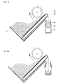
- Example 1 describes a portioning device appropriate for atmospheric conditions and with good buffering capacity for the product to be transferred.
- Fig 1a and 1b are illustrating example 1.
- the feed conveyer 1.2 moves the product under a levelling rotary drum 1.3 creating a product flow with uniform cross section.
- the thickness of the product layer 1.4 can be adjusted by changing the distance between 1.3 and 1.2.
- the product drops into the hopper 1.5 with bottom trap doors 1.6.
- the trap doors 1.6 will open up and the product portion will drop into the belt conveyer 1.7, wich will move the portion into the sluice device (not shown).
- the trap doors 1.6 will be closed and the accumulation of a new product portion will begin.
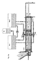
- Example 2 describes a portioning device appropriate for pressurized conditions and with the possibility to serve two sluice devices.
- Fig 2a and 2b illustrates example 2.
- Example 3 describes a sluice device appropriate when a controlled emission is acceptable during transfer of product from the low to the high pressure zone.
- Fig 3a-3i illustrates example 3.
- Example 4 describes an embodiment of the sluice device appropriate when emission during transfer of product from the low to the high pressure zone is unacceptable.
- the flow of the product turns 180° by passing through the sluice device.
- Fig 4a-4e illustrates example 4.
- Example 5 describes like example 4 an embodiment of the sluice device appropriate when emission is unacceptable during transfer of product from the low pressure zone to the high pressure zone.
- the axis of the sluice chamber rotor of example 5 is perpendicular to the axis of the sluice chambers and the piston screw. This means, that the flow of product will maintain the direction imposed by the piston screw by passing through the sluice device.
- the pistons unloading the sluice chambers of example 5 are driven by a pressurized liquid, which at the same time serve as a very effective sealing device against leaking from the high pressure zone into the sluice chamber during forced unloading.
- This sealing method is of special importance when the temperature of the high pressure zone is higher than traditional sealing materials can tolerate as for example the 700-1100°C in a gasifier.
Landscapes
- Chemical & Material Sciences (AREA)
- Engineering & Computer Science (AREA)
- Combustion & Propulsion (AREA)
- Oil, Petroleum & Natural Gas (AREA)
- Organic Chemistry (AREA)
- Mechanical Engineering (AREA)
- Filling Or Emptying Of Bunkers, Hoppers, And Tanks (AREA)
- Feeding, Discharge, Calcimining, Fusing, And Gas-Generation Devices (AREA)
- Screw Conveyors (AREA)
- Physical Or Chemical Processes And Apparatus (AREA)
- Branching, Merging, And Special Transfer Between Conveyors (AREA)
- Transition And Organic Metals Composition Catalysts For Addition Polymerization (AREA)
- Medicinal Preparation (AREA)
- Medical Preparation Storing Or Oral Administration Devices (AREA)
- Control And Other Processes For Unpacking Of Materials (AREA)
Applications Claiming Priority (3)
| Application Number | Priority Date | Filing Date | Title |
|---|---|---|---|
| DKPA200101208 | 2001-08-11 | ||
| DK200101208 | 2001-08-11 | ||
| PCT/DK2002/000507 WO2003013714A1 (en) | 2001-08-11 | 2002-07-22 | Method for transfer of particulate solid products between zones of different pressure. |
Publications (2)
| Publication Number | Publication Date |
|---|---|
| EP1425089A1 EP1425089A1 (en) | 2004-06-09 |
| EP1425089B1 true EP1425089B1 (en) | 2007-03-14 |
Family
ID=8160663
Family Applications (1)
| Application Number | Title | Priority Date | Filing Date |
|---|---|---|---|
| EP02762271A Expired - Lifetime EP1425089B1 (en) | 2001-08-11 | 2002-07-22 | Method for transfer of particulate solid products between zones of different pressure. |
Country Status (20)
| Country | Link |
|---|---|
| US (1) | US7600960B2 (hu) |
| EP (1) | EP1425089B1 (hu) |
| JP (1) | JP4282478B2 (hu) |
| CN (1) | CN1553825B (hu) |
| AT (1) | ATE356659T1 (hu) |
| AU (1) | AU2002328275B2 (hu) |
| BR (1) | BR0211834B1 (hu) |
| CA (1) | CA2456782C (hu) |
| DE (1) | DE60218870T2 (hu) |
| DK (1) | DK1425089T3 (hu) |
| ES (1) | ES2283588T3 (hu) |
| HU (1) | HU228653B1 (hu) |
| MX (1) | MXPA04001284A (hu) |
| NO (1) | NO327681B1 (hu) |
| NZ (1) | NZ531604A (hu) |
| PL (1) | PL205563B1 (hu) |
| PT (1) | PT1425089E (hu) |
| RU (1) | RU2291742C2 (hu) |
| WO (1) | WO2003013714A1 (hu) |
| ZA (1) | ZA200401415B (hu) |
Cited By (1)
| Publication number | Priority date | Publication date | Assignee | Title |
|---|---|---|---|---|
| US8721299B2 (en) | 2009-10-14 | 2014-05-13 | Thermochem Recovery International, Inc. | Piston member, an apparatus comprising the piston member, and methods and use of the piston member and the apparatus |
Families Citing this family (43)
| Publication number | Priority date | Publication date | Assignee | Title |
|---|---|---|---|---|
| NZ601075A (en) | 2005-07-19 | 2014-01-31 | Inbicon As | Method and apparatus for conversion of cellulosic material to ethanol |
| DE102006039622A1 (de) * | 2006-08-24 | 2008-02-28 | Spot Spirit Of Technology Ag | Eintragssystem |
| CN100434153C (zh) * | 2007-02-12 | 2008-11-19 | 西安交通大学 | 一种球形高温高压连续进料气锁系统 |
| US7976259B2 (en) * | 2007-07-16 | 2011-07-12 | Joe David Craig | System for feeding biomass into a pressurized vessel |
| US20090022570A1 (en) * | 2007-07-16 | 2009-01-22 | Joe David Craig | System, method and apparatus for feeding biomass into a pressurized vessel |
| CA2694245C (en) * | 2007-07-25 | 2014-08-26 | Haarslev A/S | A method and a system for the pretreatment of lignocellulosic material |
| US20100014946A1 (en) * | 2007-10-29 | 2010-01-21 | Uop Llc | Catalyst flow control device for transfer of solids between two vessels |
| US20090110517A1 (en) * | 2007-10-29 | 2009-04-30 | Leon Yuan | Catalyst Flow Control Device for Transfer of Solids Between Two Vessels |
| US8057639B2 (en) † | 2008-02-28 | 2011-11-15 | Andritz Inc. | System and method for preextraction of hemicellulose through using a continuous prehydrolysis and steam explosion pretreatment process |
| MY159717A (en) * | 2009-01-13 | 2017-01-31 | Biogasol Aps | Method and apparatus for in-feeding of matter to a process reactor |
| JP5759460B2 (ja) * | 2009-08-27 | 2015-08-05 | インビコン エー/エス | 粒子ポンプの方法およびデバイス |
| WO2011088559A1 (en) * | 2010-01-19 | 2011-07-28 | Hatch Ltd. | Continuous pulverized feedstock to gasifier system and method |
| US9034620B2 (en) | 2010-03-19 | 2015-05-19 | Poet Research, Inc. | System for the treatment of biomass to facilitate the production of ethanol |
| US10533203B2 (en) | 2010-03-19 | 2020-01-14 | Poet Research, Inc. | System for the treatment of biomass |
| US8647012B2 (en) * | 2010-05-05 | 2014-02-11 | Energy Absorption Systems, Inc. | Gate for barrier system and methods for the assembly and use thereof |
| IT1402202B1 (it) * | 2010-09-29 | 2013-08-28 | Chemtex Italia S R L Ora Chemtex Italia S P A | Procedimento migliorato per recuperare zuccheri da un flusso di pretrattamento di biomassa lignocellulosica |
| BR112013010886A2 (pt) | 2010-11-05 | 2016-08-02 | Thermochem Recovery Int Inc | sistema de circulação de sólidos e processo para captura e conversão de sólidos reativos |
| WO2012099967A1 (en) | 2011-01-18 | 2012-07-26 | Poet, Llc | Systems and methods for hydrolysis of biomass |
| US8801859B2 (en) | 2011-05-04 | 2014-08-12 | Renmatix, Inc. | Self-cleaning apparatus and method for thick slurry pressure control |
| CA2840995A1 (en) | 2011-07-07 | 2013-01-10 | Poet Research Incorporated | Systems and methods for acid recycle |
| AU2012315914B2 (en) | 2011-09-27 | 2015-07-09 | Thermochem Recovery International, Inc. | System and method for syngas clean-up |
| SE537195C2 (sv) * | 2012-02-22 | 2015-03-03 | Valmet Oy | Matningsanordning, system och metod för att hantera icketräbaserat växtmaterial |
| WO2014143170A1 (en) * | 2013-03-15 | 2014-09-18 | Koenig Mark E | Isolation gate |
| WO2014168604A1 (en) | 2013-04-08 | 2014-10-16 | Thermochem Recovery International, Inc. | Hydraulic feeder system having compression stage with multi-cylinder hydraulic circuit |
| CN103387852B (zh) * | 2013-07-25 | 2015-02-11 | 中科合成油内蒙古有限公司 | 将含碳固体颗粒从常压环境输送到高压环境中的方法及其装置 |
| US10214751B2 (en) | 2014-10-29 | 2019-02-26 | Cambi Technology As | Method and device for treating biomass and organic waste |
| EP3054051A1 (en) | 2015-02-09 | 2016-08-10 | BETA RENEWABLES S.p.A. | Process to transfer a ligno-cellulosic feedstock |
| EP3054050B1 (en) | 2015-02-09 | 2018-01-24 | BETA RENEWABLES S.p.A. | Pretreatment process of a ligno-cellulosic feedstock |
| EP3054052A1 (en) | 2015-02-09 | 2016-08-10 | BETA RENEWABLES S.p.A. | Improved process to transfer a ligno-cellulosic feedstock |
| EP3300505B1 (de) | 2015-03-05 | 2020-04-29 | Schenck Process Europe GmbH | Vorrichtung und verfahren zum fördern von schüttgut |
| CH711261A1 (de) * | 2015-06-30 | 2016-12-30 | Lehmann Markus | Anlage zur Durchführung eines kontiunierlichen, mehrstufigen Industrieprozesses. |
| ES2940894T3 (es) | 2016-02-16 | 2023-05-12 | Thermochem Recovery Int Inc | Sistema y método de generación de gas producto de energía integrada de dos etapas |
| EP4119637A1 (en) | 2016-03-25 | 2023-01-18 | ThermoChem Recovery International, Inc. | Three-stage energy-integrated product gas generation system and method |
| US10197014B2 (en) | 2016-08-30 | 2019-02-05 | Thermochem Recovery International, Inc. | Feed zone delivery system having carbonaceous feedstock density reduction and gas mixing |
| US10197015B2 (en) * | 2016-08-30 | 2019-02-05 | Thermochem Recovery International, Inc. | Feedstock delivery system having carbonaceous feedstock splitter and gas mixing |
| US10364398B2 (en) | 2016-08-30 | 2019-07-30 | Thermochem Recovery International, Inc. | Method of producing product gas from multiple carbonaceous feedstock streams mixed with a reduced-pressure mixing gas |
| BR112019009111A2 (pt) | 2016-11-04 | 2019-10-15 | Inbicon As | método para a preparação de açúcares fermentáveis a partir de biomassa lignocelulósica |
| IT201700047403A1 (it) * | 2017-05-03 | 2018-11-03 | Ima Spa | Apparato e Metodo per Rivestire Materiale Sfuso |
| US9920926B1 (en) | 2017-07-10 | 2018-03-20 | Thermochem Recovery International, Inc. | Pulse combustion heat exchanger system and method |
| US10099200B1 (en) | 2017-10-24 | 2018-10-16 | Thermochem Recovery International, Inc. | Liquid fuel production system having parallel product gas generation |
| CN110040447B (zh) * | 2019-04-23 | 2020-12-08 | 山东友邦肥业科技有限公司 | 一种下料筒用螺旋回收装置 |
| US11555157B2 (en) | 2020-03-10 | 2023-01-17 | Thermochem Recovery International, Inc. | System and method for liquid fuel production from carbonaceous materials using recycled conditioned syngas |
| US11466223B2 (en) | 2020-09-04 | 2022-10-11 | Thermochem Recovery International, Inc. | Two-stage syngas production with separate char and product gas inputs into the second stage |
Family Cites Families (23)
| Publication number | Priority date | Publication date | Assignee | Title |
|---|---|---|---|---|
| SE218793C1 (hu) * | ||||
| US2732086A (en) * | 1956-01-24 | Apparatus for feeding solids into | ||
| US2765899A (en) * | 1952-04-29 | 1956-10-09 | Wallace & Tiernan Inc | Dry feeder |
| GB1011822A (en) * | 1962-07-16 | 1965-12-01 | Smidth & Co As F L | Improvements relating to methods of feeding materials and to screw conveyors |
| SE399734B (sv) * | 1976-07-05 | 1978-02-27 | Stabilator Ab | Sett och anordning for rortransport av material |
| SE456645B (sv) * | 1983-02-28 | 1988-10-24 | Christopher Sylwan | Foerfarande och trycksluss foer inmatning av icke sjaelvrinnande fast substans i hoegtrycksreaktor |
| FR2626783B1 (fr) * | 1988-02-05 | 1990-07-20 | Renault | Dispositif d'elimination par micro-ondes des particules carbonees contenues dans les gaz d'echappement de moteurs thermiques |
| US5044837A (en) * | 1989-09-14 | 1991-09-03 | Phillips Petroleum Company | Method and apparatus for continuously feeding particulate solid material into a pressurized system without pressure loss |
| FI85186C (fi) | 1989-12-07 | 1996-02-13 | Ahlstroem Oy | Foerfarande och anordning foer inmatning av braensle i ett trycksatt utrymme |
| SE468764B (sv) | 1990-10-04 | 1993-03-15 | Sydkraft Ab | Saett foer inmatning av bulkmaterial i ett utrymme under oevertryck |
| US5087272A (en) * | 1990-10-17 | 1992-02-11 | Nixdorf Richard D | Filter and means for regeneration thereof |
| SE469070B (sv) * | 1991-06-20 | 1993-05-10 | Sydkraft Ab | Apparat foer inmatning av bulkmaterial i ett utrymme under oevertryck |
| SE469536B (sv) * | 1991-12-05 | 1993-07-19 | Vattenfall Energisyst Ab | Saett och anordning foer inmatning av fragmenterat material till behaallare under tryck |
| FI92250C (fi) * | 1992-03-30 | 1994-10-10 | Kone Oy | Menetelmä ja laitteisto aineen syöttämiseksi paineistettuun tilaan |
| DE4217204C2 (de) | 1992-05-23 | 1994-04-14 | Abel Gmbh & Co | Feststoffpumpe |
| DE4236242A1 (de) * | 1992-10-27 | 1994-04-28 | Dornier Gmbh | Verfahren zur Minderung von Russpartikeln in Abgasströmen |
| SE500516C2 (sv) * | 1992-11-13 | 1994-07-11 | Vattenfall Energisyst Ab | Anordning för inmatning av material till en trycksatt behållare, försedd med en strypanordning för intermittent komprimering av det inmatade materialet |
| FI95504C (fi) * | 1994-08-26 | 1996-02-12 | Andritz Patentverwaltung | Menetelmä ja laitteisto paineen tasaamiseksi mäntäsyöttimessä |
| FI98407C (fi) * | 1994-09-22 | 1997-06-10 | Imatran Voima Oy | Menetelmä ja laite kiinteän aineen syöttämiseksi paineistettuun tilaan |
| US5658123A (en) * | 1995-09-15 | 1997-08-19 | Advanced Micro Devices, Inc. | Container-less transfer of semiconductor wafers through a barrier between fabrication areas |
| US6284202B1 (en) * | 1997-10-03 | 2001-09-04 | Cha Corporation | Device for microwave removal of NOx from exhaust gas |
| DE19818935A1 (de) * | 1998-04-28 | 1999-11-04 | Klaus Spies | Verfahren und Vorrichtung zum Einbringen von festen schüttgutartigen bis flüssig-teigigen Stoffen in Prozeßabläufe, vor allem Fördersysteme mit höherem Druckniveau |
| JP2005503893A (ja) * | 2001-10-04 | 2005-02-10 | ザ ジョンズ ホプキンズ ユニバーシティ | 空気感染病原体の中和 |
-
2002
- 2002-07-22 MX MXPA04001284A patent/MXPA04001284A/es active IP Right Grant
- 2002-07-22 PL PL368194A patent/PL205563B1/pl unknown
- 2002-07-22 CA CA2456782A patent/CA2456782C/en not_active Expired - Fee Related
- 2002-07-22 PT PT02762271T patent/PT1425089E/pt unknown
- 2002-07-22 JP JP2003518709A patent/JP4282478B2/ja not_active Expired - Fee Related
- 2002-07-22 RU RU2004107132/15A patent/RU2291742C2/ru not_active IP Right Cessation
- 2002-07-22 EP EP02762271A patent/EP1425089B1/en not_active Expired - Lifetime
- 2002-07-22 HU HU0401027A patent/HU228653B1/hu not_active IP Right Cessation
- 2002-07-22 US US10/486,102 patent/US7600960B2/en not_active Expired - Fee Related
- 2002-07-22 BR BRPI0211834-3A patent/BR0211834B1/pt not_active IP Right Cessation
- 2002-07-22 NZ NZ531604A patent/NZ531604A/en not_active IP Right Cessation
- 2002-07-22 AT AT02762271T patent/ATE356659T1/de active
- 2002-07-22 WO PCT/DK2002/000507 patent/WO2003013714A1/en active IP Right Grant
- 2002-07-22 DE DE60218870T patent/DE60218870T2/de not_active Expired - Lifetime
- 2002-07-22 ES ES02762271T patent/ES2283588T3/es not_active Expired - Lifetime
- 2002-07-22 AU AU2002328275A patent/AU2002328275B2/en not_active Ceased
- 2002-07-22 CN CN028175999A patent/CN1553825B/zh not_active Expired - Fee Related
- 2002-07-22 DK DK02762271T patent/DK1425089T3/da active
-
2004
- 2004-02-02 NO NO20040470A patent/NO327681B1/no not_active IP Right Cessation
- 2004-02-20 ZA ZA2004/01415A patent/ZA200401415B/en unknown
Cited By (1)
| Publication number | Priority date | Publication date | Assignee | Title |
|---|---|---|---|---|
| US8721299B2 (en) | 2009-10-14 | 2014-05-13 | Thermochem Recovery International, Inc. | Piston member, an apparatus comprising the piston member, and methods and use of the piston member and the apparatus |
Also Published As
| Publication number | Publication date |
|---|---|
| HUP0401027A2 (hu) | 2004-09-28 |
| MXPA04001284A (es) | 2005-06-06 |
| ATE356659T1 (de) | 2007-04-15 |
| PL368194A1 (en) | 2005-03-21 |
| ZA200401415B (en) | 2005-01-26 |
| US7600960B2 (en) | 2009-10-13 |
| JP2004536754A (ja) | 2004-12-09 |
| CN1553825B (zh) | 2010-06-16 |
| DK1425089T3 (da) | 2007-11-26 |
| BR0211834A (pt) | 2004-09-08 |
| HUP0401027A3 (en) | 2009-05-28 |
| ES2283588T3 (es) | 2007-11-01 |
| PL205563B1 (pl) | 2010-05-31 |
| CA2456782A1 (en) | 2003-02-20 |
| NO327681B1 (no) | 2009-09-07 |
| NO20040470L (no) | 2004-03-31 |
| US20040184900A1 (en) | 2004-09-23 |
| EP1425089A1 (en) | 2004-06-09 |
| BR0211834B1 (pt) | 2012-09-04 |
| RU2291742C2 (ru) | 2007-01-20 |
| DE60218870T2 (de) | 2007-11-29 |
| NZ531604A (en) | 2005-11-25 |
| RU2004107132A (ru) | 2005-05-10 |
| JP4282478B2 (ja) | 2009-06-24 |
| CA2456782C (en) | 2011-10-25 |
| AU2002328275B2 (en) | 2008-03-06 |
| DE60218870D1 (de) | 2007-04-26 |
| CN1553825A (zh) | 2004-12-08 |
| WO2003013714A1 (en) | 2003-02-20 |
| HU228653B1 (en) | 2013-05-28 |
| PT1425089E (pt) | 2007-06-05 |
Similar Documents
| Publication | Publication Date | Title |
|---|---|---|
| EP1425089B1 (en) | Method for transfer of particulate solid products between zones of different pressure. | |
| AU2002328275A1 (en) | Method for transfer of particulate solid products between zones of different pressure. | |
| US4881862A (en) | Screw seal | |
| US5558473A (en) | Labyrinth seal coal injector | |
| EP0431639B1 (en) | Method and apparatus for feeding fuel into a pressurized space | |
| US4140228A (en) | Dry piston coal feeder | |
| US5044837A (en) | Method and apparatus for continuously feeding particulate solid material into a pressurized system without pressure loss | |
| US20180022554A1 (en) | Device and method for conveying bulk material into a pressure chamber | |
| EP0782474B1 (en) | Method and apparatus for feeding solid material into a pressurized space | |
| US4148405A (en) | Solid feeder and method | |
| CN107406779B (zh) | 用于输送散料的装置和方法 | |
| CA1062645A (en) | Pressurized conveyor | |
| CN111606053A (zh) | 旋转式粉体加压输送装置 | |
| AU747579B2 (en) | Method and device for feeding granular solid substances into pressure systems or pressure reactors | |
| GB2114526A (en) | Method and apparatus for conveying abrasive solids | |
| AU7667694A (en) | Material transfer device with multi-chamber rotor | |
| EP0784586A1 (en) | Transferring bulk goods between conveyors | |
| AU2005291860B2 (en) | Pump apparatus | |
| FI88539C (fi) | Foerfarande och anordning foer transport av fast material fraon ett tryck till ett annat |
Legal Events
| Date | Code | Title | Description |
|---|---|---|---|
| PUAI | Public reference made under article 153(3) epc to a published international application that has entered the european phase |
Free format text: ORIGINAL CODE: 0009012 |
|
| 17P | Request for examination filed |
Effective date: 20040311 |
|
| AK | Designated contracting states |
Kind code of ref document: A1 Designated state(s): AT BE BG CH CY CZ DE DK EE ES FI FR GB GR IE IT LI LU MC NL PT SE SK TR |
|
| AX | Request for extension of the european patent |
Extension state: LT LV |
|
| GRAP | Despatch of communication of intention to grant a patent |
Free format text: ORIGINAL CODE: EPIDOSNIGR1 |
|
| GRAS | Grant fee paid |
Free format text: ORIGINAL CODE: EPIDOSNIGR3 |
|
| GRAA | (expected) grant |
Free format text: ORIGINAL CODE: 0009210 |
|
| AK | Designated contracting states |
Kind code of ref document: B1 Designated state(s): AT BE BG CH CY CZ DE DK EE ES FI FR GB GR IE IT LI LU MC NL PT SE SK TR |
|
| AX | Request for extension of the european patent |
Extension state: LT LV |
|
| REG | Reference to a national code |
Ref country code: GB Ref legal event code: FG4D |
|
| RIN1 | Information on inventor provided before grant (corrected) |
Inventor name: CHRISTENSEN, BORGE, HOLM Inventor name: CHRISTENSEN, LENA, HOLM |
|
| REG | Reference to a national code |
Ref country code: CH Ref legal event code: EP |
|
| REF | Corresponds to: |
Ref document number: 60218870 Country of ref document: DE Date of ref document: 20070426 Kind code of ref document: P |
|
| REG | Reference to a national code |
Ref country code: IE Ref legal event code: FG4D |
|
| REG | Reference to a national code |
Ref country code: PT Ref legal event code: SC4A Free format text: AVAILABILITY OF NATIONAL TRANSLATION Effective date: 20070525 |
|
| REG | Reference to a national code |
Ref country code: CH Ref legal event code: NV Representative=s name: ISLER & ISLER |
|
| REG | Reference to a national code |
Ref country code: SE Ref legal event code: TRGR |
|
| REG | Reference to a national code |
Ref country code: GR Ref legal event code: EP Ref document number: 20070401799 Country of ref document: GR |
|
| LTIE | Lt: invalidation of european patent or patent extension |
Effective date: 20070314 |
|
| ET | Fr: translation filed | ||
| REG | Reference to a national code |
Ref country code: ES Ref legal event code: FG2A Ref document number: 2283588 Country of ref document: ES Kind code of ref document: T3 |
|
| REG | Reference to a national code |
Ref country code: DK Ref legal event code: T3 |
|
| PLBE | No opposition filed within time limit |
Free format text: ORIGINAL CODE: 0009261 |
|
| STAA | Information on the status of an ep patent application or granted ep patent |
Free format text: STATUS: NO OPPOSITION FILED WITHIN TIME LIMIT |
|
| 26N | No opposition filed |
Effective date: 20071217 |
|
| PG25 | Lapsed in a contracting state [announced via postgrant information from national office to epo] |
Ref country code: MC Free format text: LAPSE BECAUSE OF NON-PAYMENT OF DUE FEES Effective date: 20070731 |
|
| REG | Reference to a national code |
Ref country code: PT Ref legal event code: PC4A Owner name: INBICON A/S, DK Effective date: 20080625 |
|
| REG | Reference to a national code |
Ref country code: GB Ref legal event code: 732E |
|
| REG | Reference to a national code |
Ref country code: CH Ref legal event code: PUE Owner name: INBICON A/S Free format text: SICCO K/S#ODINSHOJVEJ 116#3140 ALSGARDE (DK) -TRANSFER TO- INBICON A/S#KRAFTVAERKSVEJ 53 SKAERBAEK#7000 FREDERICIA (DK) |
|
| NLS | Nl: assignments of ep-patents |
Owner name: INBICON A/S Effective date: 20080721 |
|
| REG | Reference to a national code |
Ref country code: ES Ref legal event code: PC2A |
|
| REG | Reference to a national code |
Ref country code: EE Ref legal event code: GB1A Ref document number: E001198 Country of ref document: EE |
|
| PG25 | Lapsed in a contracting state [announced via postgrant information from national office to epo] |
Ref country code: CY Free format text: LAPSE BECAUSE OF FAILURE TO SUBMIT A TRANSLATION OF THE DESCRIPTION OR TO PAY THE FEE WITHIN THE PRESCRIBED TIME-LIMIT Effective date: 20070314 |
|
| REG | Reference to a national code |
Ref country code: FR Ref legal event code: TP |
|
| PG25 | Lapsed in a contracting state [announced via postgrant information from national office to epo] |
Ref country code: LU Free format text: LAPSE BECAUSE OF NON-PAYMENT OF DUE FEES Effective date: 20070722 |
|
| PGFP | Annual fee paid to national office [announced via postgrant information from national office to epo] |
Ref country code: TR Payment date: 20150622 Year of fee payment: 14 |
|
| PGFP | Annual fee paid to national office [announced via postgrant information from national office to epo] |
Ref country code: NL Payment date: 20150721 Year of fee payment: 14 |
|
| PGFP | Annual fee paid to national office [announced via postgrant information from national office to epo] |
Ref country code: DK Payment date: 20150721 Year of fee payment: 14 Ref country code: PT Payment date: 20150722 Year of fee payment: 14 Ref country code: IE Payment date: 20150723 Year of fee payment: 14 Ref country code: BG Payment date: 20150713 Year of fee payment: 14 Ref country code: FI Payment date: 20150713 Year of fee payment: 14 Ref country code: CH Payment date: 20150721 Year of fee payment: 14 Ref country code: CZ Payment date: 20150721 Year of fee payment: 14 Ref country code: SK Payment date: 20150722 Year of fee payment: 14 Ref country code: GB Payment date: 20150721 Year of fee payment: 14 Ref country code: EE Payment date: 20150714 Year of fee payment: 14 |
|
| PGFP | Annual fee paid to national office [announced via postgrant information from national office to epo] |
Ref country code: BE Payment date: 20150721 Year of fee payment: 14 Ref country code: GR Payment date: 20150714 Year of fee payment: 14 Ref country code: AT Payment date: 20150722 Year of fee payment: 14 Ref country code: SE Payment date: 20150721 Year of fee payment: 14 |
|
| REG | Reference to a national code |
Ref country code: FR Ref legal event code: PLFP Year of fee payment: 15 |
|
| PGFP | Annual fee paid to national office [announced via postgrant information from national office to epo] |
Ref country code: DE Payment date: 20160722 Year of fee payment: 15 Ref country code: IT Payment date: 20160725 Year of fee payment: 15 |
|
| PGFP | Annual fee paid to national office [announced via postgrant information from national office to epo] |
Ref country code: FR Payment date: 20160721 Year of fee payment: 15 |
|
| PG25 | Lapsed in a contracting state [announced via postgrant information from national office to epo] |
Ref country code: BE Free format text: LAPSE BECAUSE OF NON-PAYMENT OF DUE FEES Effective date: 20160731 |
|
| PGFP | Annual fee paid to national office [announced via postgrant information from national office to epo] |
Ref country code: ES Payment date: 20160715 Year of fee payment: 15 |
|
| REG | Reference to a national code |
Ref country code: EE Ref legal event code: MM4A Ref document number: E001198 Country of ref document: EE Effective date: 20160731 |
|
| REG | Reference to a national code |
Ref country code: DK Ref legal event code: EBP Effective date: 20170131 |
|
| REG | Reference to a national code |
Ref country code: CH Ref legal event code: PL |
|
| REG | Reference to a national code |
Ref country code: NL Ref legal event code: MM Effective date: 20160801 |
|
| REG | Reference to a national code |
Ref country code: SE Ref legal event code: EUG |
|
| REG | Reference to a national code |
Ref country code: AT Ref legal event code: MM01 Ref document number: 356659 Country of ref document: AT Kind code of ref document: T Effective date: 20160722 |
|
| GBPC | Gb: european patent ceased through non-payment of renewal fee |
Effective date: 20160722 |
|
| REG | Reference to a national code |
Ref country code: SK Ref legal event code: MM4A Ref document number: E 2087 Country of ref document: SK Effective date: 20160722 |
|
| REG | Reference to a national code |
Ref country code: GR Ref legal event code: ML Ref document number: 20070401799 Country of ref document: GR Effective date: 20170207 |
|
| PG25 | Lapsed in a contracting state [announced via postgrant information from national office to epo] |
Ref country code: NL Free format text: LAPSE BECAUSE OF NON-PAYMENT OF DUE FEES Effective date: 20160801 Ref country code: FI Free format text: LAPSE BECAUSE OF NON-PAYMENT OF DUE FEES Effective date: 20160722 Ref country code: LI Free format text: LAPSE BECAUSE OF NON-PAYMENT OF DUE FEES Effective date: 20160731 Ref country code: GR Free format text: LAPSE BECAUSE OF NON-PAYMENT OF DUE FEES Effective date: 20170207 Ref country code: CH Free format text: LAPSE BECAUSE OF NON-PAYMENT OF DUE FEES Effective date: 20160731 Ref country code: EE Free format text: LAPSE BECAUSE OF NON-PAYMENT OF DUE FEES Effective date: 20160731 Ref country code: SE Free format text: LAPSE BECAUSE OF NON-PAYMENT OF DUE FEES Effective date: 20160723 |
|
| REG | Reference to a national code |
Ref country code: IE Ref legal event code: MM4A |
|
| PG25 | Lapsed in a contracting state [announced via postgrant information from national office to epo] |
Ref country code: SK Free format text: LAPSE BECAUSE OF NON-PAYMENT OF DUE FEES Effective date: 20160722 Ref country code: GB Free format text: LAPSE BECAUSE OF NON-PAYMENT OF DUE FEES Effective date: 20160722 Ref country code: CZ Free format text: LAPSE BECAUSE OF NON-PAYMENT OF DUE FEES Effective date: 20160722 Ref country code: AT Free format text: LAPSE BECAUSE OF NON-PAYMENT OF DUE FEES Effective date: 20160722 Ref country code: BG Free format text: LAPSE BECAUSE OF NON-PAYMENT OF DUE FEES Effective date: 20170228 Ref country code: PT Free format text: LAPSE BECAUSE OF NON-PAYMENT OF DUE FEES Effective date: 20170123 |
|
| PG25 | Lapsed in a contracting state [announced via postgrant information from national office to epo] |
Ref country code: IE Free format text: LAPSE BECAUSE OF NON-PAYMENT OF DUE FEES Effective date: 20160722 |
|
| PG25 | Lapsed in a contracting state [announced via postgrant information from national office to epo] |
Ref country code: DK Free format text: LAPSE BECAUSE OF NON-PAYMENT OF DUE FEES Effective date: 20160731 |
|
| REG | Reference to a national code |
Ref country code: DE Ref legal event code: R119 Ref document number: 60218870 Country of ref document: DE |
|
| REG | Reference to a national code |
Ref country code: FR Ref legal event code: ST Effective date: 20180330 |
|
| PG25 | Lapsed in a contracting state [announced via postgrant information from national office to epo] |
Ref country code: DE Free format text: LAPSE BECAUSE OF NON-PAYMENT OF DUE FEES Effective date: 20180201 |
|
| PG25 | Lapsed in a contracting state [announced via postgrant information from national office to epo] |
Ref country code: FR Free format text: LAPSE BECAUSE OF NON-PAYMENT OF DUE FEES Effective date: 20170731 |
|
| PG25 | Lapsed in a contracting state [announced via postgrant information from national office to epo] |
Ref country code: IT Free format text: LAPSE BECAUSE OF NON-PAYMENT OF DUE FEES Effective date: 20170722 |
|
| REG | Reference to a national code |
Ref country code: ES Ref legal event code: FD2A Effective date: 20181030 |
|
| PG25 | Lapsed in a contracting state [announced via postgrant information from national office to epo] |
Ref country code: ES Free format text: LAPSE BECAUSE OF NON-PAYMENT OF DUE FEES Effective date: 20170723 |
|
| PG25 | Lapsed in a contracting state [announced via postgrant information from national office to epo] |
Ref country code: TR Free format text: LAPSE BECAUSE OF NON-PAYMENT OF DUE FEES Effective date: 20160722 |